Interval Reduction through
Requirements Analysis
Gerard J. Holzmann
Margaret H. Smith
ABSTRACT
Our premise is that a notable part of the delays that can be encountered in system design projects are caused by logical inconsistencies that are often inadvertently inserted in the early phases of software design.
Many of these inconsistencies are ultimately caught in design and code reviews, or in systems testing. In the current design process, though, these errors are rarely caught before the implementation of the system nears completion.
We show that modeling and verifying the requirements separately, before system design proper begins, can help to intercept the ambiguities and inconsistencies that may otherwise not be caught until testing or eld use. By doing so, one can prevent a class of errors from entering the development phase, and thereby reduce time to market, while at the same time improving overall design quality.
We demonstrate this approach with an example where we use the LTL model checking systemSpin, developed at Bell Labs, to mechanically ver-ify the logical consistency of a high level design for one of Lucent's new products. It is estimated that interval reductions of 10 to 20 percent can be achieved by applying early fault detection techniques of this type.
1 Introduction
An industrial software design project often begins with a requirements cap-ture and documentation phase. The requirements are largely implementa-tion independent statements of various aspects of the system to be built, or modied. Many of these requirements are documented in graphical form: as message or data ows through an abstract representation of the main system components. Each major functional unit in such a representation is represented by a black box, and only its interactions with other functional
Bell Labs, Lucent Technologies, 700 Mountain Avenue, Murray Hill, NJ 07974.
units is indicated with numbered or annotated arrows connecting the func-tional boxes. These pictures help both system engineers and developers in gaining an initial understanding of the new system, and its anticipated behavior.
Rigorous testing of a design can only be performed when the design itself has has been expressed in enough detail that it can be implemented, or minimally, simulated. Before that, one has to rely mostly on discipline, experience, and systematic peer review. The strongest error detection tools (i.e., testing tools) are not applicable until the design has been almost completely implemented. It is well understood, though, that the earlier a design error is found, the least costly and time consuming it will be to repair it.
It is generally agreed that interval reduction can be achieved if at least part of the design errors are intercepted in the earlier phases of a design. Capturing the errors early means that one can prevent inconsistencies from being introduced into the design requirements, and ultimately into the im-plementation. In an earlier study it was estimated that the interval reduc-tion achieved with a comparable method was approximately 15 percent [1]. A growing collection ofEarly Fault Detection Tools[2, 3, 5, 6, 8, 4, 1] has been developed. Many of these tools appear to require little or no overhead to introduce into the design cycle. As an example of this, in the application studied here, it took two weeks of MTS eort, to build and verify a formal prototype of the design requirements for a new Lucent product. A number of logical inconsistencies in the design were identied mechanically with the help of an existing model checking system [3].
2 Prototyping Requirements
In civil engineering it is common-placethat new designs, and design require-ments, are veried thoroughly with the help of prototypes and computer models. It is unthinkable that one would start on the construction of a new bridge or skyscraper with just a set of paper instructions, illustrated with pictures, as a guideline for the builder - no matter how carefully groups of human designers may have scrutinized these instructions and illustra-tions in peer review sessions. Without a thorough verication of physical and computer models of the design, the structure cannot be built. In most cases, the design itself will be modied as a result of the verication process, thus avoiding costly reconstruction and adjustment later.
The use of early fault detection tools is similarly based on the construc-tion ofprototypes of the design or of the design requirements. The proto-types are suciently abstract that they can be constructed with minimal eort, and yet suciently formal that they can be veried thoroughly by
special purpose software, called model-checkers. The existing tools, such as the Bell Labs model checker Spin that we will use in this study, are
powerful enough that they can exhaustively check prototypes for substan-tial systems, [3] with billions of distinct, and potensubstan-tially relevant, system congurations, and billions of distinct and potentially relevant system ex-ecutions. Often a verication of this type will consume no more than a few seconds or minutes of CPU time on an average workstation or PC.
3 Analysis by Model Checking
The model checkerSpincan verify prototypes of complex distributed
sys-tems software. These distributed syssys-tems can contain varying numbers of asynchronously executing processes, that interact by accessing shared data, or by sending structured messages to one another via buered channels or via synchronous rendezvous handshakes. In a physically distributed system, it is inevitable that dierent system components, or logical processes, will make assumptions about each other. For instance, after a client process submits a request to a server process, it may expect to receive either a failure or success indication within a certain amount of time. That server may, in turn, rely on other processes to handle subtasks, before it can make a nal assessment of success or failure. Small misjudgments about possible sequences of events in such a system (e.g., of unpredictable combinations of error conditions) can have large consequences for overall service, and may, in the worst case, bring down the entire system. A model checker can either prove rigorously that a design can survive even the (humanly) most unimaginableerror scenarios, or it can come up with clear examples of those scenarios that will not be handled correctly. The model checker can do this as soon as the requirements for the system are enunciated suciently well that a prototype can be built. This is typically within the rst few weeks of even multi-year design eorts. The prototyping and verication phase often takes just a few days or weeks of eort by a single verication expert, yet it can intercept errors that could cost months of delay and substantial cost later in the project.
The prototype is constructed in a special verication language, called
Promela.Promelais a C-like language with constructs that support
au-tomated verication. Given a model of a system written inPromela, the
model checker Spin can perform a simulation of the system's execution, and it can generate aCprogram that performs an exhaustive verication of the system state space. Spincan check the specication for absence of deadlocks, unspecied receptions, and unexecutable code. The verier can also be used to prove or disprove specic properties that the user can for-mulate about the system. We will give an example of such a property later in this paper. In its most general form,Spinsupports the automated
ver-ication of properties stated in linear temporal logic, a standard method for specifying properties of concurrent systems introduced in the late sev-enties [7].
4 An Example
For an application of these ideas, we studied Lucent'sActiview
Provision-ing oerProvision-ing for Wireless operators. Activiewis a workow management
product sold in a number of markets, such as
Commercial local-exchange carriers, Wireless service providers,
Domestic local operating companies, and International telecommunications operators.
The system plays a central role in automated provisioning applications by managing and tracking the progress of provisioning tasks, which are called
work items.Actiview receives a Service Order from an external Service
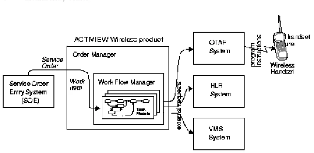
Order Entry System (SOE), converts inputs, and then automatically refers requests for provisioning to externalelement management systems. A given work item may require the processing of several such requests either in parallel or in series. Activiewanalyzes the responses to these requests and at each step determines the next appropriate task to be performed.
A major component of the Actiview system is the Order Manager
(OM). The OM module manages most of the data conversion required by the external components, executes the requests to external element man-agement systems and reads and updates internal databases. Another im-portantActiviewcomponent is the Work Flow Manager that tracks work items and directs the activities of the OM module. The Work Flow Man-ager is itself directed by instructions fromtask models, that are designed byActiviewSystems Engineers (SE).
Task models have nodes and edges. Each node holds a task, which can be an external request to an element management system, a database opera-tion, or an OM method. A typical fragment of a task model begins with an external request to an element management system, which is followed by a success task which updates the work item status or performs a database operation. It can also have one or more failure tasks which can retry some operations or defer the work item to a Manual Work List for human inter-vention. Task Models are created using a GUI based tool, called the Work Flow Editor.
TheActiviewWireless product supports automated provisioning of
ser-vice for wireless handsets. A consumer may purchase a handset at a cellular service store, a general merchandiser, or even from a vending machine. Be-fore service is initiated, the only available outgoing numbers are 911and
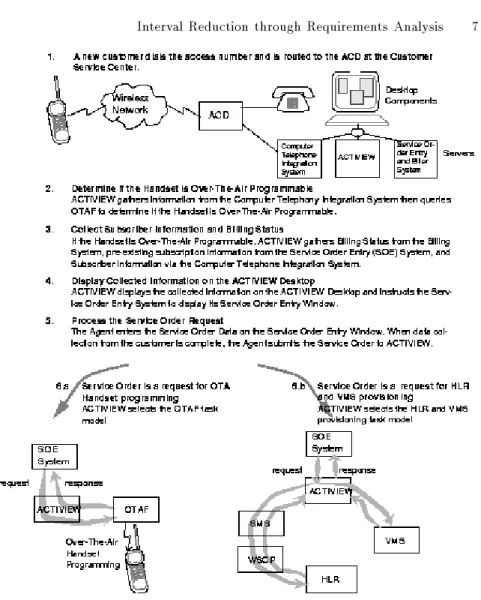
the telephone number for the Wireless provisioning system. A sticker on the handset instructs the buyer to dial this predened number to start telephone service on the handset. When the call is placed, it is connects to an Automatic Call Distribution (ACD) system that routes the call to an available agent. The agent will ask the caller about desired features, such as three-way calling, caller ID, and voice mail, and determines the geographical service areas for incoming and outgoing calls. The customer's choices are recorded by the agent on Service Order Entry (SOE) screens. When the service order is complete it is submitted toActiview.
The OM component creates a work item for each Service Order, it an-alyzes the data elds and selects the appropriate Task Model to perform the provisioning requested. Apart from the SOE system, three external el-ement managel-ement systems are used to carry out the instructions issued byActiview. Lucent's Over The Air Function (OTAF) System is used to
program the handset remotely, using radio frequency transmissions. The Home Location Record (HLR) system stores customer feature subscription information that is used by Mobile Switching Centers during the actual call handling. The Voice Messaging System (VMS) has a co-resident sub-scription database and provides for message storage for a customer when the wireless handset is turned o or busy.
Figure 1 depicts these systems and their relationship to theActiview
product. Depending on a given work item,Activiewmay request provi-sioning actions from all three external systems or from just one or two of these. For instance, if the work item is for new service and the customer requests a voice mail feature, OTAF will program the handset while the HLR record and the VMS records are being updated at the request of
Actiview. If the same customer calls back to terminate a three-way
call-ing feature requested earlier, only the HLR system will receive the request for modication fromActiview.Activiewknows which Task Model to
invoke to accomplish each specic request.
Figure 2 shows a simplied scenario of a typical use of theActiview
Wireless product.
The correct operation of the wireless service requires a coordinated provi-sioning of several disparate systems. The design of theActiviewsystem is intended to provide this coordination. A complicating factor in this process is thatActiviewis fundamentallya multi-systemproduct, combiningboth Lucent and non-Lucent systems. Knowledge of especially the non-Lucent components is limited to interface functionality only, which, in some cases, is only partially documented. The construction and formal verication of a model of this design, therefore, can also serve to reassure the designers
FIGURE 1.ActiviewWireless Product and External Components.
that the main assumptions made in the design process were justied.
5 The Spin Model
The full description of the requirements for the OM system are documented in approximately 250 pages of text (or roughly 15,000 lines), created over a period of ve months. The second author of this paper, was one of the authors for the original requirements for theActiviewproduct. The same author constructed the design prototype of the task models for the Ac-tiviewWireless product in an additional two weeks, which was then
re-viewed by the rst author. The two week period for the construction of the design prototype included a brief learning phase on the details of the
Spin model checker. When more targeted high level design capture tools
are used on a project, e.g., such as the Lucent UBETtool [4], the time
required to produce the intial verication models could be reduced further, and perhaps even avoided completely by taking advantage of the builtin model extraction capabilities of these tools.
The prototype contains abstract models of the SOE, OTAF, HLR, and VMS components, based on the Actiview interface specications. The
model was built in Promela, the specication language (or application modeling language, in the terminology of domain engineering), of Spin.
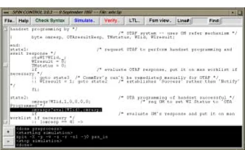
The nal model consists of 438 lines ofPromelatext. The GUI forSpin,
showing part of this prototype, is illustrated in Figure 3.
After the prototype was constructed, the authors spent one afternoon to debug the model; usingSpinfor random and interactive simulations. Some unnecessary assumptions were removed, the model was rened, and logical
FIGURE 2.ActiviewProvisioning Scenario.
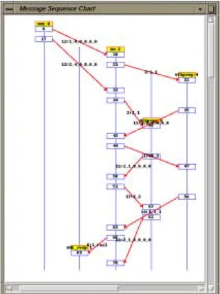
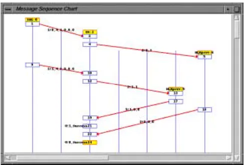
correctness requirements were added. Each simulation run was displayed by Spin in graphical form as an annotated message sequence chart, as
illustrated in Figure 4.
With the help of simulations, unwarranted abstractions that were made to construct the prototype itself from the written requirements were iden-tied and removed. Once the simulation of the prototype conformed, as far as could be observed, to the intended behavior of the system, as far as doc-umented, the actual model checking process could begin. In this reviewing process the initial prototype of 1,100 lines ofPromela was reduced to a model of 438 lines.
FIGURE 3. Main Control Panel for theSpinModel Checker.
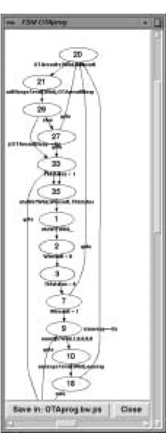
The model describes the behavior of 17 logical processes within the sys-tem, communicating through 20 buered message channels, each with a capacity to store up to four messages (each message with multiple data elds). Each logical process has between 20 and 50 distinct control states, and has access to between 5 and 10 local variables to store temporary results. The control states can be made visible in automaton form, as il-lustrated in Figure 5, but for most applications this detail is not needed to perform the verications.
6 Requirements Analysis by Model Checking
To perform verication, theSpinsystem converts the prototype specica-tion from an automata model into an optimized program in standard C. This program is then compiled and executed to perform the verication. The result consists either of a terse statement that the correctness proper-ties are valid for the system as specied, or (more typically) the generation of one or more detailed counter-examples that demonstrate that there are logical inconsistencies in the model. The counter-examples, or error-trails, can be inspected with the help ofSpin's simulation capability, either step
by step, or by using the trail for a guided simulation run, supported by message sequence charts, data displays, etc.
An exhaustive verication run for the system as specied analyzes up to 7 million distinct system congurations. The longest execution scenario
FIGURE 4.SpinDisplay of Simulation Run.
encountered in this verication is 6,793 steps. This verication run is com-pleted in approximately30 minutes of CPU time on an average workstation. It is not necessary, however, to let the verication run proceed until completion. Spin's on-the-y model checking algorithm by default stops
the verication attempt as soon as it can prove that at least one of the correctness properties can be violated. In this application, this occurs after just a few seconds of runtime, and the inspection of only a few hundred carefully chosen system congurations.
The property we set out to prove in this verication attempt was:
\The status of the wireless handset on any particular feature requested
by the customer always corresponds to the last provisioning request that was submitted by the customer for that feature."
The critical term here issubmitted. As the model checker demonstrates within seconds, the order of submission of provisioning requests does not
FIGURE 5. Automaton Structure for OTAprog Process Computed bySpin.
necessarily correspond to their order of processing. The counter-example is displayed by the model checker as the message-ow diagram shown in Figure 6.
Consider a customer who requests three-way calling, is informed of the cost and other details by the operator, during the entry phase of the pro-visioning request, and decides after a short time that the cost is too high and submits a new request to cancel the feature. There is no guarantee in the system as designed that the provisioning for the second request is not completed before the rst request. The result of the rst processed request would then be void, since it involves the canceling of a feature that was not available to the customer. The result of the request processed second would be a successful installation of the feature, despite the customer's explicit cancellation. In Actiview it is assumed that the status of the handset always corresponds to the last provisioning request. It can be dicult to secure that the design that is selected can indeed never violate this as-sumption. The designers can reason about the design to establish that for
all reasonable cases that can be imagined, this assumption is valid. With and automated verier, though, the designer can prove with certainty, that a design guarantees the validity of the assumption forall possible execu-tions, both the imaginable and the unimaginable ones.
FIGURE 6. Scenario Generated bySpinShowing Violation of Requirement
The discovery that the model fails to reliably provide a stated property can initiate a discussion with the customer about the relative importance of the fault. In this case, a minor redesign of the Order Manager suces to secure the required coordination between related workitems, an guarantees reliable service under all circumstances.
7 Conclusions
The verication of design requirements in the early phases of, especially the larger, software design projects requires a relatively small investment of skill and eort. There is a potentially large return on this investment in reduced interval time and project cost, by avoiding unpleasant discoveries of design faults late in the design cycle. Early fault detection tools of the type we have discussed have not yet been exploited fully in industrial design projects. The skills that are required to use these tools well are limited to basic skills in model construction, and abstraction, i.e., skills that may also
prove valuable in other aspects of systems design.
Model checking tools have been studied for almost two decades. The
Spin system, for instance, is based on a development at Bell Labs that
dates back to 1980. The increase in the speed of computers and in the amount of memory they can access, by several orders of magnitude each, and the graphical capabilities that most desktop computers today support, have all contributed to turning our tentative rst eorts towards developing software verication tools into the availability of powerful new desktop tools that can be used with almost push-button ease by engineers in the development of robust software products.
Acknowledgements
The following are gratefully acknowledged for their technical input on
Actiview: Myrna Papier, Elliot Pludwinski and Shel Rockowitz.
8 References
[1] A.R. Flora-Holmquist, E. Morton, J.D. O'Grady, and M.G. Staskauskas, 'The Virtual Finite-StateMachine Design and Implemen-tation Paradigm',Bell Labs Technical Journal, Vol. 2, No. 1, 1997, pp 96-113.
[2] G.J. Holzmann, 'Early Fault Detection Tools,'Software Concepts and Tools, Vol. 17, No. 2, 1996, pp. 63-69. Also in: Lecture Notes in Com-puter Science, Vol. 1055, pp. 1-13.
[3] G.J. Holzmann, 'The Model Checker Spin,' IEEE Transactions on Software Engineering, Vol. 23, No. 5, May 1997, pp. 279-295.
[4] G.J. Holzmann, D.A. Peled, and M.H. Redberg, 'Design Tools for Re-quirements Engineering,' Bell Labs Technical Journal, Vol. 2, No. 1, 1997, pp. 86-95.
[5] R.P. Kurshan, Computer-Aided Verication, Princeton University Press, 1994.
[6] K.L. McMillan,Symbolic Model Checking, Kluwer, 1992.
[7] A. Pnueli, 'The temporal logic of programs,'Proc. 18th IEEE Sympo-sium on Foundations of Computer Science, 1977, pp. 46-77.
[8] SpinWebpage, containing tool sources, test cases, and documentation.
Acronyms Used
ACD - Automatic Call Distribution AML - Application Modeling Language GUI - Graphical User Interface HLR - Home Location Record LTL - Linear Temporal Logic MSC - Mobile Switching Center OM - Order Manager
OTAF - Over The Air Function
Promela - Process Meta Language, the AML ofSpin SOE - Service Order Entry System
SE - System Engineers SOE - Service Order Entry
Spin - The LTL Model Checker used TM - Task Model
VMS - Voice Messaging System WFE - Work Flow Editor WFM - Work Flow Manager