The Geomorphic View of Networking:
A Network Model and Its Uses
Pamela Zave
AT&T Laboratories—Research Florham Park, New Jersey, USA
[email protected]
Jennifer Rexford
Princeton University Princeton, New Jersey, USA[email protected]
ABSTRACT
The Internet is evolving away from its original architecture and toward the use of multiple, customized protocol stacks. A pluralistic architecture is best explained by the “geomor-phic view” of networks, in which each layer is a microcosm of networking, and layers can be instantiated at many different levels, scopes, and purposes. Exploiting the commonalities identified by the geomorphic view, an abstract layer model can lead to architectural insights that help extend commu-nication services, derive design principles, and generate net-work software.
Categories and Subject Descriptors
C.2.2 [Network Protocols]: Protocol Architecture
General Terms
Design, Performance, Security, Verification
Keywords
Internet, overlay, mobility
1.
INTRODUCTION
The “classic” Internet architecture is usually depicted with five layers: physical, link, network, transport, and applica-tion. It is now widely agreed that this architecture fails to meet many of society’s present and future requirements [3, 6, 7]. The Internet is evolving as numerous stakeholders attempt to meet their goals for dependability, security, mo-bility, scalamo-bility, quality of service, and improved resource management. The result is a trend toward multiple, cus-tomized protocol stacks.
Multiple, customized protocol stacks can be envisioned in a principled way as a future pluralistic Internet architecture [1, 5, 13]. The present incarnation of the trend is more pragmatic than principled, but nevertheless effective. For example, Figure 1 shows the headers of a typical packet in the AT&T backbone network. Counting one layer per
Permission to make digital or hard copies of all or part of this work for personal or classroom use is granted without fee provided that copies are not made or distributed for profit or commercial advantage and that copies bear this notice and the full citation on the first page. To copy otherwise, to republish, to post on servers or to redistribute to lists, requires prior specific permission and/or a fee.
MW4NG’12 December 3-7, 2012, Montreal, Canada Copyright 2012 ACM 978-1-4503-1607-1/12/12 ...$10.00.
Application
HTTP
TCP
IP
IPsec
IP
GTP
UDP
IP
MPLS
MPLS
Ethernet
Figure 1: Headers of a typical packet in the AT&T backbone network.
header, this packet is handled by an architecture with twelve layers above the physical, instead of the classic four.
In this customized architecture, every layer above the UDP layer and below the application is middleware. GTP is a cell-phone protocol providing mobility, quality-of-service, and billing. IPsec provides security. HTTP is serving as a trans-port protocol, not because it is suitable for the application or even designed as a transport protocol, but because it is almost the only way to traverse NAT boxes and firewalls [12]. The presence of two MPLS layers, three IP layers, and two transport protocols from the IP suite is an indication of ad hoccode re-use, as protocols are instantiated at different positions in the stack to serve different purposes.
The good news to be found in Figure 1 is that middleware can be used to meet a wide variety of requirements, even for those stakeholders who cannot influence the lower layers of the architecture.
The bad news to be found in the figure is more exten-sive. It illustrates major problems and unmet needs in the following three areas.
Communication services: HTTP is a transaction-oriented client-to-server protocol. Although it supports Web ser-vices fairly well, there is a wide variety of potential In-ternet applications for which it is poorly suited. These include real-time, connection-oriented, peer-to-peer, server-to-client, and multi-party applications. When implemented on top of HTTP, these applications are difficult to develop,
A B
C D E
Figure 2: Members and links of a layer.
difficult to deploy and maintain, and very inefficient [15]. We need to provide a broader range of communication ser-vices so that all applications can be developed easily and efficiently, while security policies appropriate to each appli-cation are reliably enforced.
Design principles: With so many layers, this customized architecture is very unlikely to be the most efficient way to satisfy the stakeholders’ requirements. In fact, there is no way of predicting what its performance properties are, as an estimated 15 load-balancing algorithms apply to each packet, and each of the algorithms has been designed and analyzed mostly in isolation [14]. We need principles to help us design customized architectures that meet a variety of functional and nonfunctional requirements in an efficient, modular, and predictable way.
Software development: If the Internet evolves so that each application runs on its own customized Internet architec-ture, then a large amount of new network software will be required. We need to develop this software through code re-use and code generation, because conventional program-ming will be too slow, too expensive, and too prone to er-rors. Figure 1 shows code re-use, but does not meet other requirements such as efficiency and predictability.
This paper outlines a research agenda aimed at solving these problems. It is based on a “geomorphic view” of net-works, in which each layer is a microcosm of networking—it has all of the basic ingredients of networking in some form. Layers are the architectural modules. In a network architec-ture there are many layer instances; they appear at differ-ent levels of the “uses” hierarchy, with differdiffer-ent scopes, with different versions of the basic ingredients, and for different purposes. This view is described in more detail in Section 2. The beauty of the geomorphic view is that any lesson we learn about layers in general can be used many times over. Section 3 explains how it might be possible to develop an abstract, formal model of a layer that would be helpful in solving the problems introduced above. We discuss both the abstractions and our progress on building such a model.
Finally, Section 4 proposes some ways in which the layer model could be exploited to solve the problems above. First, it could delineate design spaces and elucidate how decisions in one space depend on decisions in other spaces, leading to principles of network design. Second, it could broaden the set of mechanisms available to network designers, leading to a richer set of communication services without sacrificing other goals such as dependability, security, performance, and scalability. Third, it could serve as a framework in which a custom layer can be generated by selecting and integrating library components.
2.
THE GEOMORPHIC VIEW
OF NETWORKS
registration processes on one machine A E a b d eFigure 3: Implementation of a link in an overlay by a session in an underlay.
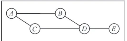
In the geomorphic view of networks, the architectural module is alayer. A layer hasmembers, each of which has a unique, persistentname. For example, Figure 2 is a snapshot of a layer with five members, each having a capital letter as a name. In general a member is a process,i.e.,an indepen-dent, asynchronous locus of state and control. The actual behavior of a member may be no more complex, however, than a sequence of procedure calls.
The members of a layer communicate with each other throughlinks, shown by lines in Figure 2. A link is a com-munication channel. In general, a layer does not have a link between each pair of members.
One of the two primary functions of a layer is to enable members to send messages to each other. To do this, a layer needsroutesindicating how one member can reach another through links and intermediate members. For example, (A, B, D, E) is a route fromAtoE. It also needs aforwarding protocolthat runs in all members. The forwarding protocol enables members to send and receive messages. In addition, when a member receives a message on an incoming link that is not destined for itself, its forwarding protocol uses the route information to decide on which outgoing link it will forward the message.
Achannelis an instance of a communication service. As mentioned above, a link is a channel. If a layer does not implement its links internally, then its links are implemented by other layers that this layer uses, placing the other layers lower in theuses hierarchy.
If an underlay (lower layer) is implementing a link for an overlay (higher layer), then the state of the channel must be stored as data in the underlay. In the underlay, the channel is known as asession. (There must be two names for chan-nels, because a typical layer has both links and sessions.)
The second primary function of a layer is to implement enriched communication services on top of its bare message transmission. Typical enrichments for point-to-point ser-vices include FIFO delivery and quality-of-service guaran-tees. This function is carried out by a session protocol. A layer can implement sessions on behalf of its own members, as well as or instead of as a service to overlays.
For a link in an overlay to be implemented by a session in an underlay, both endpointmachinesmust have members in both layers, as shown in Figure 3. Amachineis delimited by an operating system that provides fast, reliable communica-tion between processes on the machine. This fast, reliable
primary function state component maintenance algorithm member algorithm location algorithm attachment algorithm link algorithm routing algorithm members locations sessions attachments links routes session protocol forwarding protocol
Figure 4: Major components of a layer. Arrows
show which protocol or algorithm writes a state component.
operating-system communication is the foundation on which networked communication is built.1
Aregistration is a record that relates an overlay member to an underlay member on the same machine. Registrations must be stored as data in both layers. In the overlay they are calledattachments, because they indicate how a member is attached to the network through a lower layer. In the underlay they are calledlocations, because they indicate that a member is the location of a process in a higher layer.
The session protocol creates and maintainssessionsdata in its layer, and useslocations data. For example, in Fig-ure 3,A sent a request toafor a session withE. To create this session, a learned from its layer’s locations that E is currently located ate. Messages sent fromAtoE through the link in the overlay travel througha, b, d,ande; the first and last steps uses operating-system communication, while the middle three steps use networked communication.
The six major components of the state of a layer are listed in Figure 4. All can be dynamic. We have seen that the session protocol creates and maintains sessions; the other five are created and maintained by their own maintenance algorithms.
This view of networking was inspired by the work of Day [4], although we have made many changes and additions in both content and presentation. It may seem familiar and ob-vious because both the classic Internet architecture [2] and the OSI reference model [9] also describe network architec-ture as a hierarchy of layers, but in fact there are several radical differences, which the name “geomorphic” has been chosen to emphasize.
In the Internet and OSI architectures, each layer has a spe-cialized function that is viewed as different from the func-tion of the other layers. In both architectures, there is a fixed number of global layers. For example, in the Inter-net architecture the Inter-network layer is defined by IP, while the transport layer is defined primarily by TCP and UDP. If the earth’s crust resembled these architectures, it would consist of exactly five or seven smooth and unbroken layers, each surrounding the earth like a shell. In the geomorphic view the arrangement of layers is more varied and complex, as it actually is in the earth’s crust.
In the geomorphic view, each layer is viewed as the same in containing all the basic functions of networking, and there can be as many layers as needed. Consequently, the network (IP) and transport (TCP/UDP) layers of the Internet archi-tecture fit into one “Internet core” layer of the geomorphic view, where IP is the forwarding protocol and TCP and 1A virtual machine can be regarded as amachine, in which case communication through the hypervisor and soft switch of the physical machine is regarded as networked communi-cation.
LAN 1 LAN 2 LAN 3
1 2 2 3
gateway gateway
Application 1
Application 2
Internet core
Figure 5: Geomorphic view of the classic Internet
architecture. Internet links are labeled with the
LAN that implements them.
UDP are variants of the session protocol offering variants of Internet communication service.
Because layers instantiated at different levels have differ-ent purposes, their functions take differdiffer-ent forms. For one example, we are most familiar with routing algorithms in the Internet core, where their purpose is reachability. A higher-level middleware layer might offer security as part of its communication services. Implementing security might en-tail routing all messages to a particular destination through a particular filtering server, so that, in this layer, part of the purpose of routing is security. An application layer might have a link or potential link between any two members, im-plemented by communication services below, so that in this layer the routing algorithm is vestigial.
For another example of a basic function with different forms in different layers, low-level layers such as Ethernet LANs provide broadcast as a communication service. The services provided by the Internet core are point-to-point, while an application layer might implement its own form of broadcast.
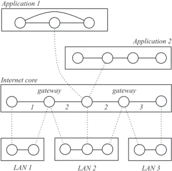
Thescopeof a layer is its set of potential members. In the Internet and OSI architectures there is exactly one layer at each level of the hierarchy. In the geomorphic view, as shown in Figure 5, a layer can have a small scope, and there can be many layers at the same level of the hierarchy. Figure 5 shows the geomorphic view of the classic Internet architec-ture, with many LAN layers at the bottom level. In each LAN layer, the data structures, algorithms, and protocols are precisely those of the particular LAN technology being used. This is in sharp contrast to the idea of a generic, global “link layer,” which cannot be made precise because it is a generalization of a large number of different technolo-gies.
Figure 5 also shows that each application is a layer with its own members, name space, and communication services.
These layers overlap geographically, while sharing the re-sources of the Internet core. The overlapping and abutting shapes in Figure 5 are common to both geological diagrams and networking.
It is self-evident that fixed layer structures cannot explain today’s customized architectures, as exemplified by Figure 1. The geomorphic view is intended not only to describe them,2 but also to generate a design space including many others not yet explored.
3.
TOWARD AN ABSTRACT LAYER MODEL
Our goal is to develop an abstract formal model of a layer, so that we can exploit it to solve the problems presented in Section 1. Because the diversity of network technologies and the overall complexity of networking make this goal appear quixotic, we first explain some of the factors that make this goal feasible, before summarizing our progress.
3.1
What makes a useful layer abstraction
seem feasible?
As noted above, each layer instance corresponds to some-thing real and specific, such as a particular LAN, as opposed to a generalization. This means that we can compare a real layer instance to an abstract formal model, and decide with-out ambiguity whether the layer instance is a special case of the formal model.
Although the geomorphic view is not intended to limit network functions in any way, it is intended to be somewhat prescriptive in how they are described. For one example, a layer has one name space, in which a member has one name. It follows that if there appears to be a process with an “identifier” and a “locator,” it must actually be two processes on the same machine, each in a different layer, with one being registered to the other. For another example, there is no concept of tunneling within a layer. Wherever “tunneling” is used, the “tunnel” is a link in one layer, and it “tunnels through” the links of a lower layer. For this reason, the two MPLS layers in Figure 1 must also be two distinct layers in the geomorphic view.
Prescriptive description brings many benefits. Most rel-evant to this subsection, each layer is a simpler structure, because it need not include multiple name spaces, tunnels, and other unnecessary complexities. Another benefit is that it forces designers to make explicit decisions that are usually left unexplained or even undefined, such as the purposeful relationship between routing in an overlay (whose links are “tunnels”) and routing in the underlay (whose routing imple-ments the tunnels). Finally, prescriptive description helps ensure that each architecture has only one correct descrip-tion, rather than many synonymous ones. This should prove beneficial in comparing architectures and generating design spaces.
In our current layer model most data structures ( mem-bers, attachments, locations, links,androutes) are regarded as centralized, or, more precisely, their distribution over the states of layer members is not specified. In the same way, the functional components that maintain them (member, attach-ment, location, link,androuting algorithms) are specified as 2In the geomorphic view Figure 1 would probably corre-spond to 7 layers, from bottom to top: Ethernet, MPLS, MPLS, IP+UDP+GTP, IP+IPsec, IP+TCP+HTTP, Ap-plication.
link
layer benefiting
from mobility
layer
imple-menting
mobility
lower
layers
L1
a1’
a2’
L2
b1’
b2’
L3
A
B
a
b1
b2
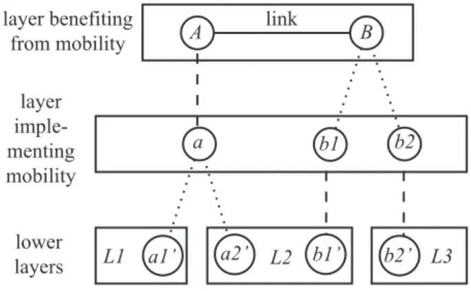
Figure 6: A session with attachment mobility
serv-ing endpoint A and location mobility serving
end-point B. Dynamic registrations are shown as dotted
lines.
(centralized) algorithms rather than (distributed) protocols. This abstraction is extremely important because most of the difficult decisions made in designing a network layer are about or related to how the state is distributed, and how protocols maintain adequate consistency across the layer. Choices range from initializing state structures that cannot change thoughout the life of a layer, through using a cen-tralized database with lookup and update transactions, to highly redundant, distributed state and complex consistency protocols. These choices, in concert with choices about the shape of the member/link graph, the structure of names, and other constraints, are the major influences on scale, perfor-mance, and dependability. We cannot defer these choices forever, but the abstraction enables us to defer them until they are relevant.
3.2
Progress on the model
We have a formal model of a point-to-point session pro-tocol written in Promela, and have verified many desirable properties with the model-checker Spin [8]. We have a for-mal model of members, attachments, locations, links, ses-sions, routes, and the forwarding protocol written in Alloy, and have verified static consistency properties with the Al-loy Analyzer [10]. Relatively little is included about the algorithms that maintain these data structures.
Most of our efforts have been expended on investigating and modeling the layer mechanisms needed formobility. In networking, this term refers to both a problem and its solu-tions. As a problem, it means that a layer member is chang-ing its attachment to lower layers of the network, in partic-ular while using communication services. As a solution, it means maintaining the member’s communication channels, despite the movement.
Using the geomorphic view, we have discovered that there are two completely distinct mechanisms for implementing mobility. Figure 6 shows a layer with two mobile members A and B. Both are benefiting from mobility, in the sense that their link will be preserved as they move. The mobility of each endpoint is provided by a different mechanism.
On the left, as the machine ofAmoves physically, it goes out of range of LAN L1 and enters the range of LANL2.
Consequently, its attachment in the lowest level changes froma1’toa2’. In the middle layer, which is implementing mobility, this means that links toaimplemented byL1are replaced by links toa implemented byL2. The hard work in this layer is performed by its routing algorithm, which must re-route to maintain the reachability ofathrough new links. The parts of the layer state affected by this mecha-nism, calledattachment mobility, are its attachments, links, and routes.
On the right, as the machine of B moves physically, it goes out of range of LANL2and enters the range of LAN L3. Consequently, its attachment in the lowest level changes fromb1’to b2’. Although this is exactly the same at this level asA’s mobility, it is handled by the implementing mid-dle layer in a completely different manner.
In the middle layer, the location ofBchanges from mem-ber b1 to member b2. The most common reason for this to occur is that the implementing layer has a large, hier-archical, topology-dependent name space (as the Internet does). As the machine ofBmoves fromL2toL3, it cannot keep the same name in the middle layer, because topolog-ical constraints would be violated. Instead, its memberb1 in the middle layer dies and is reborn as memberb2. The hard work in this layer is performed by its session protocol and location algorithm. The location algorithm must up-date B’s location, while the session protocol must update distributed session state so thatasends messages tob2 in-stead of b1. The parts of the layer state affected by this mechanism, calledlocation mobility, are its members, loca-tions, and sessions.
On first hearing this explanation, most people insist that the difference between attachment and location mobility must be illusory, merely a difference of viewpoint. The geomor-phic view shows, precisely and unambiguously, that the dif-ference is real: the two mechanisms exercise disjoint pro-tocols and algorithms in a layer, and alter disjoint data structures. In [16] we elaborate the detailed design decisions needed within each of the two major mechanisms, and use these structures to categorize and explain all the well-known implementations of mobility.
Our next step toward an abstract layer model will be to investigate and model security mechanisms. Although some aspects of security belong strictly in the operating system or application, others can be provided as part of network ser-vices (e.g.,encryption and authentication) or supported by network services (e.g.,guaranteed routing through security servers). The latter aspects can be investigated and modeled in the same spirit as mobility.
Overall, our abstract layer model is at a very preliminary stage—it is rudimentary or incomplete in most places. Thus it is still too early to tell whether most of its potential ben-efits can be realized.
4.
USING THE MODEL
TO SOLVE PROBLEMS
In this section, we suggest how the previous ideas might contribute to solving the problems introduced in Section 1.
4.1
Communication services
As previously mentioned, restrictive policies embedded in most firewalls and NAT boxes make it very difficult to imple-ment many applications, particularly those requiring
real-time, peer-to-peer, or server-to-client communication ser-vices. Those restrictive policies exist because of the Inter-net’s security crisis, but they are a blunt instrument.
With a carefully structured and articulated architecture, it should be possible to build in higher-level security policies that are sound and appropriate to their applications. This work could provide the basis of an argument for bypassing the blunt security policies enforced at lower levels of the hierarchy.
The geomorphic view also promotes clean, well-specified interfaces between layers. This improved understanding of network architecture might encourage middleware designers to offer a richer set of communication services to applica-tion developers, and might encourage applicaapplica-tion develop-ers to use well-engineered middleware services rather than program their own versions.
Richer communication services might include anycast, con-ference, and publish/subscribe channels. They might in-clude “multihomed” channels that can take advantage of the bandwidth of both cellular and WiFi media simultaneously. Or they might include services based on routing through application-specific middleboxes.
4.2
Design principles
Our work toward developing design principles breaks into two parts. The first is concerned with solving individual design problems. The second is concerned with composing individual solutions into an architecture that solves many problems simultaneously. We illustrate both parts with a mobility example.
Imagine that we are designing a mobility service for lap-tops. Laptops are often used on buses, because each bus has its own LAN for the benefit of its riders. Of course, the bus is mobile also. We might see this as breaking into two mobility problems, one for buses and one for laptops. It is important for scalability that solutions to the two problems be independent. In other words, we cannot accept solutions that require an update for every rider when a bus moves, nor can we accept solutions that require an update for the bus when a rider with a laptop gets on or off.
Assuming that there is already a tentative layer architec-ture, a solution to either of the mobility problems might be assigned to any layer, and it might be a special case of attachment mobility or a special case of location mobility. If a layer L is going to implement location mobility for a layerL+above it, then the name spaces ofLandL+ can-not be in one-to-one correspondence (see Figure 6), andL must have an efficient location algorithm that makes the lo-cations of mobile members of L+available throughout the layer. If a layer L is going to implement attachment mo-bility, then there are quite a few choices concerning howL will optimize the update, storage, and path-stretching costs of dynamic routing (see [11] for an overview of these costs). These choices constitute the design space of a mobility prob-lem. By studying these choices further, we hope to gain more insight into the qualitative and quantitative constraints and trade-offs relevant to solving individual design problems.
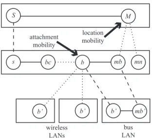
Figure 7 shows a new solution to the joint problem, gen-erated from the design space of mobility, that has the in-dependence and scalability advantages explained above. In the figure, the top layer contains a middleware process M on a mobile laptop, with an ongoing link to a middleware processS. In the layer below,b is the Internet interface of
wireless LANs S M bus LAN s bc b mb mn b’ mb’ b’ b’ location mobility attachment mobility
Figure 7: An implementation of mobile laptops on a bus.
a bus LAN. When the laptop is on the bus,Mis registered at Internet interfacemb, andbis acting as a router formb. Note thatbandmbbelong to the same block of Internet ad-dresses, so when the laptop is taken off the bus and attached somewhere else, it will register at a different processmn.
The big arrows indicate the processes benefiting from mo-bility and the type of momo-bility, but not where it is imple-mented. In fact, both mobility problems are solved in the same layer. The middle layer implements location mobility forM. This implementation must do something special to update sessions and locations when the laptop moves on or off the bus, but does nothing when the laptop is on the bus and the bus is moving. The middle layer also implements attachment mobility for b. This implementation must do something special to restore links and routing when the bus moves from the range of one roadside wireless LAN to an-other, but does nothing when riders get on or off the bus.
In a network architecture, different mobility problems might be solved in different, adjacent layers. We have used the layer model presented in Section 3 to argue that mobil-ity solutions in different layers are independent and non-interfering. In other words, layer composition (in which an overlay uses the services of an underlay) continues to work smoothly.
In Figure 7, different mobility problems are solved by dif-ferent mobility mechanisms in the same layer—another kind of composition. We are currently completing a proof that location and attachment mobility mechanisms in the same layer are independent and non-interfering, so that they can be composed safely.
One of the goals of composition, both inter- and intra-layer, is more efficient architectures. For example, it has been noted that Figure 1 appears to correspond to 7 lay-ers in the geomorphic view. It is almost certainly possible to implement the same functions in fewer layers, if that is desirable for compressing headers or minimizing header pro-cessing. For example, the purpose of IP + UDP + GTP appears to be independent of the purpose of IP + IPsec. If the mechanisms implementing these purposes can be shown to be equally independent and therefore compositional, then
both can be combined in a single layer, possibly along with other functions as well.
4.3
Software development
As indicated in Figure 4, the layer model is intended to decompose the software structure of a layer into com-ponents with well-understood interfaces and dependencies. The structure in the figure is very coarse, but further work should make it possible to refine it.
Hopefully the refined structure can serve as a framework where specific implementations of mechanisms such as loca-tion and attachment mobility plug in. If so, the software framework brings us closer to being able to generate a cus-tom layer by selecting and integrating library components.
5.
REFERENCES
[1] K. Birman. The league of SuperNets.IEEE Internet Computing, 7(5):93–96, September 2003.
[2] D. D. Clark. The design philosophy of the DARPA Internet protocols. InProceedings of SIGCOMM. ACM, August 1988.
[3] D. D. Clark, J. Wroclawski, K. R. Sollins, and R. Braden. Tussle in cyberspace: Defining tomorrow’s Internet.IEEE/ACM Transactions on Networking, 13(3):462–475, June 2005.
[4] J. Day.Patterns in Network Architecture: A Return to Fundamentals. Prentice Hall, 2008.
[5] N. Feamster, L. Gao, and J. Rexford. How to lease the Internet in your spare time.Computer
Communications Review, 37(1):61–64, January 2007. [6] A. Feldmann. Internet clean-slate design: What and
why? Computer Communications Review, 37(3):59–64, July 2007.
[7] M. Handley. Why the Internet only just works.BT Technology Journal, 24(3):119–129, July 2006.
[8] G. J. Holzmann.The Spin Model Checker: Primer and Reference Manual. Addison-Wesley, 2004.
[9] ITU. Information Technology—Open Systems Interconnection—Basic Reference Model: The basic model. ITU-T Recommendation X.200, 1994. [10] D. Jackson.Software Abstractions: Logic, Language,
and Analysis. MIT Press, 2006, 2012. [11] J. Mysore and V. Bharghavan. A new
multicasting-based architecture for Internet host mobility. InProceedings of the 3rd Annual ACM/IEEE International conference on Mobile Computing and Networking. ACM, 1997. [12] L. Popa, A. Ghodsi, and I. Stoica. HTTP as the
narrow waist of the future Internet. InProceedings of the 9th Workshop on Hot Topics in Networks, 2010. [13] T. Roscoe. The end of Internet architecture. In
Proceedings of the 5th Workshop on Hot Topics in Networks, 2006.
[14] O. Spatscheck. Cloud computing and my worries about the network that enables it.
http://clouds10.mytestbed.net/presentation/ oliver_clouds10v2.pdf, 2010.
[15] P. Zave. Internet evolution and the role of software engineering. InThe Future of Software Engineering, pages 152–172. Springer, 2011.
[16] P. Zave and J. Rexford. The geomorphic view of mobility. In submission, 2012.