Finite Element Simulation and Experimental Investigation of Friction
Stir Welding of AA2219 and AA2014
K V L Prasanna#1, P.Satish Reddy#2, N.Guru Murthy#3 Scholar of Master of Technology, Assoc. Professor, Asst Professor Dept of Mechanical Engineering, Prasiddha College of Engg & Tech, Anathavaram
[email protected], [email protected], [email protected]
Abstract:
In FSW, a rotating cylindrical pin tool is forced to plunge in to the plates to be welded and moved along their contact line. The tool penetrates into the work pieces. During this operation, frictional heat that is generated by contact friction between the tool and workpiece. The plasticized material is stirred
by the tool and forced to “flow “ to the side and the
back of the tool as the tool advantages as the temperature cools down, a solid continuous joint between the two plates is than formed.
In this project work, DEFORM -3D is used to perform the finite element analysis and experimental investigation on the FSW in order to predict residual stresses, temperatures, normal stresses and distortion of the welded structures, that are induced during FSW of the given airframe structures made up of AA 2219 and AA 2014. A new technique of filling friction stir welding (FFSW) relying on a semi consumable joining tool has been developed to repair the keyhole left at the end of friction stir welding (FSW) seam. The FFSW process is able to repair the keyhole with both metallurgical and mechanical bonding characteristics and the FSW seam can be achieved without keyhole and other defects.
Keywords: Finite Element Simulation,
DEFORM-3D, Friction Stir Welding, AA2219 and AA2014
I.INTRODUCTION
Friction Stir Welding is a solid state joining
technique, invented at “The Welding Institute”,
United Kingdom, in 1991. The Friction Stir Welding is an effective tool used for Joining Difficult-to-weld metals such as aluminium alloys, magnesium alloys, titanium alloys etc, joining plates with different materials and joining plates with different thickness.
In the Friction Stir Welding process, a non-consumable rotating tool is inserted into the abutting edges of the work-piece. The tool is then transverse along the line of joint. The tool is specially designed with a pin and shoulder. The tool serves two primary functions: firstly heating of work piece, secondly, movement of material to produce the joint.
FRICTION STIR WELDING MECHANISM
II.MATERIAL DESCRIPTION INPUT PARAMETERS
The objective of this thesis is to predict the Temperature distributions, stresses on an Aluminium Alloys – AA2014 and AA 2219 work piece during the friction stir welding process using a specified threaded tool by numerical simulation. The different welding parameters used in this project are
Rotational speed of 760, 1130 & 1340 rpm at welding speed 11 & 25 mm/min for AA 2219.
Property of Alloys AA2219 AA 2014
Density (g/cc) 2.84 2.8
Brinell Hardness (BHN) 115 550
Tensile strength (MPa) 290 400
Ultimate Strength (MPa) 414 480
Poisson’s Ratio 0.33 0.33
Modulus of Elasticity
(GPa) 73.1 73.1
Thermal
Conductivity(W/mK) 170 121
Melting Point (0C) 510 535
Element % AA2219 AA2014
Iron, Fe 0.3 0-0.5
Copper Cu 6.3 3.8-4.9
Manganese, Mn 0.03 0.30-0.9
Zirconium, Zr 0.18 0-0.25
Chromium, Cr 0.1 0.1
Titanium, Ti 0.06 0-0.15
Silicon Si 0.5
Nickel Ni 0-0.1
Magnesium Mg 1.2-1.8
III. WORK PIECE GEOMETRY
In this thesis, 6mm thick aluminium 2219 alloy and aluminium 2014 alloy plates are butt welded using Friction Stir welding using the Finite element simulation software DEFORM-3D.
Length of each plate = 150 mm
Width of each plate = 120 mm
Thickness of each plate = 6 mm
For the numerical analysis, as single block approach is used for Friction Stir Welding, the modelling of work piece is done as a single work piece whose configuration is shown in the fig. below
IV. FSW TOOL
The selection of tool material and tool geometry plays a vital role in the Friction Stir Welding. In this thesis, for Friction Stir Welding of aluminium 2014, 2219 plates, H-13 Steel is used as the tool material. H-13 Steel is chromium, molybdenum, vanadium hot work tool steel which is characterized by high hardenability and excellent toughness. The molybdenum and vanadium act as strengthening agents. The chromium content assists H-13 to resist softening when used at high temperatures. H-13 offers an excellent combination of shock and abrasion resistance, and possesses good red hardness. It is capable of withstanding rapid cooling and resists premature heat checking. H-13 have good machinability, good weldability, good ductility, and can be formed by conventional means.
Property of H-13 Value
Density (g/cc) 7.78
Brinell Hardness (BHN) 180
Ultimate Tensile strength (MPa) 1420 - 1810
Modulus of Elasticity (GPa) 210
Thermal Conductivity (W/((mm K)
) 0.0243
Specific Heat (J / kg K) 460
Composition of H-13 Steel
Element %
Iron, Fe 90.6
Manganese, Mn 0.4
Carbon, C 0.39
Chromium, Cr 5.2
Silicon Si 1
Molybdenum, Mo 1.4
FSW tool Configuration and its geometry specifications
Tool Parameter Value
Diameter of the shoulder 25 mm
Height of the shoulder 50mm
Upper diameter of the pin 6 mm
Lower diameter of the pin 3 mm
Height of the pin 5.7 mm
Pitch of the thread 1.25 mm
Tilt angle 2 deg
Thread orientation Counter clockwise
V SOLUTION METHODOLOGY
The continuous model proposed assumes the sheets to be welded as a single block. This FE model takes into account the actual interaction between the tool and the work piece allow to get a description of the process closer to reality. In particular asymmetric distributions of temperature, strain and strain rate are calculated by such models. CATIA - V5 is one of the modeling software which is used in this thesis to model the tool and work piece.
Fig: 5.1 Tool design in CATIA - V5
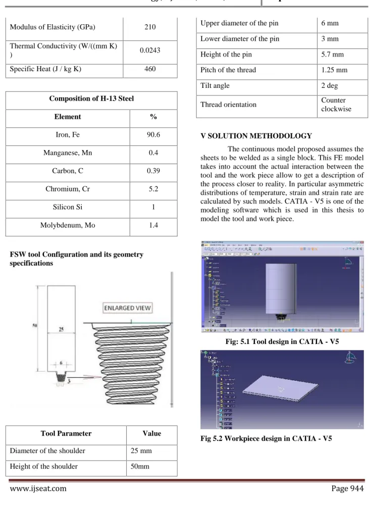
VI SIMULATION OF FSW USING DEFORM -3D
Fig 6.1 Meshed model in DEFORM-3D
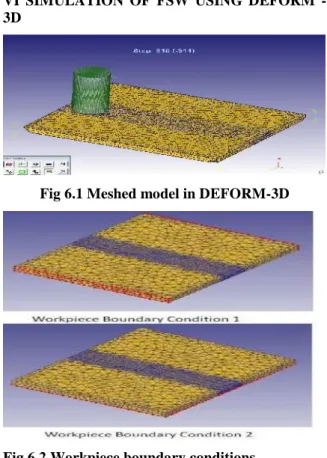
Fig 6.2 Workpiece boundary conditions Assign Plunging Movement to the tool:
Rotational speed= 1130 rpm
Plunging Speed = 2 mm / min
Simulation Steps Information
Starting Step number
-1(default for new problem)
Number of
simulation steps 415
Step increment
to save 10
Primary die FSW Tool
Time increment 1 sec
ANALYSIS OF AA2219 AND AA2014
Fig 6.3 Temperature distribution during plunging
Fig 6.4: Temperature distribution during welding step 1040
Fig 6.5: X- Direction temperature distribution
Fig 6.7 Longitudinal stress distribution during welding at 1340 rpm
Fig 6.8 Strain distribution during welding step 1944
Fig 6.9 Stress Vs Displacement graph
Mater ial Speed( rpm) Feed (mm/s ec) Load (N) CSA (sq.m m) Stress (N/mm 2) AA
2219 1340 11 9230 36 225.8
AA
2219 1130 11 7610 36 198.7
AA
2014 1340 11
1450
0 36 394.4
AA
2014 1130 11
1360
0 36 363.8
Table-1: Values recorded in the experiment (DACS-DELTA-UTM System)
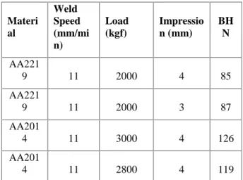
VII.BRINELL HARDNESS TEST
The Brinell method applies a predetermined test load (F) to a carbide ball of fixed diameter (D) which is held for a predetermined time period and then removed. The resulting impression is measured across at least two diameters usually at right angles to each other and these result averaged (d). A chart is then used to convert the averaged diameter measurement to a Brinell hardness number. Most typically, a Brinell test will use 3000 kgf load with a 10mm ball. If the sample material is aluminum, the test is most frequently performed with a 500 kgf load and 10mm ball. Brinell test loads can range from 3000 kgf down to 1 kgf. Ball indenter diameters can range from 10mm to 1mm. The test standard specifies a time of 10 to 15 seconds, although shorter times can be used if it is known that the shorter time does not affect the results.
Materi al Weld Speed (mm/mi n) Load (kgf) Impressio n (mm) BH N AA221
9 11 2000 4 85
AA221
9 11 2000 3 87
AA201
4 11 3000 4 126
AA201
4 11 2800 4 119
Table -2: Values from brinell hardness test VIII. CONCLUSION
The procedure reproduction is improved the situation rubbing blend welding for different welding parameters specifically apparatus rotational and transverse paces. The temperatures in the work piece are expanding with the expansion in instrument rotational speed while the temperatures are diminishing with increment in device navigate or welding speed. The most extreme temperatures are recorded at the areas near the blended zone and the temperature continues diminishing with increment in separate from the mixed zone.
It is important that leftover worry in FSW is low because of lower warm information and recrystallisation convenience of stress. A few test tests were welded with different blends of hardware rpm and welding speed for both the instrument geometries. Notwithstanding, it was watched that low device rpm brought about reliably low quality of welding. While, best outcomes were gotten with apparatus rpm of 1340 in conjunction with 11mm/min low weld speed.
This happened due to high instrument rpm with low weld speed caused extreme mechanical mixing of the metal making decrease in grain estimate driving higher quality of the welded joints.
Utilizing the consolidated plastic twisting and stream of the consumable joining bit and the mass of the keyhole, the FFSW procedure can repair the keyhole with both metallurgical and mechanical holding qualities, and the FSW crease can be accomplished without keyhole or different imperfections. The relative elasticity and stretching of the FFSW joint are 84.3 and 98.9% of the base weld without surrenders separately.
IX FUTURE SCOPE
Future research will keep on advancing the exploration of FSW, depending the comprehension of the complex physical associations which underlie a procedure that rose first as an innovation like.
Growing the materialness of FSW to a more extensive scope of building materials, propelling control systems for nonstop welding and spot welding, and creating novel FSW variations.
Assist examinations on the powers produced amid single and numerous goes for various combinations at various conditions and for various process parameters may be extremely valuable. Additionally studies might be done, considering the greater part of the welding parameters, on a more extensive scope of qualities. Weakness investigation, shear tests can be directed.
Higher thickness aluminum plates can be welded by utilizing twofold sided FSW. One can attempt to utilize instruments made of various materials to enhance the nature of the joints.
As the present weld is of butt joint, there is an extent of stretching out this work to the lap joints and examination should be possible between these two joints.
X REFERENCES
[1] J.C. McClure L.E. Murr A.C. Nunes M. Guerra, C. Schmidt. flow patterns during friction stir welding". Materials Characterization, 49, 2008.
[2] Simon Guerdoux Tracy Nelson Mohamed Assidi, Lionel Fourment. friction model for friction stir welding process simulation: Calibrations from welding experiments ". International Journal of Machine Tools Manufacture, 50, 2010.
[3] R. Kovacevic C.M. Chen. "finite element modeling of friction stir welding – thermal and thermomechanical analysis". ELSEVIER, 43, 2003.
[4] Yuang-Cherng Chiou Hung-Hsiou Hsu Yeong-Maw Hwang, Zong-Wei Kang. experimental study on temperature distributions within the workpiece during friction stir welding of aluminum alloys ". ELSEVIER, 48, 2008.
[5] C. Desrayaud J.H. Driver F. Montheillet-D. Allehaux P. Heurtier, M.J. Jones mechanical and thermal modelling of friction stir welding ". ELSEVIER, 171, 2006.
[6] V. Balasubramanian S. Rajakumar, C. Muralidharan. influence of friction stir welding process and tool parameters on strength properties of aa7075-t6 aluminium alloy joints". ELSEVIER, 32, 2011.
[7] F.W. Panella A. Squillace P. Cavaliere, R. Nobile. _mechanical and microstructural behaviour of 2014a€.7075 aluminium alloy sheets joined by
friction stir welding ". ELSEVIER, 46, 2006.