Low Frequency Modular Multilevel Converter Topology for Improved
Dynamic Performance of Variable-Speed AC Drives
N Bhargavi Prasanna*1, K N S K Santhosh2
M.Tech Student, Department of EEE, KIET-II, Kakinada, India.1 Asst. Professor, Department of EEE, KIET-II, Kakinada, India.2
Abstract- This venture shows a control conspire
for the particular multilevel converter (MMC) to drive a variable-speed air conditioning machine, particularly concentrating on enhancing dynamic execution. Hypothetically, the vitality adjust in the MMC cell capacitors is inclined to be unsteady at start-up and low-recurrence operations. Also, the MMC topology basically requires propelled control methodologies to adjust vitality and stifle the voltage throb of every phone capacitor. This venture proposes a control methodology for the powerful unique reaction of MMC even at zero yield recurrence utilizing leg balance voltage infusion. The leg counterbalance voltage for adjusting the arm vitality is delivered by direct figuring without the coursing current control circle controller. On account of the exceedingly unique leg balance voltage from direct computation and not traditional circling current controller, the dynamic execution of a MMC at low speeds has obviously made strides. The air conditioner machine has been driven from halt to evaluated speed without exorbitant cell capacitor voltage swells using this proposed technique. The reproduction comes about check that steady operation is ensured down to <2% of the evaluated speed under 40% stage stack torque unsettling influence. The size of converter yield voltages are expanded, utilizing fuzzy controller. The outcomes were broke down in MATLAB/SIMULINK condition.
Key words- MMC, AC drives, execution framework.
I.INTRODUCTION
A MODULAR multilevel converter (MMC) with concentrate on high-control medium voltage air conditioning engine drives is exhibited [1]–[10]. The utilization of a MMC makes it conceivable to spare cumbersome responsive parts in a medium-voltage engine drive application, for example, a line-transformer, consonant channel, and dc-connect reactor. Contrasted and regular medium voltage source converters, the MMC has a measured structure comprised of indistinguishable converter cells. Since it can without much of a stretch give higher number of voltage level for medium voltage applications, the nature of the yield voltage waveform is
better. Furthermore, as a result of the secluded structure it has focal points, for example, simple support and get together. Fig. 1 demonstrates the circuit arrangement of a MMC. This topology should be controlled by additional adjusting techniques. As appeared in Fig. 1, since the upper and lower arm streams move through cells in each arm, the comparing arm ebbs and flows cause principal intermittent throbs of cell capacitor voltages. The voltage throb of every cell's capacitor is for the most part influenced by the yield stage current and yield recurrence. Hypothetically, the size of the phone voltage variance is relative to extent of the yield stage current and contrarily corresponding to working recurrence [6]. Hence, uncommon exertion is requested to drive the air conditioner machine through MMC, which requires extensive beginning torque and low-speed unfaltering state operation. In late investigations of [7]–[9] and [16], the standards and calculations for air conditioning engine drives with the MMC have been presented. In any case, they didn't address the real control procedures, for example, changing yield recurrence, including halt and covering load torque aggravation. The vitality adjusting control is one of the principle issues of a MMC framework. In numerous literary works [6]–[10], the vitality adjusting controls of a MMC that utilizations flowing current control and regulation plan have been presented. The leg counterbalance voltage is utilized to manage the coursing current and has little impact on air conditioning and dc terminal voltages. The regular adjusting controls require the circling current controller that delivers the leg counterbalance voltage reference from the contribution of coursing current references utilizing the relative and fundamental (PI) or the corresponding and full controller. The execution of the flowing current controller effectsly affects the progression and unpredictability of the adjusting control. Hence, to enhance the adjusting execution by expanding data transfer capacity of the adjusting controller, this venture proposes an adjusting control strategy without the circling current controller. Accordingly, in the view purpose of capacitor voltage adjusting, the leg counterbalance voltage can be straightforwardly gotten with no stage delay because of the coursing current controller. Along these lines, the data transfer capacity of adjusting
Low Frequency Modular Multilevel Converter Topology for Improved
Dynamic Performance of Variable-Speed AC Drives
N Bhargavi Prasanna*1, K N S K Santhosh2M.Tech Student, Department of EEE, KIET-II, Kakinada, India.1 Asst. Professor, Department of EEE, KIET-II, Kakinada, India.2
Abstract- This venture shows a control conspire
for the particular multilevel converter (MMC) to drive a variable-speed air conditioning machine, particularly concentrating on enhancing dynamic execution. Hypothetically, the vitality adjust in the MMC cell capacitors is inclined to be unsteady at start-up and low-recurrence operations. Also, the MMC topology basically requires propelled control methodologies to adjust vitality and stifle the voltage throb of every phone capacitor. This venture proposes a control methodology for the powerful unique reaction of MMC even at zero yield recurrence utilizing leg balance voltage infusion. The leg counterbalance voltage for adjusting the arm vitality is delivered by direct figuring without the coursing current control circle controller. On account of the exceedingly unique leg balance voltage from direct computation and not traditional circling current controller, the dynamic execution of a MMC at low speeds has obviously made strides. The air conditioner machine has been driven from halt to evaluated speed without exorbitant cell capacitor voltage swells using this proposed technique. The reproduction comes about check that steady operation is ensured down to <2% of the evaluated speed under 40% stage stack torque unsettling influence. The size of converter yield voltages are expanded, utilizing fuzzy controller. The outcomes were broke down in MATLAB/SIMULINK condition.
Key words- MMC, AC drives, execution framework.
I.INTRODUCTION
A MODULAR multilevel converter (MMC) with concentrate on high-control medium voltage air conditioning engine drives is exhibited [1]–[10]. The utilization of a MMC makes it conceivable to spare cumbersome responsive parts in a medium-voltage engine drive application, for example, a line-transformer, consonant channel, and dc-connect reactor. Contrasted and regular medium voltage source converters, the MMC has a measured structure comprised of indistinguishable converter cells. Since it can without much of a stretch give higher number of voltage level for medium voltage applications, the nature of the yield voltage waveform is
controller in light of the immediate voltage infusion technique can be expanded more than that in view of the circling current controller. What's more, the distinction between the cell voltages can be diminished quicker. Therefore, from the viewpoint of the control flow and control unpredictability, the proposed leg balance voltage infusion strategy is preferable and more straightforward over the ordinary circling current infusion technique. Moreover, the infusing recurrence of leg counterbalance voltage infusion strategy can be expanded more than that of current infusion technique, in view of the developed data transfer capacity of the proposed technique. Consequently, attributable to the high-recurrence infusion with the proposed strategy, the variance of cell capacitor voltage can be limited contrasted and circling current infusion technique. The objective of this venture is to propose a control procedure of the whole recurrence extend operation including stop for variable speed air conditioning engine drive. The proposed strategy decreases the control execution debasement of the MMC when the heap torque suddenly changes. The control plot presents two operation modes: 1) a low-recurrence mode for start-up and low-speed operation and 2) an ordinary recurrence mode from medium to higher speed operation. The procedure in the low-recurrence mode abuses leg counterbalance voltage and basic mode voltage with the high-recurrence part to stifle the cell capacitor voltage swell. The square wave voltage is utilized as the leg balance voltage, which demonstrates that the coursing current pinnacle is diminished when contrasted and sinusoidal waveform of the voltage [7]. A switchover strategy between two operation modes is depicted to drive the air conditioner machine in the general speed locale. To demonstrate the adequacy of the proposed control procedures, a 12-kV 24-MVA MMC-based flexible engine drive framework was outlined utilizing the MATLAB programming. The reproduction results could offer the possibility and favorable position of the contrived technique for high-control medium voltage drives with MMC. Also, tests for variable-speed air conditioning engine drives by a 10-kVA model MMC imitating fans, blowers, or pump drive framework were performed to check the practicality of the proposed adjusting system. The analyses were directed for looking at elements of the sinusoidal and square wave leg counterbalance voltage. The steady operation at 1 Hz, which is <2% of the evaluated speed, is appeared under an unexpected stride stack torque unsettling influence from 0% to 40% to exhibit the dynamic execution. The reproduction comes about demonstrate that all control procedures was very much fused in the variable-speed air conditioning engine drive framework with a heap where the torque differs in relative to the square of the speed, similar to fans, blowers, or pumps.
MODELING OF PROPOSED THEORY
II. CONFIGURATION AND BASIC PRINCIPLE OF
THE MMC
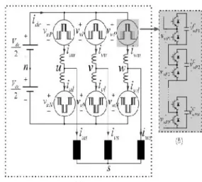
Fig. 1(a) shows the circuit configuration of the MMC. The three-phase MMC is composed of three legs and each leg has two arms and two arm inductors. Each arm has cascaded N-identical half-bridge circuit-based cells, and each cell consists of one dc capacitor and two active switching devices.
Block diagram:
Fig. 1. Circuit configuration of the MMC
The cascaded cell modules are shown in Fig. 1(b) in detail. In Fig. 1(a), ixu and ixl are the upper and lower arm currents, respectively, and ixs is the output phase current where x’ represents the u-, v-, or w-phase.
The output phase current, ixs, and circulating current, ixo, are calculated from the upper and lower arm currents described in (1) and (2). Therefore, the arm currents can be deduced as (3) and (4), according to the decoupled control scheme in [8] and [11]
c = i − i (1)
i = (2)
i = + i (3)
i = − + i (4)
phase voltage, which is vxs = Vmcos(ωst). A detailed mathematical description of the relationships in an MMC is given in [10]
v = (R + L )i (5) v∗ = − v∗ − v∗ − v∗ (6)
v∗ = + v∗ + v∗ − v∗ (7)
The instantaneous power of each arm in the x-phase can be deduced as (8) and (9). These two equations must be considered to understand of the proposed balancing control
P = v∗ i = − v∗ − v∗ − v∗ + i
(8)
P = v∗ i = + v∗ + v∗ − v∗ − + i
(9)
In addition, the upper and lower arm energy can be calculated by (10) and (11), respectively. Each arm energy is the sum of the cell capacitor energies in the corresponding arm at x-phase leg
E = C ∑ (v p ) (10)
E = C ∑ (v N ) (11)
III. PROPOSED BALANCING CONTROL S
CHEME
A. Start-Up and Low Frequency Mode
The capacitor power difference between the upper and lower arm, which is derived as (12) from (8) and (9), affects the cell capacitor voltage balance of the
arms. The first two
terms on the right-hand side in (12), 0.5Vdcixs−2vxs∗ixo,
have considerable dc or very low-frequency components. Thus, when the output frequency is dc or very low, the voltage
difference between the arms will diverge due to this low frequency term
P − P = 0.5V i − 2v∗ i − v∗ i (12)
To balance the power difference between arms, a control strategy exploiting the common mode voltage, vsn, was used in this project. The common mode voltage can be regarded as an additional degree of freedom for controllability since the common mode voltage does not affect the line-to-line output voltage. It is natural to select the frequency of the common mode voltage as a high frequency to minimize the cell capacitor voltage fluctuations. In addition, since the circulating current, ixo, is also a controllable element that does not affect the
output phase current, a high-frequency component can be superimposed on the circulating current. Hence, the third term on the right-hand side in (12), 2v∗snixo can be used to balance the power of arms with the high frequency components in vsn and ixo. For convenience, the low- and high-frequency elements can be segregated from
ixo and vsn as (13) and (14), where ~ and ^ refer to the
low and high-frequency components, respectively
i = ı̃ + ı̂ (13)
v = v (14)
The power difference between the upper and lower arms can be rearranged from (12) to (14), and then, the low-frequency power component can be extracted as in (15).
Here, the power
difference should be controlled as null
To nullify the low-frequency component as in (15), the low-frequency component of 2vˆsn∗ iˆxo∗ should be controlled. Thus, vˆsn∗ and iˆxo∗should be regulated as the same high frequency, to make the power term of 2vˆsn∗ iˆxo∗ have dc or low frequency component. In the case of the sinusoidal leg offset voltage injection method, vˆ∗sn and vˆxo∗can be defined as (16) and (17), andωh refers to the angular speed of the high-frequency component, Vsn for the effective value of common mode voltage, and V˜xo for the magnitude of high-frequency leg offset voltage, which may have dc and several low-frequency components
v∗ = √2 cos( ) (16)
v∗ = cos( + ∅) (17)
The phase angleφin (17) between the leg offset voltage and circulating current is derived from (18) to make the circulating current synchronize with the common mode voltage
∅ = (18)
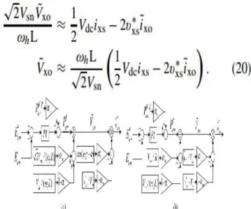
And then, 2vˆsn∗ iˆxo∗ in (15) can be substituted with (19). The magnitude of high-frequency leg offset voltage,
V˜xo, can be calculated as
Fig. 2. Proposed control scheme for variable-speed drives. (a) Sinusoidal wave voltage injection method. (b) Square wave voltage injection method.αWis weighting factor for switchover, which is described in Section III-C.
In the case that the sinusoidal wave voltage is injected to both the common mode and the leg offset voltage, the balancing control strategy is shown as a block diagram in Fig. 2(a). Eerr is the energy difference between the upper and lower arms as in (21). Eerr∗is the reference of energy difference and should be set as null to keep the balance of the arm energies
E = E − E = C (v p ) − ∑ (v N ) (21)
PVff err in Fig. 2(a) can be derived as (22) by (20)
P = V i − 2v∗ ı̃ (22)
In the case of the square leg offset voltage injection, on the other hand, the square wave voltage can be injected to both the common mode and the leg offset voltage as
shown in Fig. 2(b). In this case, vˆsn∗ can be defined by (23) and fh stands for the frequency of the injected high-frequency voltage
v∗ = −v 0 ≤ t <
v ≤ t < (23)
Under the assumption that the arm resistance, R, is dominant during each given quasisteady half period, 1/(2
fh), vˆxo∗can be approximated as (24) from (5), (15), and (23)
PVff err in Fig. 2(b) can also be derived from (22) using
(24) similarly with the case of sinusoidal wave. B. Normal Frequency Mode
Since the output frequency is high enough in the normal frequency mode, the voltage fluctuation of the cell capacitor is tolerable. In this mode, the circulating current is controlled to have only dc component to minimize the conduction loss caused by the additional circulating current. As the operation frequency increases, meanwhile, the margin of the common mode voltage decreases. Hence, the common mode voltage is less available for balancing control. Practical MMC systems may have an inherent unbalance due to slight asymmetries in cells, structural errors, and other
Fig. 3. Relationship between operating frequency and weighting factor.
Issues. In normal frequency mode, therefore, it should be performed just to eliminate the inevitable small dc unbalances. The balancing can be achieved using the
circulating current
as 2v∗xsixo in (12). By regulating the leg offset voltage for circulating current to have fundamental frequency component, this dc unbalance can be suppressed.
C. Switchover Between Two Modes
output frequency of MMC. A switchover tactic between the low- and high-frequency modes shown in Fig. 3 is devised by the weighting factor, αW. In addition, this factor is applied to the switchover of the balancing control scheme shown in Fig. 2. In addition, the tactic would have the hysteresis band to prevent chattering in the vicinity of the switchover frequency, fcut.
IV. OVERALL CONTROL S CHEME FOR ENTIRE FREQUENCY OPERATION
Fig. 4 shows the overall controller for the entire frequency operation from standstill to normal frequency mode. First, the averaging controller carries out regulating the leg power, which is the difference between dc-link input power and ac output power. The leg power is calculated as (25) by adding (8) and (9)
P + P ≈ V I − 2v∗ ı̃ − v∗ i (25)
Fig. 4. Proposed overall control scheme for variable-speed drives
Because the low-frequency power component in (25) should be nullified as in (26), the controller output has dc and second order harmonic frequency components as described in (27)
P + P ≈ V ı̃∗ − v∗ i = 0 (26)
ı̃∗ = v∗ i /V (27)
E leg is the energy of the leg and it can be calculated as
(28). E∗ leg is the reference energy of the leg as (29), where vc∗is the reference value of cell capacitor voltage,
Vdc/N
E = E + E = C ∑ (v p ) + ∑ (v N ) (28)
E∗ = 4N V∗ = NC V∗ (29)
The feed-forwarding power term, PlegV ff, can be derived as v∗xsixs from (27). Therefore, the PI controller can simply be adopted as the circulating current controller for the averaging control. The details about the averaging
controller are described in [10]. Meanwhile, the balancing controller can be chosen between two schemes in Fig. 2 that are namely, the sinusoidal and the square wave voltage injections. As shown in Fig. 4, the balancing controller directly makes the leg offset voltage without the circulating current controller to eliminate the energy difference between upper and lower arms. By reason of this fact, the balancing controller has a wider bandwidth, and can achieve a better transient response compared with the control scheme based on the inner circulating current. Finally, the upper and lower arm voltage references are synthesized as (6) and (7), which are composed of vxs∗ from the output of phase current controller, vxo∗from the
averaging and
balancing controller, and the injected common mode voltage of vˆ∗sn.
V. FUZZY CONTROLLER
The word Fuzzy means vagueness. Fuzziness occurs when the boundary of piece of information is not clear-cut. In 1965 Lotfi A. Zahed propounded the fuzzy set theory. Fuzzy set theory exhibits immense potential for effective solving of the uncertainty in the problem. Fuzzy set theory is an excellent mathematical tool to handle the uncertainty arising due to vagueness. Understanding human speech and recognizing handwritten characters are some common instances where fuzziness manifests.
Fuzzy set theory is an extension of classical set theory where elements have varying degrees of membership. Fuzzy logic uses the whole interval between 0 and 1 to describe human reasoning. In FLC the input variables are mapped by sets of membership functions and these are
called as “FUZZY SETS”.
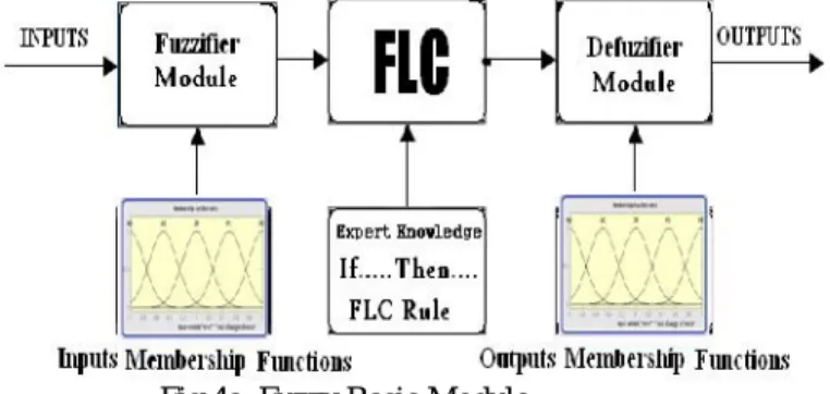
Fuzzy set comprises from a membership function which could be defines by parameters. The value between 0 and 1 reveals a degree of membership to the fuzzy set. The process of converting the crisp input to a fuzzy value
is called as “fuzzificaton.” The output of the Fuzzier module is interfaced with the rules. The basic operation of FLC is constructed from fuzzy control rules utilizing the values of fuzzy sets in general for the error and the change of error and control action. Basic fuzzy module is shown in fig.6. The results are combined to give a crisp output controlling the output variable and this process is
called as “DEFUZZIFICATION.”
SIMULINK MODELLING AND RESULTS VI. SIMULATION RESULTS
To verify the effectiveness of the proposed control strategy, an adjustable speed drive system based on 12-kV 24-MVA
6.1 Simulink modeling diagrams:
6.1 Block diagram of modular multilevel converter
6.2 Block diagram of PI controller strategy
6.3 Sub system of controller(u phase)
6.2 FUZZY CONTROLLER BLOCK DIAGRAMS
6.4 fuzzy controller simulation diagram
Fuzzy controller
MMC has been implemented using the time-domain simulation program, MATLAB. The number of cells in each arm, N, equals 20. Thus, the system with 120 cells
was simulated. Each
cell capacitor voltage is controlled as 600 V, and the cell is composed of the half-bridge inverter and the cell capacitance is 6000μF. The nearest level modulation is applied to generate the arm voltage references and reduce the switching loss of MMC [15]. The cell voltage sorting algorithm is applied to the cell voltage balancing [14]. The parameters used in the simulation are listed in Table I. It is assumed that the 21-level MMC system drives a 20 MW 20-pole permanent magnet synchronous machine (PMSM) with adjustable mechanical load. The PMSM parameters are summarized in Table II. From the simulation results the devised method can be applied to high-power medium voltage adjustable drive system
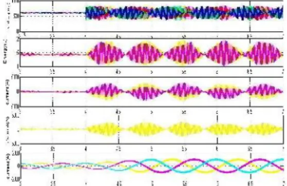
Fig. 5. Simulation waveform when applying the proposed leg offset voltage injection method with 6r/min speed and step load torque from 10% to 40% of the rated torque. (a) Sinusoidal waveform offset voltage injection. (b) Square waveform offset voltage injection.
injection and proposed leg offset voltage injection methods, the bandwidth for the balancing controller of the torque two methods is set as the same, and the frequency of the injected component was also set as the same, 100 Hz.
Fig. 6. Simulation waveform when applying the conventional circulating current injection method with 6 r/min speed and step load torque from 10% to 36% of the rated The magnitude of the step load torque applied at the conventional current injection method is 36% of the rated torque, which is less than the proposed method test in Fig. 5. As shown in Fig. 6, the system based on the conventional method becomes unstable and stalls in a moment at the end. After the abrupt step load torque is applied at 4 s, the cell capacitor voltage fluctuations are larger than the fluctuations when using the leg offset voltage injection method in Fig. 5.
CONCLUSION
In this project, a control strategy for variable-speed ac motor drives based on MMC has been presented. To overcome the difficulties of the power balance between cells and arms of MMC over wide operation speed ranges, a direct leg offset voltage injection method has been devised. Utilizing the proposed method, the ripple voltage of each cell of MMC has been kept within allowable bounds under the sudden application of 40% of rated load torque at the extremely low frequency, 1 Hz, which is <2% of rated frequency. Based on the simulation and experimental results, it can be noted that the control performance of the upper and lower arm energy ripple by the proposed leg offset voltage injection method is better than that by the conventional circulating current injection method with the inner loop. In addition, the variable speed ac motor drive has been proven to work based on the switchover tactic by testing the overall speed including standstill. The magnitude of converter output voltages are increased, using fuzzy controller. The results were analyzed in MATLAB/SIMULINK environment.
REFERENCES
[1]Jae-Jung Jung, Student Member, IEEE, Hak-Jun Lee,
Student Member, IEEE, and Seung-Ki Sul, Fellow, IEEE
“Control Strategy for Improved Dynamic Performance of Variable-Speed Drives With Modular Multilevel Converter”
[2] A. Lesnicar and R. Marquardt, “An innovative
modular multilevel converter topology suitable for a wide
power range,” inProc. IEEE Power Tech Conf., Bologna,
Italy, Jun. 2003.
[3] M. Hiller, D. Krug, R. Sommer, and S. Rohner, “A
new highly modular medium voltage converter topology
for industrial drive applications,” inProc. 13th Eur. Conf. Power Electron. Appl., Sep. 2009. pp. 1–10.
[4] G. P. Adam, O. Anaya-Lara, G. M. Burt, D. Telford,
B. W. Williams, and J. R. McDonald, “Modular
multilevel inverter: Pulse width modulation and capacitor
balancing technique,”IET Power Electron., vol. 3, no. 5,
pp. 702–715, Sep. 2010.
[5] A. Antonopoulos, K. Ilves, L. Angquist, and H.-P. Nee,“On interaction between internal converter dynamics
and current control of high-performance high-power AC
motor drives with modular multilevel converters,” in
Proc. IEEE ECCE, Sep. 2010, pp. 4293–4298.
[6] M. Hagiwara, K. Nishimura, and H. Akagi, “A
medium-voltage motor drive with a modular multilevel
PWM inverter,” IEEE Trans. Power Electron., vol. 25,
no. 7, pp. 1786–1799, Jul. 2010.
[7] M.Hagiwara,I.Hasegawa,and H.Akagi,“Start-up and low-speed operation of an electric motor driven by a modular multilevel cascade inverter,”IEEE Trans.Ind.
Appl.,vol.49,no.4,pp.1556–1565,Jul./Aug.2013.
[8] J. Kolb, F. Kammerer, and M. Braun, “Straight
forward vector control of the modular multilevel converter for feeding three-phase machines over their complete frequency range,” in Proc. 37th Annu. Conf. IEEE Ind. Electron. Soc. IECON, Nov. 2011, pp. 1596–