CHARACTERIZING AND UTILIZING A CHEMICAL IONIZATION MASS SPECTROMETER (CIMS) AS A METHOD TO ESTIMATE SECONDARY ORGANIC AEROSOL YIELDS FROM ISOPRENE-DERIVED EPOXIDES
Wendy Jane Marth
A thesis submitted to the faculty of the University of North Carolina at Chapel Hill in partial fulfillment of the requirements for the degree of Master of Science in the Department of Environmental Science and Engineering.
Chapel Hill 2013
Approved by:
Dr. Jason Surratt
Dr. Ken Sexton
ii
ABSTRACT
WENDY JANE MARTH: Characterizing and Utilizing a Chemical Ionization Mass Spectrometer (CIMS) as a Method to Estimate Secondary Organic Aerosol
Yields from Isoprene-Derived Epoxides (Under the direction of Jason Surratt)
Isoprene is the most abundant non-methane hydrocarbon emitted into
Earth’s atmosphere and although recognized as the single largest source of
global secondary organic aerosol (SOA), the exact manner in which
isoprene-derived SOA is formed remains unclear. Recently, epoxides produced from
isoprene oxidation have been shown to be critical in SOA formation. In this work
an acetate chemical ionization mass spectrometer (CIMS) was characterized and
utilized to measure SOA yields from two proposed isoprene-derived epoxides,
isoprene epoxydiol (IEPOX) and methacrylic acid epoxide (MAE) under varying
particle acidities. The resulting SOA yield and CIMS characterization showed the
kinetics associated with MAE uptake is likely slower then IEPOX, but results for
IEPOX were promising. This work also resulted in a much better understanding
of the acetate CIMS operation and showcased its ability to measure these
epoxides in real time.
To my parents, Timothy and Michele Marth, for their enduring encouragement, love and support and to Jonathan Gardow, who has supported me through numerous long days and late nights and always encouraged me to stay true to
iv
ACKNOWLEDGEMENTS
TABLE OF CONTENTS
LIST OF TABLES ... VII
LIST OF FIGURES ... VIII
LIST OF ABBREVIATIONS AND SYMBOLS ... ix
1. INTRODUCTION ... 1
2. CHARACTERIZATION OF AERODYNE CIMS ... 8
2.1 Set-Up and Operation of an Aerodyne Chemical Ionization-Time-of-Flight Mass Spectrometer (CI-TOF-MS) ... 8
2.2 CIMS Results and Discussion ... 12
2.2.1 Control Experiments ... 12
2.2.2 Gas-Phase Calibrations and Quantifications ... 13
2.2.3 In-Line Aerosol Filter Experiments ... 15
2.2.4 Sampling Line Material ... 16
2.2.5 Epoxide with Subsequent Injection of Aerosol Experiments ... 17
2.2.6 General Observations ... 19
2.3 CIMS Conclusions ... 22
3. CALCULATION OF SOA YIELDS FROM REACTIVE UPTAKE OF IEPOX ... 24
3.1 IEPOX Experimental Set-up ... 24
3.2 IEPOX Results and Discussion ... 25
vi
4. CALCULATION OF SOA YIELDS FROM REACTIVE UPTAKE
OF MAE ... 29
4.1 MAE Experimental Set-up ... 29
4.2 MAE Results and Discussion ... 30
4.3 MAE Conclusions ... 32
5. FUTURE WORK AND ATMOSPHERIC IMPLICATIONS ... 34
TABLES ... 36
FIGURES ... 38
APPENDIX I REAGENT ION SET-UP AND PARTS LIST ... 49
APPENDIX II PICTURES OF EXPERIMENTAL SET-UP OF CIMS ... 51
APPENDIX III CIMS START-UP PROCEDURE ... 53
LIST OF TABLES
Table 1 Operational voltages and settings for TOF ... 36
Table 2 IEPOX yield results ... 36
viii
LIST OF FIGURES
Figure 1 Low-NO regime isoprene reaction mechanism ... 38
Figure 2 High-NO regime isoprene reaction mechanism ... 38
Figure 3 Aerodyne CIMS schematic ... 39
Figure 4 CIMS time traces for gaseous MAE and gaseous IEPOX ... 40
Figure 5 IEPOX and MAE calibration by addition time traces ... 41
Figure 6 MAE and IEPOX calibration curves ... 42
Figure 7 Gaseous MAE and IEPOX time traces without and with a PTFE filter ... 43
Figure 8 Nitric acid and corresponding MAE time traces for nylon and PTFE sampling lines ... 43
Figure 9 Acidic Seed + 25ppbv MAE and Neutral Seed + 25ppbv MAE experiment time traces ... 44
Figure 10 25 ppbv MAE and 25 ppbv IEPOX only experiments followed by the addition of acidic or neutral seed ... 44
Figure 11 Acetate signal after carboxylic acid addition and after a pressure change ... 45
Figure 12 Average mass spectrum of clean and contaminated reagent ion system ... 45
Figure 13 Acetate warm up times ... 46
Figure 14 Chemical structure of β-IEPOX ... 46
Figure 15 Seed + 25ppbv IEPOX plots ... 47
Figure 16 Chemical structure of MAE ... 47
LIST OF ABBREVIATIONS AND SYMBOLS
Acidic Seed I: 0.06 M MgSO4 + 0.06 M H2SO4 (aq)
Acidic Seed II: 0.09 M MgSO4 + 0.03 M H2SO4 (aq)
BSQ: big segmented quadrupole
CI: chemical ionization
CIMS: chemical ionization mass spectrometer
cps: counts per second
DMA: differential mobility analyzer
HC: hydrocarbon
IEPOX: isoprene epoxydiol
IMR: ion-molecule reaction region
MAE: methacrylic acid epoxide (2-methyloxirane-2-carboxylic acid)
MCP: microchannel plate
MCPC: mixing condensation particle counter
MPAN: methacryloylperoxynitrate
MS: mass spectrometer
NO: nitrogen oxide
NOx: nitrous oxides
NO2: nitrogen dioxide
OH: hydroxyl radical
PM: particulate matter
PTFE:poly(1,1,2,2-tetrafluoroethylene)
x
SEMS: scanning electrical mobility spectrometer
SO2: sulfur dioxide
SOA: secondary organic aerosol
SSQ: short segmented quadrupole
TOF: time-of-flight
UMR: unit mass resolution
1. INTRODUCTION
Organic compounds contribute a large fraction (i.e., 20–90%) towards the
total mass of tropospheric fine particulate matter (PM2.5, with aerodynamic
diameter ≤ 2.5 µm) (Kanakidou et al., 2005; Kroll and Seinfeld, 2008; Hallquist et
al., 2009). High concentrations of PM2.5 are known to have adverse human
health effects (Pope III et al., 2006) and play a role in global climate change
(Kanakidou et al., 2005; Hallquist et al., 2009). Although there are many sources
for organic compounds found in PM2.5, which includes primary emissions (e.g.,
biomass burning events or diesel engine exhaust), secondary organic aerosol
(SOA) formation often accounts for a large, and at times, dominant fraction of the
organic mass found in tropospheric PM2.5 (Hallquist et al., 2009). SOA has been
traditionally viewed to form in the troposphere from the oxidation of volatile
organic compounds (VOCs), where the resultant low-vapor pressure oxidation
products partition between the gas and aerosol phases.
Detailed chemical characterization of both laboratory-generated and
ambient organic aerosol using advanced off-line and on-line mass spectrometric
techniques has been critical to the discovery of previously unidentified sources of
SOA over the last 5 years (Hallquist et al., 2009, and references therein; Surratt
et al., 2006, 2007ab, 2008, 2010). Recent identification of high-molecular-weight
(MW) species, such as oligomers and organosulfates, using these techniques
2
by the volatility of the gas-phase products formed, but is also influenced by the
preference of certain degradation products to undergo further reactions in the
particulate phase (Denkenberger, et al., 2007; Docherty et al., 2005; Gao et al.,
2004; Iinuma et al., 2004, 2007ab; Kalberer et al., 2004; Suratt et al., 2006,
2007ab, 2008, 2010; Tolocka et al., 2004; Tobias and Ziemann, 2000). This has
substantially altered perceptions of which emitted VOCs can act as SOA
precursors, such that SOA formation from the degradation of smaller VOCs can
no longer be automatically disregarded; for example, even volatile glyoxal can
associate with other aldehydes, organic acids, and amines/amino acids already
present in particles to add to SOA mass (DeHaan et al., 2009; Jang et al., 2002;
Kroll et al., 2005; Volkamer et al., 2007), or can be sulfated after gem-diol
formation (Surratt et al., 2007a, 2008; Gómez-González et al., 2008).
Additionally, recent laboratory on-line aerosol mass spectrometry (AMS)
measurements have shown that photochemical aging of semivolatile organic
compounds in diluted biomass-burning plumes and diesel exhaust produces
significant amounts of SOA not previously accounted for in models (Grieshop et
al., 2009ab; Robinson et al., 2007). Another important development emerged
from the chemical analyses of aerosol filter samples collected from both the
Amazon basin and laboratory photooxidation experiments of isoprene by gas
chromatography (GC)/MS with prior derivatization, which lead to the recognition
that isoprene (2-methyl-1,3-butadiene, C5H8), a compound previously thought to
also produce SOA in potentially significant quantities due to its large emission
strength (Claeys et al., 2004; Kroll et al. 2006; Surratt et al., 2006, 2010).
Although the application of both off-line and on-line advanced analytical
techniques have increased our understanding of SOA formation pathways in
recent years, current models predict notably less SOA mass than is typically
observed in the atmosphere (de Gouw et al., 2005, 2008; Heald et al., 2005;
Volkamer et al., 2006). A large source for this underestimation is the lack of full
chemical characterization of organic constituents found in both the gas and
aerosol phases, likely resulting in significant sources of SOA not being identified
or well characterized, and thus, not included in current SOA models (Hallquist et
al., 2009; and references therein). Much of the current research efforts in the
community are now focused on trying to identify this missing source of SOA
(Hallquist et al., 2009).
Recent work has shown that isoprene SOA is enhanced by higher ratios of
NO2/NO, resulting in oligoester formation from isoprene (Chan et al., 2010;
Surratt et al., 2010), as well as by increased aerosol acidity (Surratt et al., 2010;
Lin et al., 2012). Interestingly, recent remote sensing data from the southeastern
U.S. region has shown that biogenic VOC emissions combine with anthropogenic
pollutants to form substantial amounts of PM (Goldstein et al., 2009). When
incorporating many of the newly identified chemical reactions that lead to the
enhancement of biogenic SOA by anthropogenic pollutants into the EPA air
4
biogenic SOA in the eastern U.S. can be controlled by decreasing anthropogenic
pollutant emissions.
Isoprene is a substantial contributor to the global SOA burden, with
implications for public health and the climate system. The mechanisms by which
isoprene-derived SOA is formed and the influence of environmental conditions,
however, remain unclear.
It has been demonstrated that the reactive uptake of gaseous isoprene
epoxydiol (IEPOX) is critical to the formation of isoprene SOA under low-NO and
acidic conditions (Surratt et al., 2010; Froyd et al., 2010; Lin et al., 2013). The
detailed chemical mechanism is shown in Figure 1. Chemical ionization mass
spectrometry (CIMS) techniques using CF3O– reagent ion chemistry were critical
for the identification of the formation of gaseous IEPOX under low-NO conditions
(Paulot et al., 2009; Surratt et al., 2010). However, real-time gas-phase analysis
has been lacking in previous SOA studies (Hallquist et al., 2009) and is
something that needs further exploration, especially if SOA formation
mechanisms are going to be more fully characterized.
Benefits of using CIMS to detect atmospheric species include the ability to
detect oxygenated volatile and semi-volitle organic species in real time. This is
something that GC/MS and GC/FID techniques have not generally lent
themselves well to in the past. The ability to detect these organic species in a
time frame on the order of seconds is crucial when the overall goal is to
understand the kinetics and mechanism of potentially reactive species. CIMS is
spectrometry (PTR-MS), and is just now gaining more attention by atmospheric
chemists. Paulot et al. (2009) was one of the first groups to utilize CIMS to study
SOA formation pathways. Other reagent ion CIMS also include iodide (I-), H3O+,
and acetate and have been used by groups such as Slusher et al. (2004), Wolfe
et al. (2007), Sellegri et al. (2005), and Bertram et al. (2011), respectively. All
reagent ion chemistries work similarly in that they react with molecules of interest
to charge them so they are then detectable in a mass spectrometer, while they
differ in specificity. Acetate CIMS specifically targets and ionizes small organic
acids (Veres et al. 2008) and possibly other diol species, and for this reason will
likely be useful in trying to elucidate isoprene-derived SOA reaction mechanisms.
In the presence of high levels of nitrogen oxides (NOx = NO + NO2), typical
of urban atmospheres, the adduct of hydroxyl radical (OH) with
methacryloylperoxynitrate (MPAN) has been identified as the transient
(HOMPAN) leading to isoprene SOA formation, but subsequent steps in the
pathway remain unknown (Surratt et al., 2010). Recent work by Lin et al. (2013)
demonstrated that gaseous methacrylic acid epoxide (MAE) likely forms from the
rearrangement of the HOMPAN adduct and then partitions to the particle phase
and undergoes subsequent reactions to form isoprene-derived SOA. The
detailed chemical mechanism of this proposed route is shown in Figure 2.
Due to the complexity of organic aerosol, it is often challenging to
determine its precursor(s) and therefore difficult to incorporate them into global
models to accurately estimate SOA burden. Using a fractional approach,
6
gas (ROG) that is converted to aerosol can more easily be incorporated into
models. Yield is calculated by dividing the change in organic aerosol mass
(ΔMo) measured, by the amount of ROG reacted (in µg/m3) (Odum et al. 1996).
The benefit to using this approach is that it makes SOA production easier to
incorporate into models since it simplifies the reactions that lead to SOA by just
using the precursor, and not explicit intermediates or products. This also
drastically cuts down on computing time, which can be an issue when working
with large-scale global models. For SOA produced by the low-NO and high-NO
reaction pathways, current models use an isoprene SOA yield of 3% and 1-2%,
respectively. However, when using these yields, current models under predict
the amount of isoprene SOA in areas impacted by both isoprene and
anthropogenic emissions (Carlton et al., 2010). These yields that have been
previously calculated assume complete reactions with the gas-phase, which
although a good first step, is something the use of CIMS technology can help us
determine and improve yield determinations.
The aim of this thesis is to characterize and utilize a newly acquired
Aerodyne Chemical Ionization Mass Spectrometer (CIMS) equipped with acetate
reagent ion chemistry to elucidate both the gas- and aerosol-phase chemistries
associated with isoprene SOA formation. As a first step in characterizing this
new instrument, we examine whether SOA yields can be determined from
reactive uptake of synthetic IEPOX and MAE, proposed isoprene-SOA
intermediates, onto varying seed aerosol types (i.e., neutral vs. acidic aerosol).
more accurately predict SOA formation from isoprene-derived epoxides. During
this initial application of acetate CIMS, better characterization of its performance
and behavior has been obtained, which is critical in understanding how the mass
spectral data can be used to understand the chemical system under investigation
2. CHARACTERIZATION OF AERODYNE CIMS
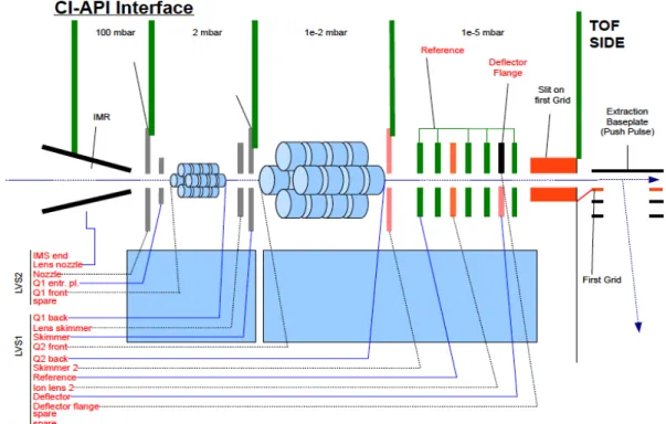
2.1 Set-Up and Operation of an Aerodyne Chemical Ionization-Time-of- Flight Mass Spectrometer (CI-TOF-MS)
In October 2011, the Surratt lab’s new chemical ionization high-resolution
time-of-flight mass spectrometer (CI-HR-TOFMS) (Aerodyne Research, Inc.,
Billerica, MA, Serial #005) (HTOF, TOFWERK AG, Switzerland), or more
commonly referred to as CIMS, arrived. The CIMS uses a HR-TOF MS and has
the capabilities of detecting gas-phase species as either positive or negative ions.
The goal in using this instrument was to detect and quantify species that are
thought to be precursors of isoprene-derived SOA and help to identify gas-phase
organics found in complex mixtures. Combining this instrument with that of a
scanning electrical mobility spectrometer (SEMS) (Brechtel Manufacturing, Inc.,
Hayward, CA) produces both real-time gas- and particle-phase data, respectively,
and thus, SOA yields can be calculated experimentally.
The Aerodyne CIMS was designed to allow a variety of chemical
ionization schemes to be used interchangeably with this instrument and is
described in detail elsewhere (Bertram et al., 2011; Yatavelli et al., 2012). A
schematic of the CIMS instrument is shown in Figure 3; flow into the instrument
starts at the IMR (ion-molecule reaction region) where molecules react and
series of charged plates and though two quadrupoles that act as RF-only guides.
Ions are transmitted through the primary beam and then enter the TOF region of
the CIMS to be high resolution mass separated. From there, ions travel to an
MCP detector and the resulting electrical signals are converted into a signal that
corresponds to each different mass. When the instrument was delivered to UNC
a CI source was not included, and thus, a CI source using acetate ion chemistry
was fabricated. A detailed schematic for the set-up of the fabricated CI source
and a list of parts needed to build it are included in Appendix I.
As an overview, negative ion mode acetate-CI works by abstracting a
hydrogen atom from the organic acid or by adding an acetate molecule to the
organic. The organic acid or non-acidic organic is then detected as [M-H]- or
[M+acetate]- ion, respectively. All of this is achieved by flowing gaseous acetic
anhydride and nitrogen though an alpha emitter, such as 210Po, where an
electron is abstracted from an N2 molecule. This electron then charges and
excites an acetic anhydride molecule, upon collision with another molecule, M,
the excited molecule fragments into acetate and acetyl. Acetate ion is introduced
to the sample in the IMR region of the CIMS where it then can undergo acid-base
reactions with organic acids or can form clusters with non-acidic organics,
depending on the pressure and transmission settings of the mass spectrometer.
These reactions mentioned above are described in detail by Bertram et al. (2011)
and is the basis for negative ion mode acetate CIMS. It is important to note that
the gas-phase acidities of the ions of interest must be greater than that of acetic
10
The CIMS was positioned on the bench top to be as close as possible to
the chamber sampling port and was not moved from this position once running,.
All external pumps not connected to the CIMS frame were installed on the floor to
reduce vibrations on the bench top. The instrument computer, power supply, and
uninterruptable power supply were mounted into a 19” rack mount also located
on the bench top. The CIMS turbo pump (three stage differential pump, Pfeiffer)
was always operated in “standby” as it maintained low enough pressure in the
TOF region of the CIMS, while maintaining a lower speed. The CIMS was
connected directly to the indoor chamber using ¼” PTFE tubing or in some cases
¼” nylon tubing. The sampling line was positioned so it was as short as possible,
being about 4 feet in length. No external pumps were used to transport chamber
air to the CIMS and sampling rates were ~2 L min-1. Flow into the IMR from the
reagent ion source was set at ~2.2 L min-1 and the tuning on the CIMS was set
so that most molecules are declustered ions in negative mode and detected as
the [M – H]– ion. However, some molecules are still detected as an acetate
cluster (neutral molecule + acetate ion). Pictures of the experimental set-up can
be found in Appendix II.
The CIMS was tuned and optimized before the start of every experiment,
as well as monitored when not in use. Pressures and temperatures were
monitored daily and during the course of an experiment. From these
observations it was determined when parameters (such as IMR and SSQ
Briefly, the CIMS was operated under the following conditions: IMR and
SSQ pressure were set at about 74.5 mbar and 1.80 mbar, respectively by
manually adjusting the valves to the pumps. The voltages in the mass
spectrometer were set according to Table 1. These settings allowed for ion
transmission that was mostly de-clustered negative ions. The CIMS settings
were also adjusted before the start of every experiment to optimize baselines,
voltages, and mass calibration. Mass calibration in the data acquisition software
was performed on oxygen (m/z 32), acetate (m/z 59), nitrate (m/z 62), and the
acetate/acetic acid cluster (m/z 119). The mass calibration was then refined and
a better fit was performed on the data set in Igor with the following masses and
parameterizations: chloride ion (m/z 35), formate ion (m/z 45), nitrate ion (m/z 62),
and acetate/acetic acid cluster (m/z 119) using a three parameter fitting function
and exact masses. The purpose of the first fit was to ensure accurate UMR
during data collection, while the second fit during post-processing, provided a
high resolution and high mass accuracy peak determination that took
user-defined peak fitting parameters into account. A detailed start-up procedure for
the CIMS, as operated for these experiments, was written, as one did not exist
and can be found in Appendix III.
Control experiments in which IEPOX or MAE were injected into a clean
chamber and monitored were performed. These experiments included
monitoring the behavior of the CIMS with gas-phase only present and the
behavior with the addition of a PTFE filter to the sampling line. Experiments in
12
some of the variable behavior with the gas-phase signal, gaseous IEPOX or MAE
was introduced to the chamber first, allowed to stabilize, and then acidic or
neutral aerosol seed was injected into the chamber. The results (i.e. behavior of
the gaseous signal) of these studies were then compared to the yield
experiments.
2.2 CIMS Characterization Results and Discussion 2.2.1 Control Experiments
Experiments in which gaseous MAE or IEPOX were injected solely into
the chamber were performed and a CIMS time series from each type of
experiment can be seen in Figure 4. These experiments were repeated several
times so that the behavior and stability of the epoxides in the chamber and their
respective signals in the CIMS could be characterized before more complex
experiments were performed.
Once gaseous MAE is fully injected into the chamber it gives a base peak
ion at m/z 101, even at low mixing ratios (e.g., 0.1 ppbv), and is also very stable
over a period of several hours. It also does not appear to have any interactions
with the wall of the chamber since it is so stable over a long period of time. From
these observations it was concluded that MAE would be removed by reaction
only if there was an observed decrease in its gas-phase signal.
Interestingly, once gaseous IEPOX (i.e., 50 ppbv) was injected into the
chamber, its base peak ion was observed at m/z 177, which corresponds to an
acetate cluster, did not behave like MAE. Once fully injected, it would reach a
that this molecule likely reacted much more quickly with the chamber walls than
MAE. A reaction of IEPOX might also occur in the CIMS that we do not currently
understand or the cluster ion at m/z 177 used to detect IEPOX is not stable within
the mass spectrometer. Signal instability also poses challenges when trying to
calibrate and quantify the gas-phase signal, but will be discussed in the next
section.
2.2.2 Gas-Phase Calibrations and Quantifications
The experimental set-up for generating both the MAE and IEPOX
calibration curves is described in detail in their respective experimental sections.
However, since both calibration curves are similar in that they rely on the CIMS
to detect and quantify the signal, the general results relating specifically to the
CIMS will be discussed here.
To quantify the CIMS gas-phase signals there are several methods other
labs have used, with the preferred method being a permeation tube system
(CIMS User’s Meeting, 2012). Permeation tubes are used for both chambers
and fieldwork, and act as an external calibrant from the system that is being
measured. Ideally the compound used for calibration is the compound of interest,
however, it is frequently a compound similar in structure to the compound of
interest since some permeation tubes can be easily purchased (such as a formic
acid tube). Based on the results from the epoxide only experiments though, it
was determined that IEPOX and MAE behaved quite differently and did not have
comparable CIMS signals and in order to use a permeation tube system, IEPOX
14
considerable amount of time, and not all the resources were available at the time
of this study, an alternative method of quantifying the gas-phase signals was
explored, referred to in this report as calibration by addition.
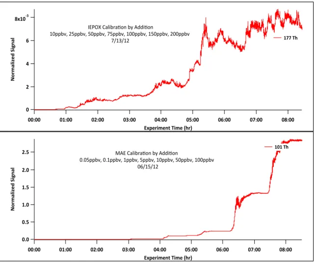
For use with the CIMS, the calibration by additions does have some
limitations. The first is that it is only applicable to the indoor smog chamber
under dark conditions. The second is that because the calibration uses the
chamber, a calibration and an experiment cannot be performed on the same day
since flushing required to clean the chamber prior to each experiment takes
about 22-24 hr. Although the CIMS is fairly stable from day-to-day, there are
some changes that could occur between the calibration and experiment. These
changes can be fluctuations in pressure, temperature, and reagent ion counts
just to name a few; however, they will be discussed in greater detail in a later
section. Finally, as highlighted by Figure 5, the calibration can be challenging if
the compound is not very stable as in the case of IEPOX. MAE’s calibration is
ideal since it is very stable in the gas phase, but this will not be true of every
compound. The actual calibration curves for MAE and IEPOX are represented in
Figure 6.
However, even under ideal cases it is essential that calibration be
performed frequently. In a series of experiments in which a calibration curve was
generated for MAE on three separate days the resulting slopes were almost
identical. Between each of these experiments the CIMS was completely
shutdown to account for tuning differences and the largest source of error
susceptible to human error. It should be noted though that these three
experiments were performed within six days of each other and as the calibrations
were applied to experiments at increasing intervals from the calibration date, the
accuracy of calculated MAE quantities appeared to deteriorate. For example,
injection of 25 ppbv MAE into the chamber two weeks after the calibration curve
was first generated gave a calculated value of 30 ppmv. Much of the discrepancy
associated with the MAE yield measurements is associated with this calibration
technique. It should be noted that the slopes from the calibration curves were
within 4% of each other and the R2 values were 0.997 or greater. Although there
appears to be a strong consistency of the calibration between these three
different days of calibration, they were all performed within the same week, and
thus, we are not able to conclude or expect that this consistency in calibration will
hold for longer periods of time (i.e., several weeks to months). All signals were
also normalized to the acetate ion (m/z 59) to take into account small fluctuations
in signal due to slight changes in pressure during the course of the experiment.
For non-ideal compounds, such as IEPOX, it is also very hard to obtain
over any length of time a stable signal to average for a calibration point or apply
a calibration to. It becomes up to the discretion of the user as to what part of the
epoxide injection the calibration is applied to and over what time frame the
gas-phase signal is averaged.
2.2.3 In-Line Aerosol Filter Experiments
Due to IMR clogging during seeded aerosol + epoxide experiments, more
16
without and then with a Pall PTFE filter between the chamber and the IMR so
that the gaseous epoxides had to pass through the filter and filter holder before
entering the IMR. These experiments were performed on a clean chamber.
Figure 7 shows the resulting time traces of both MAE and IEPOX. After the filter
is added to the CIMS sampling line, a 50% reduction is seen in the gas-phase
signal after reaching equilibrium. It takes several minutes to several hours for the
IEPOX and MAE signal to reach equilibrium, respectively. This seems to
suggest that the gas-phase epoxides have to build up on the PTFE before a
stable signal is reached.
Although a filter would help to block larger particles from entering the IMR
region of the CIMS, the reduction in the gas-phase signal is too severe. There is
also concern that the filter would act as a medium to facilitate more gas-particle
partitioning and unwanted secondary reactions; however, this has not been
studied extensively. Other ideas for excluding particles during high loading
experiments include tightly coiled sampling lines and an impactor. Taken
together, including the filter, cleaning and changing out of filters, lines, and wiping
an impactor would be essential in reducing the amount of gas-particle partitioning
and secondary reactions that could occur on the surface of an impactor,
sampling line, filter, or in the IMR.
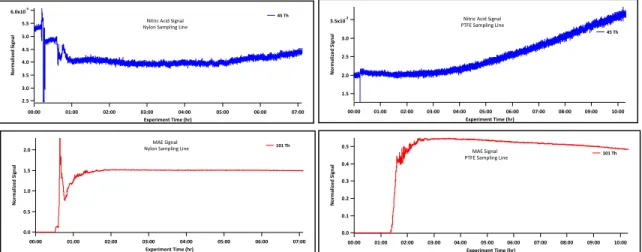
2.2.4 Sampling Line Material
As mentioned in the experimental section two different sampling line
materials were used. One sampling line was made of PTFE and then other nylon.
with each sampling line type connected to the chamber. This includes clean
chamber experiments, epoxide only experiments, and seeded experiments.
However, nylon is a known nitric acid scrubber (Spicer et al. 1976b), so the nitric
acid signal was compared in two different experiments, one with a nylon line and
the other with a PTFE line. In each of these experiments clean chamber air was
sampled for at least one hour and then a known amount of MAE introduced into
the chamber. Figure 8 shows a plot of the MAE and nitric acid signals (m/z 62)
during these experiments. Nitric acid appears to be more stable with a nylon
rather than a PTFE sampling line. It also appears that as MAE decreases the
nitric acid signal increases, suggesting that MAE is possibly reacting with
gaseous nitric acid. This observation was not explored in detail and needs more
clarification. Carefully controlled experiments should be performed before
drawing more conclusions on the use of sampling line material, as well as
conclusions about the reactivity of MAE and nitric acid. Suggested experiments
include injecting a known amount of nitric acid into the clean chamber and then
sampling with the different types of line material. Experiments in which the same
mixing ratio of MAE is used are also suggested so that they can be directly
compared to one another. It is important to note that a PTFE sampling line was
used in all MAE and IEPOX yield experiments since it is considered to be
non-reactive.
2.2.5 Epoxide with Subsequent Injection of Aerosol Experiments
When MAE was injected into a chamber pre-seeded with neutral
18
as observed for the gas-phase only experiment, since no particle growth was
observed on the SEMS instrument, consistent with previous work (Lin et al.,
2013). However, when MAE only experiments were compared with neutral seed
aerosol + MAE experiments, a distinct difference was observed between the
behavior of MAE signals. In the presence of neutral seed aerosol experiments
the MAE signal slowly decayed with time, consistent with behavior observed for
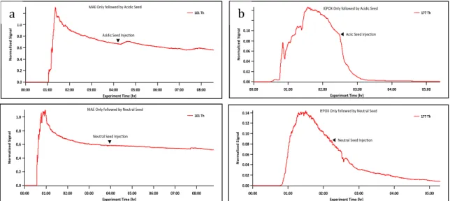
acidic seed aerosol + MAE experiments. In Figure 9 the decay of the CIMS
signal of MAE is plotted under both acidic and neutral seed conditions. As a
result of this observation, experiments were performed in which MAE or IEPOX
was injected into the chamber first and once stability was achieved, acidic or
neutral seed aerosol, , was introduced into the chamber. IEPOX was used as a
reference since its reaction rate with acidic seed is relatively fast compared to
neutral seed and its signal decays under both conditions. Figure 10a shows a
comparison of MAE (25 ppbv) with the addition of neutral seed and acidic and
Figure 10b a comparison of IEPOX (25 ppbv) with the addition of neutral and
acidic seed. IEPOX results shown here are consistent with prior CF3O- CIMS
used by Surratt et al. (2010). MAE data is not consistent with recent findings of
Lin et al. (2013). This suggests the possibility that the MAE signal was saturating
the detector and likely not allowing for an accurate interpretation of these
experiments. Further studies are needed in order to more directly compare with
the recent work of Lin et al. (2013). For example, instead of using 25 ppb MAE in
at 300 ppb MAE, but the chamber air should be diluted enough to allow MAE to
be detected within the linear dynamic range of the CIMS.
2.2.6 General Observations
Over the course of experiments it became obvious that the CIMS is a
sensitive instrument since it responds to a number of factors within and outside
of the experimental design. One of the most striking observations is that the
CIMS is extremely sensitive to pressure changes in the IMR. IMR pressure is a
large component of how the CI source works and dictates, to a large extent, the
type of chemistry that occurs in the IMR and what ions the instrument detects.
As shown by Figure 11, a slight change in IMR pressure (i.e., ~3 mbar)
drastically changes the signal that reaches the detector, and can mimic a
chemical reaction. As shown in this figure, a carboxylic acid standard (i.e.
malonic acid) was passed in front of the IMR to examine how the reagent ion
signal behaved when an organic acid was present. Then IMR pressure was
slowly adjusted to determine how sensitive the reagent ion signal was to
pressure changes. The result of a small pressure change is very similar to that
of a chemical reaction.
Changes in room temperature also affect the pressure of the IMR because
it changes the number of ions produced by the reagent ion system. For example,
a decrease in temperature will decrease the acetic acid vapor pressure, which in
turn reduces the pressure in the IMR (fewer molecules present). Thus reduction
20
CI can be a selective ionization technique and for this reason was
selected. Acetate reagent ion chemistry is selective towards ionizing gaseous
organic acids, especially compounds containing carboxylic acid functional groups.
This type of molecule may either be deprotonated by the acetate ion or form
clusters, allowing detection by the TOFMS. As expected, in comparing the
normalized signals from MAE and IEPOX experiments, it can be concluded that
not all molecules have similar response factors. For example 50 ppbv IEPOX will
only reduce the acetic acid signal by about 4% whereas the same mixing ratio of
MAE reduces the reagent ion signal by over 60%. It has been recommended at
the 2012 CIMS User’s Meeting that the reagent ion signal be reduced by more
than 15%.
When working with the CIMS, contamination in the reagent ion source is
of concern and should be carefully monitored. Figure 12 shows the difference in
the resulting mass spectra of a clean source versus a contaminated source.
Contamination was greatly reduced by continually bubbling nitrogen through the
reagent ion source, even when not in use. It was also determined that by
bubbling nitrogen continuously through the source, 250 mL of acetic anhydride
solution would last approximately one month.
Figure 12 also illustrates how clean the gas-phase background is in the
chamber. When the chamber is clean, selection of calibrant peaks may be
difficult as there are a limited number of peaks to choose from. In order to use a
specific peak as a calibrant, peak identity has to be known, peak shape needs to
acquired. The mass calibration also needs to be performed with reasonable
range of masses. This would include peaks at small masses, masses close to
the compound(s) of interest, and high masses. With the low background in a
clean chamber, it was often difficult to obtain a large mass range, as large
gas-phase compounds were not present on a consistent basis.
The CIMS signal was also variable on a day-to-day basis. This was
observed through the monitoring of the counts per second (cps) on the
acquisition software. As the acetic anhydride solution was consumed in the
reservoir bottle, the cps decreased. Additionally, replacement of the Po-210
source resulted in a dramatic increase in the CIMS signal and cps. During initial
operation of the CIMS, the reagent ion system was run continuously, but was
turned on mornings prior to CIMS operation. Monitoring of the acetate ion signal
at m/z 59 demonstrated that the reagent ion system required about 2-3 hours to
equilibrate before attaining a steady signal. This is shown in Figure 13. Due to
the long warm-up time and contamination issues, the reagent ion system was run
continuously. This helped to reduce the warm-up time to less than one hour,
which is also demonstrated in Figure 13.
The CIMS IMR had a tendency to clog at both the critical orifice from the
sample flow and at the critical orifice leading into the mass spectrometer.
Although the CIMS is a gas-phase instrument, sample flow contained both gas
and particles. However, for reasons discussed above no filter was placed
between the sample flow and the instrument unless specifically stated. Signs of
22
changes, and limited sample flow. Usually pressure fluctuations were observed
first, and thus, the instrument was cleaned immediately by venting and removing
the IMR and washing with MeOH to remove any particle build-up on the IMR
surface and at the critical orifices.
Each experiment that was performed with the CIMS was processed
separately to account for all the variables mentioned above since no two
experiments were identical. During processing, it was noted that peak shape
was always very similar from one experiment to the next suggesting that the MS
tuning was always consistent. It was also noted that the mass resolution of the
instrument was generally about 3000. If a bad mass calibration was performed a
lower resolution would result, however, since a post-experiment mass calibration
was always performed on the data sets this was generally not the case and in
some instances very good instrument resolution was obtained on the order of
4500.
2.3 CIMS Conclusions
Although calibration by addition is an alternative to the conventional
permeation tube system, any calibration is specific to the UNC indoor chamber
and a one-HC system. It is recommended that if this technique is to be further
used, a calibration be run before every experiment (in which quantification is
necessary) and is only done with compounds that are very stable in the gas
phase. It is further recommended that for the long term, either a permeation tube
system, or permeation tube-like system, be established for these epoxides. This
VOCs and their reaction products in the field and the calibration system used in
these studies is applicable.
In conclusion, the CIMS is a very powerful tool that will help the field move
forward in understanding gas-phase reactions and heterogeneous chemistry.
Although more development needs to be done to understand detection limits and
instrument variability, it will be a powerful tool for both chamber studies and
3. CALCULATION OF SOA YIELDS FROM REACTIVE UPTAKE OF IEPOX 3.1 IEPOX Experimental Set-up
Reactive uptake of β-IEPOX (see Figure 14 for structure) onto preexisting
seed aerosols was examined in the UNC 10-m3 flexible Teflon indoor chamber.
The detailed synthetic procedures for generating authentic IEPOX used in these
experiments are described in Zhang et al. (2012). Details of the indoor chamber
used in this study have been described previously by Lin et al. (2012). Briefly, a
SEMS equipped with a cylindrical-geometry differential mobility analyzer (DMA)
and a mixing condensation particle counter (MCPC) was used to measure
aerosol volume concentrations inside the chamber. The Aerodyne CIMS was
used to measure gas-phase organics. Prior to the start of each experiment, the
chamber was flushed with clean house air to replace at least five chamber
volumes. Chamber-background aerosol concentrations were monitored before all
the experiments to ensure no pre-existing aerosols were present. All chamber
experiments were performed at ~3% RH, with RH never exceeding 6%. Seed
aerosols at a concentration of 25-30 µg/m3 were introduced into the chamber by
atomizing 0.06 M MgSO4 + 0.06 M H2SO4 (aq) (Acidic Seed I) and 0.09 M
MgSO4 + 0.03 M H2SO4 (aq) (Acidic Seed II) seed aerosol solutions, respectively.
Precleaned microliter glass syringes were used to inject known amounts of
IEPOX into a 10 mL glass manifold. The manifold was wrapped with calibrated
chamber by flowing heated (~60°C) N2 (g) through the manifold at a flowrate of 3
L min-1 for at least 45 min. Gaseous IEPOX injections were determined to be
complete when the corresponding signal on the CIMS had stabilized (observed
as the [M + CH3COO]– ion at m/z 177). In all experiments, both the SEMS and
CIMS sampled continuously, and thus, it should be noted that particle nucleation
events did not occur during injection of the isoprene-derived epoxides. These
experiments were performed at four different concentrations of IEPOX for each
seed type. Concentrations of HC were: 10, 25, 50, and 75 ppbv. Control
gas-phase only experiments were also performed to monitor the behavior of IEPOX in
the chamber.
Gaseous IEPOX was quantified by using a calibration based on additions.
A small amount of IEPOX, 10 ppbv, was injected into the chamber and allowed to
stabilize for about 15 min. An additional 15 ppbv IEPOX was injected to give a
total of 25 ppbv IEPOX in the chamber and the resulting signal was then allowed
to stabilize in the same manner as the first injection. This process was repeated
so that the calibration points of 10, 25, 50, 75, 100, 150, and 200 ppbv IEPOX
were obtained. All signals were also normalized to the acetate ion (m/z 59) to
take into account small fluctuations in signal due to slight changes in pressure
during the course of each experiment.
3.2 IEPOX Results and Discussion
IEPOX yields were calculated and are summarized in Table 2.
The seed that was slightly less acidic (Acidic Seed II) did not yield any
26
ammonium sulfate seed. Particle growth with Acidic Seed I is also consistent
with previous work (Surratt et al. 2010; Lin et al., 2012). Interestingly, for
experiments using ≥ 50 ppbv of IEPOX, the SOA yield for Acidic Seed I drops off
significantly and is three times lower than the yield at 10 and 25 ppbv IEPOX.
This suggests that the seed aerosol can no longer accommodate additional
IEPOX from the gas phase under dry conditions (RH = 3%). Further work should
examine how higher RH conditions affect the ability of seed aerosol to uptake
IEPOX, as IEPOX is water soluble (Paulot et al., 2009).
It should also be noted that during the Acidic Seed II experiments, the
concentration of IEPOX calculated using the IEPOX calibration curve was higher
than the concentration initially injected. This has been discussed above in detail
in the CIMS gas-phase calibration results section and is likely due to
inconsistencies in signal of the CIMS on a day-to-day basis. A sample plot
showing the gas-phase and particle-phase data for both types of acidic seed
experiments is shown in Figure 15. The difference between reactivity of seed
aerosol acidity is demonstrated by the growth of particles with more acidic seed
present and no observable growth with the less acidic seed. It is also apparent
that less IEPOX was observed in the more acidic experiment (Acidic Seed I) than
the less acidic experiment (Acidic Seed II), indicating that IEPOX was taken up
onto seed aerosol from the gas phase.
High-resolution fitting was performed on the IEPOX cluster peak and
resulted in a high-resolution mass of 177.0768Da, which matches IEPOXs
gas-phase IEPOX was injected into the chamber during these experiments.
During more complex experiments and during fieldwork, it is expected that the fit
be not as close since the spectra collected will likely be more complex.
3.3 IEPOX Conclusions
IEPOX was determined to be detectable as a cluster ion with acetate
CIMS. Although the CIMS was tuned to strongly decluster ions, mixing ratios as
small as 10 ppbv of IEPOX were observed. If the CIMS had been tuned more
towards clustering, smaller mixing ratios of the IEPOX would likely have been
observed. When comparing the set of yield experiments, IEPOX was much more
reactive under more acidic conditions. Under conditions where the bulk solution
was 0.06 M H+ or less, IEPOX appeared to be non-reactive and behaved as if in
the presence of neutral ammonium sulfate seed conditions. The calculated SOA
yields are subject to a large degree of uncertainty due to the uncertainty in
gas-phase calibration and instrument variability. Based on these results it is expected
that IEPOX-derived SOA will be present in areas with low-NO and high aerosol
acidity versus areas that do not meet these criteria. The reaction between
gaseous IEPOX and pre-existing aerosol is also expected to be rapid and implies
that the reactivity is high and therefore its relative lifetime in the atmosphere
could be short compared to that of MAE. However, this lifetime will depend on
the accommodation coefficients of pre-existing atmospheric aerosols, which will
likely be variable due to RH (and therefore aerosol liquid water content), aerosol
composition, acidity, phase, and aerosol concentrations. Aside from gas-phase
28
equilibrium partitioning approach to calculate the amount of gas-particle
4. CALCULATION OF SOA YIELDS FROM REACTIVE UPTAKE OF MAE 4.1 MAE Experimental Set-up
Similarly to the IEPOX experiments, reactive uptake of MAE (see Figure
16 for structure) onto preexisting seed aerosols was examined in the UNC 10-m3
flexible Teflon indoor chamber using the Aerodyne CIMS. Detailed synthetic
procedures used in generating MAE required for these experiments have been
described recently by Lin et al. (2013). A SEMS was also used to measure
aerosol volume concentrations during this set of chamber experiments. As with
the IEPOX experiments, both the SEMS and CIMS sampled continuously during
each experiment so that continuous particle- and gas-phase data were collected
and all chamber experiments were performed at ~3% RH, with RH never
exceeding 6%.
Prior to the start of each experiment, the chamber was flushed with clean
house air for over 24 h to replace at least five chamber volumes.
Chamber-background aerosol concentrations were monitored before all the experiments to
ensure no pre-existing aerosols were present. Acidic and neutral sulfate seed
aerosols were introduced into the chamber by atomizing 0.06 M MgSO4 + 0.06 M
H2SO4 (aq) and 0.06 M (NH4)2SO4 (aq) seed aerosol solutions, respectively.
30
chamber by flowing heated (~60°C) N2 (g) through the manifold at a flowrate of 3
L min-1 for at least 30 min. Gaseous MAE injections were determined to be
complete when the corresponding signal on the CIMS had stabilized (observed
as the [M – H]– ion at m/z 101). It should be noted that SEMS measurements
indicated that no particle nucleation events occurred during the injection of
gaseous MAE into the smog chamber. Control gas-phase only experiments were
also performed to monitor the behavior of the gaseous species inside the
chamber.
Gaseous MAE was quantified by using a calibration based on additions. A
small amount of MAE, 0.05 ppbv, was injected into the chamber and allowed to
stabilize for about 30 min. An additional 0.05 ppbv MAE was injected to give a
total of 0.1 ppbv MAE in the chamber and this signal was allowed to stabilize in
the same manner as before. This process was repeated so that the calibration
points 0.05, 0.1, 1, 5, 10, 50, and 100 ppbv MAE were obtained (note, the CIMS,
as configured, is much more sensitive to MAE than IEPOX). The calibration was
performed three different times to compare the reproducibility of the CIMS signal
on different days.
4.2 MAE Results and Discussion
MAE yields were calculated and are summarized in Table 3. As noted in
the experimental section, all MAE experiments were conducted with 25 ppbv
MAE. From the table it can easily be seen that the results of this study were
inconsistent. SOA yields were unable to be calculated in almost all experiments
likely results in very large uncertainties with the small particle growth detected by
the SEMS. During the experiments the acetate ion signal on the CIMS
decreased by ~ 50%, and at times was smaller than the MAE signal, which
indicates that acetate was being titrated by MAE in the IMR and was no longer in
excess. This has been covered in detail in the CIMS gas-phase calibration
results section, but does imply that the CI source was no longer operating as it
should. Figure 17 shows a representative time series of both acidic and neutral
seed aerosol experiments with the addition of 25 ppbv MAE.
High-resolution fitting was performed on the MAE single ion peak and
resulted in a high-resolution mass of 101.0244Da, which matches MAEs
molecular mass exactly. It was expected that this fit match very well since only
gas-phase MAE was injected into the chamber during these experiments. During
more complex experiments and during fieldwork, it is expected that the fit be not
as close since the spectra collected will likely be more complex.
In both the acidic and neutral seed experiments no observable particle
growth was seen, making yield calculations impossible to perform. This differs
with recent results reported by Lin et al. (2013), in which the uptake was
measured at much higher epoxide concentrations. At the lower mixing ratios in
the experiments described here, observable uptake using the SEMS instrument
is too small to detect. Also observed in Figure 17, MAE appears to decline in
concentration when exposed to a seeded chamber. This observation raises the
question as to whether this change is occurring in the smog chamber or as a side
32
MAE was injected into the chamber first and then followed by seed aerosol
injection were performed. However, the results of those experiments did not
help to clarify the reaction mechanism of MAE and the details remain unclear.
4.3 MAE Conclusions
The proposed intermediate MAE was found to be an extremely stable
compound in the gas phase of the smog chamber, although no conclusions could
be drawn on SOA yields. However, based on the data collected, MAE has
slower kinetics than IEPOX, which may result in particle growth being too small
to observe, even though both MAE and IEPOX are isoprene derived. Moreover,
the experiments must be repeated at lower concentrations of MAE in order to
prevent a significant titration of acetate ions. As a result of acetate titration the CI
source was not operating with acetate in excess, which is essential when using
CI, to reduce side reactions as well as to stay within the linear dynamic range of
the CIMS. With compounds like MAE that efficiently ionize in the CI source,
dilution sources or detuning of the CIMS will be required if high mixing ratio
chamber experiments are desired. In addition, more work is needed to examine
the reactivity of MAE under different chamber conditions and develop more
effective approaches to calibrating this compound in the gas phase. In future, it
is important that MAE can be detected at low concentrations with a unique mass
spectral signature so it can be observed during field studies. Future CIMS work
should examine whether this compound can be observed from the
whether it can be observed during field studies where concentrations are
expected to be low.
In order to calculate SOA yields from the reactive uptake, these
experiments need to be repeated at higher MAE mixing ratios, calibrating more
frequently, and either diluting the gas-phase sample into the CIMS or detuning
the CIMS. This additional work is required in order to obtain better yield
estimates. Another approach such as measuring the reactive uptake coefficients
(or reaction probabilities, γ) to determine the heterogeneous removal rate of MAE,
could also be explored. It is likely that the heterogeneous removal rate will be
highly variable, depending on particle composition, phase, acidity, presence of
surfactants, and liquid water content. Once the heterogeneous removal rate has
been determined, the current modeling framework can be refined to represent
5. FUTURE WORK AND ATMOSPHERIC IMPLICATIONS
In moving forward with this work, an alternative way to estimate yields and
compound reactivity should be sought after and explored. With this instrument
flow tube studies, as used in Bertram et al. (2009), may be easier and more
efficient in estimating accommodation coefficients (reaction probabilities). These
experiments could be explored with different seed aerosols and under different
conditions, such as higher RH. These experiments can be less time-consuming
than smog chamber experiments, so it is possible to explore many reactions or
conditions in a given amount of time.
Future work is also needed in determining what other small organic acids
can be detected with the CIMS. This is especially important in utilizing this
instrument in field studies. The more information that is known about which
species can be detected and the limits of detection, the more powerful this
instrument becomes in helping to elucidate some of the complex chemistry in our
atmosphere that leads to SOA formation.
As with detecting more organic acids using acetate-CI, it will also be
beneficial to use different reagent ion chemistries with the CIMS. Other
chemistries such as I-, CF3O-, and H3O+, will also be very important in helping to
elucidate complex atmospheric reaction pathways since each of these is
selective towards different compound classes. The use of different CI
the field continues to grow. New groups could elect to use a different reagent ion
and explore its reaction possibilities and characterize a CIMS instrument
according to that particular chemistry and set of conditions. The implication of
this collaborative approach is a much deeper understanding of atmospheric
gaseous species we have not been able to adequately detect and measure in the
past, resulting in significant advancements of our understanding of SOA
formation. This likely could bring SOA model predictions closer to ambient
36
TABLES
Table 1. Operational voltages and settings for TOF
Location Setting Location Setting Location Setting
IMR 0 Reference 36.08 U/0low 46
Nozzel 2.33 Ion0Lens/2 135 U/0high 680
Q1/Entr./Pl. 7.5 Defl./Flange 36.48 Lens 1800
Q1/Front 15.93 Deflector 39.61 Drift 3000
Q1/Back 014.07 RF/Ampl./1 0.3 Refl./Grid 652.5
Lens/Skimmer 013.25 RF1 2810000Hz Refl./Backplane 700
Skimmer 06.76 RF/Ampl./2 2.9 Hardmirror 0
Q2/Front 5.0 RF2 4100000Hz Post/Acc. 2700
Q2/Back 5.9 U/+low 700 MCP* 2060
Skimmer/2 15.5 U/+high 30
TOF.Power.Supply.Operation.Voltages.and.Settings
All#units#in#volts#unless#noted#differently *voltage#varied#depending#on#tuning
Table 2. IEPOX yield results. The amount of new particle mass formed (ΔMo) was divided by the
HC reacted (ΔROG) which was converted to µg/m3 and an assumed aerosol density of 1.25.
IEPOX SOA Yield
Seed Type [HC] Date Yield (%)
Acidic Seed I 10ppbv 7/16/12 6.137
Acidic Seed I 25ppbv 7/20/12 6.233
Acidic Seed I 50ppbv 7/21/12 2.988
Acidic Seed I 75ppbv 7/25/12 2.178
Acidic Seed II 10ppbv 8/10/12 I.S.
Acidic Seed II 25ppbv 8/21/12 I.S.
Acidic Seed II 50ppbv 8/23/12 I.S.
Acidic Seed II 75ppbv 8/28/12 I.S.
*I.S. indicates that there was an insignificant amount of particle growth observed and a yield could therefore not be calculated and is assumed to be zero.
Table 3. MAE yield results. The amount of new particle mass formed (ΔMo) was divided by the
HC reacted (ΔROG) which was converted to µg/m3 and an assumed aerosol density of 1.25. For
the majority of these experiments a yield could not be determined due to the ΔMo being to small
and below the limit of detection on the SEMS.
MAE SOA Yield
Seed Type Date Yield (%) Δ Mo (µg/m3) Δ ROG (µg/m3)
Acidic Seed 6/29/12 9.8 2.11 21.60
Acidic Seed 8/14/12 I.S. 0.65 0.72
Acidic Seed 10/11/12 I.S. 1.49 1.59
Neutral Seed 8/3/12 I.S. 0.53 0.18
Neutral Seed 10/9/12 I.S. 1.83 3.9
Neutral Seed 10/23/12 I.S. 1.47 0.8
38
FIGURES
Fig. 1. Low-NO regime isoprene reaction mechanism (Surratt et al., 2010)
Fig. 2. High-NO regime isoprene reaction mechanism (Lin et al., 2013)
Fig. 3. Aerodyne CIMS schematic
40
Fig. 4. CIMS time traces for gaseous MAE and gaseous IEPOX. MAE only experiment was with 300ppbv gaseous MAE and IEPOX only experiment was with 300ppbv gaseous IEPOX. Traces show difference in stability of compound in the chamber and mass spectrometer.
2.0
1.5
1.0
0.5
0.0
Nor
m
aliz
ed0Signal
00:00 01:00 02:00 03:00 04:00 05:00 06:00 07:00
Experiment0Time0(hr)
01010Th MAE$Only$Experiment
$MAE$Injec3on
0.12
0.10
0.08
0.06
0.04
0.02
0.00
Nor
m
aliz
ed2Signal
00:00 01:00 02:00 03:00 04:00 05:00 06:00 07:00
Experiment2TIme2(hr)
21772Th IEPOX&Only&Experiment
Fig. 5. IEPOX and MAE calibration by addition time traces. Large differences between IEPOX and MAE arise in signal stability and instrument sensitivity.
2.5
2.0
1.5
1.0
0.5
0.0
Nor
m
aliz
ed0Signal
00:00 01:00 02:00 03:00 04:00 05:00 06:00 07:00 08:00
Experiment0Time0(hr)
01010Th !!!!!!!!!!!!!!!!!!!!!!!!!!!!!MAE!Calibra+on!by!Addi+on
0.05ppbv,!0.1ppbv,!1ppbv,!5ppbv,!10ppbv,!50ppbv,!100ppbv !!!!!!!!!!!!!!!!!!!!!!!!!!!!!!!!!!!!!!!!!!!!!!!06/15/12
8x10%3
6
4
2
0
Nor
m
aliz
ed4Signal
00:00 01:00 02:00 03:00 04:00 05:00 06:00 07:00 08:00
Experiment4Time4(hr)
41774Th
!!!!!!!!!!!!!!!!!!!!!!!!!!!!!!!IEPOX!Calibra-on!by!Addi-on
42 y"="0.0266x" R²"="0.99663" y"="0.0277x" R²"="0.99874" y"="0.0278x" R²"="0.99857" 0" 0.5" 1" 1.5" 2" 2.5" 3"
0" 20" 40" 60" 80" 100" 120"
N o rm al ize d Si g n al Concentration (ppb)
MAE Calibration Comparisons
6/11/12" 6/13/12" 6/15/12" Linear"(6/11/12)" Linear"(6/13/12)" Linear"(6/15/12)" y"="0.00003877x" R²"="0.98173" 0" 0.001" 0.002" 0.003" 0.004" 0.005" 0.006" 0.007" 0.008" 0.009"
0" 20" 40" 60" 80" 100" 120" 140" 160" 180" 200"
N o rm al ize d Si g n al
Concentration (ppbv)!
IEPOX Calibration Curve
07/13/12"" Linear"(07/13/12")"
Fig. 6. MAE and IEPOX calibration curves. Curves were generated by averaging gaseous signal at each calibration point. All CIMS signals have been normalized and background corrected.
Fig. 7. Gaseous MAE and IEPOX time traces without and with a PTFE filter. MAE and IEPOX were injected into the chamber at 15 and 50ppbv, respectively.
Fig. 8. Nitric acid (m/z 62) and corresponding MAE time traces for nylon and PTFE sampling lines.
MAE concentration in the experiments with the nylon line and PTFE line were 300ppbv and 25ppbv, respectively. 0.5 0.4 0.3 0.2 0.1 0.0 Nor m aliz ed2Signal
02:00 03:00 04:00 05:00 06:00
Experiment2Time2(hr) 21012Th !!!MAE!Only!(No!Filter!vs.!Filter) ! !!!!!!!! without!filter !!!!! with!filter 0.14 0.12 0.10 0.08 0.06 0.04 0.02 0.00 Nor m aliz ed2Signal
01:15 01:30 01:45 02:00 02:15 02:30
Experiment2Time2(hr) 21772Th IEPOX&Only&(No&Filter&vs.&Filter)& &&&&&&& without&filter with&filter &&&& 6.0x10&3 5.5 5.0 4.5 4.0 3.5 3.0 2.5 Nor m aliz ed5Signal
00:00 01:00 02:00 03:00 04:00 05:00 06:00 07:00
Experiment5Time5(hr) 5455Th !!!Nitric!Acid!Signal Nylon!Sampling!Line 2.0 1.5 1.0 0.5 0.0 Nor m aliz ed0Signal
00:00 01:00 02:00 03:00 04:00 05:00 06:00 07:00
Experiment0Time0(hr) 01010Th !!!!!!!MAE!Signal Nylon!Sampling!Line 0.5 0.4 0.3 0.2 0.1 0.0 Nor m aliz ed2Signal
00:00 01:00 02:00 03:00 04:00 05:00 06:00 07:00 08:00 09:00 10:00
Experiment2Time2(hr) 21012Th !!!!!!MAE!Signal PTFE!Sampling!Line 3.5x10'3 3.0 2.5 2.0 1.5 Nor m aliz ed3Signal
00:00 01:00 02:00 03:00 04:00 05:00 06:00 07:00 08:00 09:00 10:00 Experiment3Time3(hr)
3453Th
44
Fig. 9.( a) Acidic Seed + 25ppbv MAE and (b) Neutral Seed + 25ppbv MAE experiment time traces. Both time traces show MAE loss although MAE is expected only under acidic conditions.
Fig. 10. (a) 25 ppbv MAE and (b) 25 ppbv IEPOX only experiments followed by the addition of acidic or neutral seed. MAE data is inconclusive and a difference in reaction of MAE between acidic and neutral seed could not be determined. IEPOX shows a distinct difference in the loss of IEPOX between acidic and neutral seed, as expected.
0.8 0.6 0.4 0.2 0.0 Nor m aliz ed1Signal
00:00 01:00 02:00 03:00 04:00 05:00 06:00
Experiment1Time1(hr) 11011Th Acidic%Seed%=%25ppb%MAE 0.8 0.6 0.4 0.2 0.0 Nor m aliz ed1Signal
00:00 01:00 02:00 03:00 04:00 05:00 06:00 07:00 08:00
Experiment1Time1(hr) 11011Th Neutral(Seed(+(25ppb(MAE 1.2 1.0 0.8 0.6 0.4 0.2 0.0 Nor m aliz ed2Signal
00:00 01:00 02:00 03:00 04:00 05:00 06:00 07:00 08:00 Experiment2Time2(hr) 21012Th Acidic%Seed%Injec+on %%%%%%%%%%%%%% MAE%Only%followed%by%Acidic%Seed% 1.0 0.8 0.6 0.4 0.2 0.0 Nor m aliz ed2Signal
00:00 01:00 02:00 03:00 04:00 05:00 06:00 07:00 08:00 Experiment2Time2(hr) 21012Th Neutral(Seed(Injec/on ((((((((((((((( MAE(Only(followed(by(Neutral(Seed 0.14 0.12 0.10 0.08 0.06 0.04 0.02 0.00 Nor m aliz ed2Signal
00:00 01:00 02:00 03:00 04:00 05:00 Experiment2Time2(hr) 21772Th IEPOX&Only&followed&by&Acidic&Seed Aciic&Seed&Injec5on 0.14 0.12 0.10 0.08 0.06 0.04 0.02 0.00 Nor m aliz ed2Signal
00:00 01:00 02:00 03:00 04:00 05:00
Experiment2Time2(hr)
21772Th
IEPOX&Only&followed&by&Neutral&Seed
Neutral&Seed&Injec8on
a
b