surface quality of Ti-15333 alloy in CT and UAT
R. Muhammad
a,1,*, N. Ahmed
a, S. Maqsood
b, K. Alam
c, M.U. Rehman
a, and
V.V. Silberschmidt
da. Department of Mechanical Engineering, CECOS University of IT & Emerging Sciences, Peshawar, KPK, Pakistan. b. Faculty of Industrial Engineering, UET Peshawar Jalozai Campus, Pakistan.
c. Department of Mechanical and Industrial Engineering, Sultan Qaboos University, Musqat, Oman.
d. Wolfson School of Mechanical, Electrical and Manufacturing Engineering, Loughborough University, Loughborough, Leicestershire LE11 3TU, UK.
Received 1 May 2017; received in revised form 10 January 2018; accepted 7 July 2018
KEYWORDS Tool wear; Surface roughness; Machining; Cutting forces; Temperature in process zone; Ti-alloys.
Abstract. Ultrasonically Assisted Turning (UAT) is a progressive machining method in which vibration is applied to the cutting insert in the direction of the cutting tool velocity to reduce the cutting forces signicantly and increase the surface nish noticeably. However, the key question about the tool damage caused by the vibration and its eect on the cutting forces, surface roughness, and process zone temperature is still unknown in UAT. This paper conducts an experimental analysis of the eect of a worn tool in UAT and Conventional-Turning (CT) of -Ti-15V-3Al-3Cr-3Sn (Ti-15333) alloy on the surface quality of a machined surface, temperature of the process zone, and cutting forces using KC5510 (PVD TiAlN) and CP500 (PVD (Ti,Al)N-TiN) cutting inserts. In UAT, the tool edge damages in CP500 inserts increased with tested machining time, which resulted in the growth of 8 N and 10 N in tangential force component in CT and UAT, respectively. Similarly, with the progression of tool edge damage, growth rates of 1.7% and 9.3% in the process zone temperature were observed in CT and UAT, respectively. The surface roughness results revealed a gradual degradation with machining time; however, the results of UAT with a worn tool were signicantly better than those of CT with a virgin tool. © 2019 Sharif University of Technology. All rights reserved.
1. Introduction
In recent decades, machining of the alloys has always been a subject of interest in the power-generation, chemical, aerospace, and biomedical industries, which has been mainly focused on nickel and
titanium-1. Present address: Department of Mechanical Engineering, University of Bahrain, P.O. Box 32038, Bahrain. *. Corresponding author.
E-mail addresses: [email protected], and [email protected] (R. Muhammad). doi: 10.24200/sci.2018.20692
based alloys [1]. The mediocre machinability of Ti alloys using conventional-machining-processes is the main disadvantage due to its high strength and lower thermal conductivity. The high level of cutting forces and concentrated temperature at the tool-workpiece interaction zone resulting in diminutive tool life and, hence, poor quality nish of machined components.
With considerable advances in technology, new advanced alloys such as Ti15Zr12Nb and Ti6Al2Sn 4Zr6Mo have been introduced on the basis of strength and resistance to corrosion. However, the main prob-lem associated with those materials is its machin-ability with conventional machining processes. The
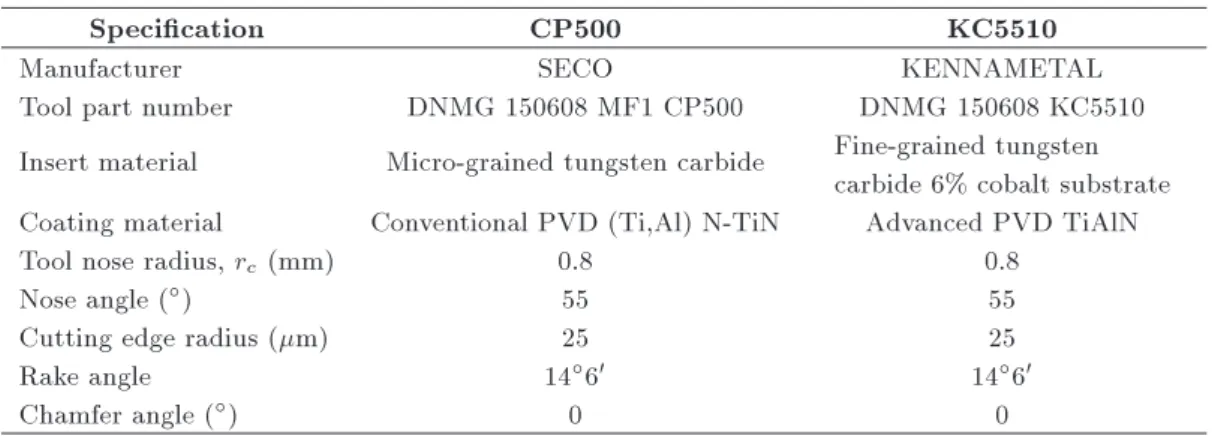
Table 1. Specications of cutting inserts.
Specication CP500 KC5510
Manufacturer SECO KENNAMETAL
Tool part number DNMG 150608 MF1 CP500 DNMG 150608 KC5510 Insert material Micro-grained tungsten carbide Fine-grained tungsten
carbide 6% cobalt substrate Coating material Conventional PVD (Ti,Al) N-TiN Advanced PVD TiAlN
Tool nose radius, rc(mm) 0.8 0.8
Nose angle () 55 55
Cutting edge radius (m) 25 25
Rake angle 1460 1460
Chamfer angle () 0 0
high contact pressure and process zone temperature result in short tool life and poor surface quality [2-5]. Numerous eorts have been made to enhance the machining of these hard-to-cut alloys using advanced coating techniques used in cutting inserts [2,3,6], new tool materials [7], conventional/cryogenic coolants [8-11], assisted/hybrid machining processes [12-14], and internal processes, e.g., alloy modication without signicant changes in material properties [15,16].
Among many, Ultrasonically Assisted Turning (UAT) is one of the developed processes that has shown signicant improvement in the machining of hard-to-cut alloys [15,17-28]. UAT transforms a continuous cutting process into a transient one by the superim-position of ultrasonic-vibration on the cutting insert, resulting in an intermittent contact between them and a machined workpiece. This technique has shown a 50% improvement in surface quality and a 65% decline in cutting forces in the machining of Ti and nickel-based alloys. Most recently, Muhammad et al. [14,29-31] introduced a new variant of UAT called Hot Ultrasonically Aanassisted Turning (HUAT), which has shown an added decline in cutting forces and improvement in surface quality. However, no attempt has been made to examine the inuence of tool life in either UAT and in HUAT on nished product quality. Therefore, in the current work, an experimental procedure was adopted to study the inuence of tool edge condition on resulted cutting forces, average pro-cess zone temperature, and surface quality of machined components using two types of cutting inserts (CP500 and KC5510) as recommended by the tool suppliers for the conventional turning regimes of -Ti-15V-3Al-3Cr-3Sn (Ti-15333).
2. Experimental procedures
2.1. Cutting inserts and workpiece material A 50-mm bar of -Ti alloy (-Ti-15V-3Al-3Cr-3Sn designated as Ti-15333) with a length of 300 mm was used in CT and UAT tests. Additional details about
the studied alloy can be found elsewhere [15,19]. CP500 and KC5510 cutting inserts recommended by the manufacturer for Ti alloys were used in experiments. CP500 cutting inserts are suitable for intermittent cutting, whereas KC5510 is an advanced micro-grain coating insert consisting of 6% cobalt of substrate material and is recommended for moderate cutting of hard-to-cut materials. The specications of these inserts are presented in Table 1.
2.2. Machining
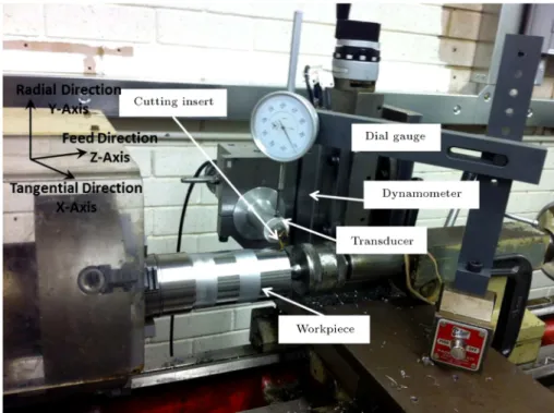
A universal 300 Harrison lathe machine was used for CT and UAT of Ti15333 alloy. The tool post of the lathe machine was reformed to support a piezoelectric transducer to impose vibrations (20 kHz of frequency and 10 m of amplitude) on the cutting insert, as shown in Figure 1. The ultrasonic system developed at Loughborough University, UK is an open-loop system and is optimized for the above ultrasonic parameters. The maximum force reduction and improvement in surface nish are reported for Ti- and Ni-based al-loys [17,18,22,32]. A four-jaw chuck was used to clamp the workpiece on the lathe machine. A mechanical dial gauge was used to adjust the eccentricity of the workpiece material. The following cutting conditions were employed in this investigation:
Cutting speeds (m/min): 10 and 30;
Feed rate (mm/rev): 0.1;
Depth-of-cut (mm): 0.3;
Dry cutting;
Time interval, t (s): 100, 300, 500, and 700. All experiments were conducted four times to achieve realistic statistics for the experimentally achieved data. A Kistler dynamo-meter was used to capture cutting forces in real time. The output signal from the dynamo-meter passed through an amplier followed by a picoscope to get a digital format of all cutting forces. Later on, a Matlab program was used to calculate the average cutting forces for all tests.
Figure 1. Setup used for CT and UAT experimentation.
Figure 2. (a) Special insert xture. (b) Cutting insert placed on oriented plane of xture.
For thermal measurements, an FLIR Therma-CAMTMSC3000 system was used for real-time
acquisi-tion. The new stirling-cooled Quantum Well-Infrared-Photon (QWIP) enables the FLIR ThermaCAMTM
system to image the process at lower noise exposure and better image uniformity using the continuous recording mode. Further details of the system can be found in the experiment elsewhere [14].
The surface roughness analysis of machined spec-imens was carried out using Mitutoyu-Surftest-211 equipment. A standard calibrated block available with the instrument was used to calibrate the system before considering surface roughness reading in experiments. The standard, arithmetic mean surface-roughness pa-rameter (Ra) was calculated. The Ra measurements were taken at dierent locations of the specimens at specied time intervals as mentioned above, and each test was repeated at least four times to achieve good statistical data for Ra.
Similarly, a 3D optical measurement system, innite-focus by Alicona, was used for tool wear anal-ysis. A special tool xture was designed to ensure accurate positioning of the cutting insert in various stages of its life in experimentation (Figure 2(a)). The orientation of the plane of the xture (Figure 2(b)) was achieved through a series of trials, carried out on the Alicona innite-focus system to get a good-quality scan of the inserts. A 5 objective of the system was used because of its larger eld of view compared to a 10 objective, and it was found that it was fully capable to cope with the wear-prone region even when the wear progress occurred along the ank face of the insert. A step-wise procedure was used to carry out tool wear analysis in both CT and UAT. Initially, the inserts were used to perform CT and UAT on the Ti-15333 for selected time intervals. An ultrasonic bath was given to the inserts after machining to remove unwanted solid, semi-solid or liquid contaminants, which can include
metallic and non-metallic debris, chips, dirt particles, and other elements from the surface of the insert. A cleaning procedure with pressurized air was used to ensure removal of any dirt particles to achieve a more accurate scan of the cutting insert.
The Alicona machine software enjoys an in-built feature known as dierence measurement, which is dedicated to volume measurement. This feature was used to calculate the amount of volume reduction for the cutting inserts after machining by comparing a scan of the virgin sample (a reference scan) with that of the used insert. All experiments for UAT and CT were conducted on the in-house state-of-the-art exper-imental setup available at Loughborough University, UK. Additional details about the experimental setup can be found elsewhere [15,19]. The experiments were repeated three times for each cutting condition. For CP500, the spread of data was huge because one insert, each at both cutting speeds, does not fail due to BUE formation. However, the rest of the data are reasonably in good shape and the results are repeatable in both CT and UAT.
3. Results and discussions 3.1. Tool wear
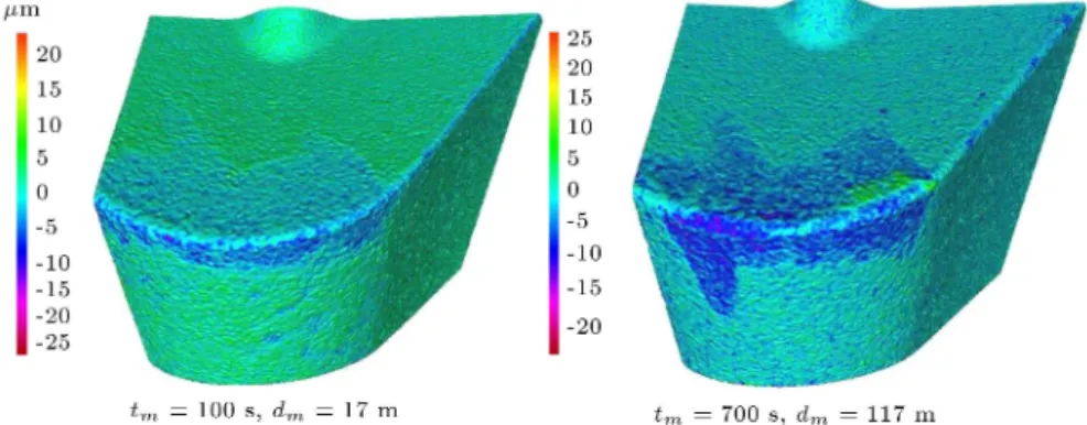
The tool wear analysis was carried out using Innite-Focus by Alicona. A reduction in volume at the cutting edge was achieved in both CT and UAT at the tested cutting parameters, as shown in Figures 3 and 4. A volume reduction of 1:6 106 m3 in CP500 inserts
was calculated in CT at 100 s. The inserts experienced a high level of cutting forces, and process zone temper-ature after making initial contact with the workpiece materials resulted in a rapid reduction in the volume of the insert cutting edge. The progress in volume reduction was amplied with an increase in machining time, and a further reduction of 0:15 106 m3 in
volume of the cutting edge was observed at 300 s. Similarly, a total reduction of 1:9106m3in tool edge
Figure 3. Volume reduction in cutting inserts at various time intervals in CT.
Figure 4. Material removal progress in CT in KC5510 insert [35].
volume was measured after 700 s of machining of Ti-15333. A better performance was shown by the CP500 inserts in CT at 30 m/min. An average reduction of 1:5 106 m3 and 1:8 106 m3 in tool edge volume
was observed at 100 s and 300 s, respectively, when compared to the virgin insert. The progression in tool damage continued with machining time, and average reductions of 1:9 106 m3 and 2:1 106 m3 were
calculated at 500 s and 700 s, respectively. The level of volume reduction at a tested time interval in CP500 inserts at 10 m/min and 30 m/min was almost the same with some minor variation (see Figure 5).
Similarly, the performance of KC5510 cutting inserts was also evaluated at the studied cutting param-eters. An average volume reduction of 1:8 106 m3
and 1:6106m3at 100 s was calculated at 10 m/min
and 30 m/min cutting speeds, respectively. An increase in volume reduction was observed with machining time, and the average decrease of 2:5 106 m3, 2:6
106 m3, and 2:7 106 m3 was measured at 300 s,
500 s, and 700 s, respectively, at 10 m/min. On the other hand, at 30 m/min, a reduction in volume of 2:2 106 m3, 2:4 106m3, and 2:5 106 m3 was
calculated at 300 s, 500 s, and 700 s, respectively. The CP500 and KC5510 inserts are designed for CT that have shown better performance at both cutting speeds. However, the volume removed at both cutting speeds in CP500 cutting inserts was lower than that in KC5510 cutting inserts (see Figure 3). The level of tool edge volume lost by CP500 inserts at the tested cutting speeds was approximately the same with some minor uctuations. On the contrary, in KC5510 cutting inserts, the material removal rate was reduced with an increase in cutting speeds from 10 m/min to 30 m/min. The substrate material of these inserts contained small contents of Cobalt particles, providing them with a tougher and ner grain structure suitable for high-load applications.
Transition to vibro-impact machining in the UAT regime aected the character of tool life in terms of
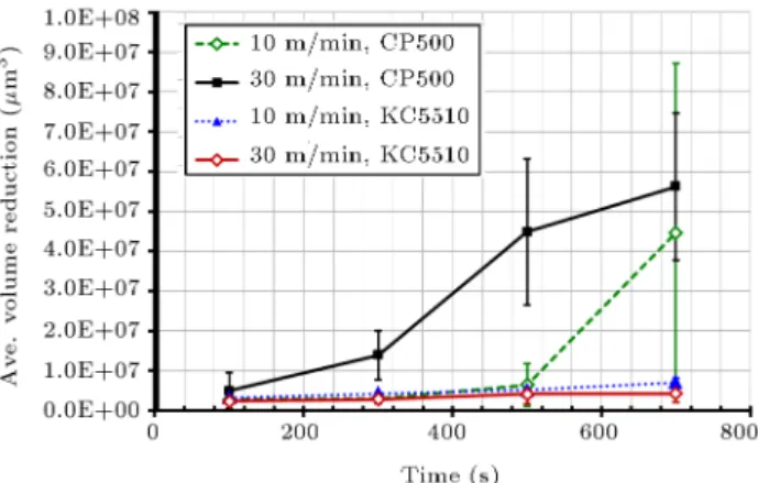
Figure 5. Volume reduction in cutting inserts at various time intervals in UAT.
Figure 6. Material removal progress to catastrophic failure in CP500 cutting insert in UAT at a cutting speed of 10 m/min in various stages [35].
volume reduction. The decay in average volume of tested cutting inserts in UAT is shown in Figure 4. The levels of volume reduction for both cutting inserts in UAT were comparatively higher than those in CT. At 100 s, the level of volume lost by the CP500 insert was 2:7 106 m3. The volume reduction increased
with an increase in time, and average reduction rates of 3:0 106 m3, 6:4 106 m3, and 44:5 106 m3
were observed at 300 s, 500 s, and 700 s, respectively. The rapid failure of the CP500 inserts observed at 700 s resulted in a rapid increase of volume reduction by a factor of 6. The decay in volume of one of the tested CP500 inserts is shown in Figure 6. At 30 m/min,
CP500 inserts showed better performance up to 100 s, and a reduction of 4:9 106 m3 in cutting edge
volume was calculated. However, a rapid increase in volume reduction was observed for the subsequent time internals. Reduction rates of 13:8 106 m3, 44:8
106 m3, and 56:2 106 m3 was calculated at 300 s,
500 s, and 700 s, respectively. The catastrophic failure in CP500 insert in the form of plastic deformation was linked to the substrate composition of CP500 insert, causing signicantly lower impact resistance [33].
A reduction of 3:2 106 m3 in KC5510 volume
was observed at 100 s in UAT at a cutting speed of 10 m/min. With an increase in machining time, further
Figure 7. Material removal progress of insert KC5510 in UAT at a cutting speed of 10 m/min in various stages [35].
increases of nearly 1:0 106 m3, 0:8 106 m3, and
1:9 106 m3were reported at 300 s, 500 s, and 700 s,
respectively. Similarly, these inserts demonstrated even better performance at 30 m/min in UAT. Initially, a reduction of 2:3 106 m3 in tool edge volume
was calculated at 100 s. However, the decay in tool edge volume increased with an increase in time, and the total decreases of 2:8 106 m3, 4:1 106 m3,
and 4:2 106 m3 were calculated at 300 s, 500 s,
and 700 s, respectively. This extremely positive tool-wear behavior of KC5510 insert in UAT, as compared to that of CP500, can be explained by its substrate composition [33]. The material removal development in the KC5510 cutting insert is presented in Figure 7.
Based on a comparison of the material removal progress in the two studied inserts in CT and UAT, a shorter tool life for CP500 inserts was observed in UAT when compared to KC5510. Although the coating was eventually removed in both inserts, the substrate of insert KC5510 demonstrated signicantly greater resistance to localized plastic deformation and to failure once the physical damage began, showing better performance in UAT [33,34].
3.2. Cutting forces
The results obtained from experimentation at 10 m/min demonstrated that a substantial drop of approximately 75% was achieved in Ft in UAT, as
shown in Figures 8 and 9. Similarly, a considerable decline of approximately 70% in Fr was also recorded
using both inserts. The superposition of vibrations on
Figure 8. The average level of Ftand Fr observed in
UAT and CT of Ti-15333 using CP500 cutting inserts and V = 10 m/min.
the cutting insert induces separation of the cutting tool from the chip in one complete vibration cycle, leading to a reduction in average force levels [18]. The tool comes into contact with the chip in the penetration stage, which is the reason why an almost peak level of the cutting forces was observed in CT, where the level of forces started to decline and reached the zero level during the retraction stage. As a result, a substantial drop in average Ft and Fr was observed
in UAT.
The level of Ft for both cutting inserts was
Figure 9. The average level of Ft and Fr observed in
UAT and CT of Ti-15333 using KC5510 cutting inserts and V = 10 m/min.
Figure 10. The level of Ft and Fr observed in UAT and
CT of Ti-15333 using CP500 cutting inserts and V = 30 m/min.
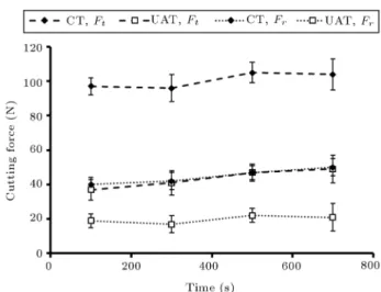
both cutting speeds. In CT, Ft of 98 N and 102 N
was observed at 10 m/min using CP500 and KC5510 inserts, respectively. Similarly, Frof 46 N and 44 N was
observed in CP500 and KC5510, respectively. Minor uctuations in Ftand Frwere observed in both inserts
with an increase in the machining time. The inuence of cutting speed on Ftand Fr was negligible for both
inserts in CT, whereas a gradual growth in the level of Ftand Frwas observed in UAT with an increase in the
cutting speed from 10 m/min to 30 m/min, as shown in Figures 10 and 11. The level of Ft increased from
25 N to 39 N and from 29 N to 37 N using CP500 and KC5510 inserts, respectively. Similarly, a growth of 4 N and 6 N was calculated in Fr for CP500 and KC5510
inserts, respectively. This observation was expected because, in UAT, the separation of the cutting tool reduced with an increase in cutting speed, resulting in
Figure 11. The level of Ft and Fr observed in UAT and
CT of Ti-15333 using KC5510 cutting inserts and V = 30 m/min.
an increase in the level of Ftand Frwhen compared to
those obtained at 10 m/min [17-19]. A minor variation (up to a maximum of 12 N) in the level of Ft and Fr
was observed with progression of tool edge damage for both inserts in UAT and CT; however, the eect of tool edge damage was not severe in the level of Ftand Frin
UAT. Hence, the level of Ftand Frobserved in UAT for
both cutting inserts was considerably lower than that observed in CT, besides its poorly short tool life. This demonstrates the importance and signicance of UAT in machining high-strength alloys with worn tools. 3.3. Process zone temperature
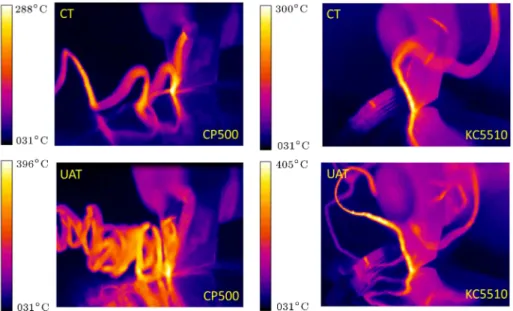
The average process zone temperature in both UAT and CT was also examined experimentally for both inserts, as presented in Figure 12. The calculated temperature levels did not show the actual temperature generated in the tool workpiece interaction region due to the obstacle generated by the chip during process zone temperature recording. Similarly, the problems are associated with aligning the camera at a preferable angle due to the restrictions produced by the machine. Still, the data obtained in the current study presented a good quantitative analysis of UAT and CT in turning of Ti-15333 using CP500 and KC5510 cutting inserts.
The prime cause of heat generated during machin-ing processes is the plastic deformation in the primary and secondary zones of deformation with a minimal contribution of frictional eect (below 10%) [36]. The experimental results indicate that the average process zone temperatures in CP500 and KC5510 cutting inserts in UAT were higher than those observed in CT. The possible reason is the amount of energy applied to the tool in the form of vibrations, which increased the relative cutting velocity of the inserts in UAT [22].
The measured process zone temperatures in CT at 10 m/min using CP500 and KC5510 inserts were 288C
Figure 12. Process zone temperature in UAT and CT for both tools at 100 s and V = 10 m/min.
Figure 13. Process zone temperature in UAT and CT at various time intervals using CP500 inserts.
and 300C, respectively. In addition, the superposition
of vibration on the cutting insert yielded an additional growth of approximately 100C in UAT (see Figures
13 and 14). The levels of process zone temperatures measured in CP500 and KC5510 inserts were 396C
and 405C, respectively. Furthermore, a noticeable
growth in the average process zone temperature was noticed for both inserts with a rise in cutting speed, as expected. The average growth rates of 113C and
125C were observed in CT using CP500 and KC5510
inserts, respectively, when cutting speed increased from 10 m/min to 30 m/min. Similarly, an average increase in the process zone temperature of 109C and
116C was measured in UAT using CP500 and KC5510
inserts, respectively.
Figure 14. Process zone temperature in UAT and CT at various time intervals using KC5510 inserts.
The cutting edge condition has a marginal inu-ence on the average process zone temperature in the machining of Ti-alloys; in the current study, an increase in the average process zone temperature was noticed with the tool damage progression. In CT, the rise of average process zone temperature was minor for both tools due to lower damage to the insert edge. In CP500 inserts and 10 m/min, a growth of 5C was measured
at 700 s when compared to the level of temperature observed at 100 s. Similarly, a growth of 20C was
achieved at 700 s in KC5510 inserts. At 30 m/min, the level of process zone temperature increased from 401C to 410C in CP500 inserts, whereas, in KCC5510
inserts, an increase of 6C was obtained.
On the contrary, a visible increase in the average process zone temperature was detected in UAT with
Surface roughness Ra (m) Ra (m) Ra (m) Ra (m) CT 1.82 0.61 1.61 0.31 1.79 0.42 1.95 0.52 UAT 0.96 0.32 1.15 0.29 1.35 0.31 1.47 0.26
CP500 cutting insert, V = 30V = 30V = 30 m/min
Time 100 s 300 s 500 s 700 s
Surface roughness Ra (m) Ra (m) Ra (m) Ra (m) CT 1.09 0.41 1.00 0.32 1.16 0.39 1.31 0.22 UAT 0.82 0.24 0.91 0.39 0.99 0.23 1.19 0.36
KC5510 cutting insert, V = 30V = 30V = 30 m/min
Time 100 s 300 s 500 s 700 s
Surface roughness Ra (m) Ra (m) Ra (m) Ra (m) CT 1.02 0.33 1.13 0.25 1.25 0.29 1.39 0.19 UAT 0.73 0.25 0.93 0.39 0.85 0.35 1.01 0.51
the tool damage progression. In CP500 cutting insert, the total growth of 68C was observed at cutting
speeds of 700 s and 10 m/min when compared to those obtained at 100 s, whereas, in KC5510, a growth of 42C was noticed at 700 s. Similarly, at a cutting speed
of 30 m/min, the total rise in temperature at 700 s in CP500 and KC5510 cutting inserts was 44C and 27C,
respectively, compared to those obtained at 100 s. One of the main disadvantages of the UAT with the studied alloy is the high process zone temperature; however, the rise of average process zone temperature further reduced the yield strength of materials and made it easy for the cutting insert to remove the excessive amount of material with no signicant eect on the machined specimen [14,19].
Based on the achieved experimental results, as the machining time increased from 100 s to 700 s, the growth of the process zone temperature in UAT was higher than that in CT for both of the inserts, leading to its poor life. However, the 6% cobalt content in the substrate of KC5510 cutting insert increased its toughness, leading to higher tool life in UAT when compared to CP500 cutting inserts.
3.4. Surface roughness
Surface quality is measured to be one of the vibrant factors in metal work as it is related directly to fatigue
life of most structures [37]. Therefore, the surface topology analysis was carried out for the machined surface using CP500 and KC5510 in both CT and UAT at the studied time intervals. The level of Ra observed in CT for CP500 insert was 1.73 m, whereas the level of Ra at 30 m/min was 1.09 m. A signicant improvement of 36% in Ra was achieved with an increase in the cutting speed from 10 m/min to 30 m/min. Similarly, the levels of Ra observed at 10 m/min and 30 m/min in KC5510 inserts were 1.82 m and 1.02 m, respectively.
Further, a momentous decline in Ra was noticed in UAT for both inserts, compared to that obtained in CT (see Table 2). The level of Ra declined from 1.73 m to 1.01 m in CP500 inserts at a cutting speed of 10 m/min. Similarly, 24% improvement in surface roughness was achieved in UAT at a cutting speed of 30 m/min. Furthermore, the superposition of vibration in cutting direction on KC5510 inserts resulted in improvements of 48% and 28% in surface quality at 10 m/min and 30 m/min, respectively. However, the dierence in Ra levels was found minimal in CP500 and KC5510 cutting inserts due to their similar geometries in both CT and UAT; however, KC5510 inserts comparatively produced better surface nish than CP500 inserts. Degradation in surface quality was observed in CT and UAT for both tools
with an increase in machining time, as expected [35]. The level of Ra at a cutting speed of 10 m/min in CT increased from 1.73 m to 1.75 m at 300 s and, then, reduced slightly to a level of 1.74 m at 500 s. Finally, the level of Ra reached 1.80 m at 700 s. Similarly, the levels of Ra observed for KC5510 inserts at 300 s, 500 s, and 700 s were 1.61 m, 1.79 m, and 1.95 m, respectively. In this regard, 16% degradation in surface quality at a cutting speed of 30 m/min was achieved in CP500 inserts at 700 s when compared to the results obtained at 100 s. Similarly, a 26% increase in Ra level was measured in KC5510 inserts at 700 s. The quality of surface nished achieved in CP500 inserts was better than that in CT when compared to the surface nish obtained using KC5510 inserts. The prime reason for better surface quality of CP500 inserts in CT is its acceptable performance and better tool life in comparison to KC5510 inserts.
Similarly, 39% and 34% degradation rates of sur-face quality in CP500 and KC5510 inserts, respectively, were measured in UAT at 700 s at a cutting speed of 10 m/min when compared to the surface nish achieved at 100 s. In addition, an increase of 31% and 27% in Ra level was observed in CP500 and KC5510 insert at 30 m/min, respectively.
Based on a comparison of the results listed in Table 2, a signicant improvement in surface quality was achieved in UAT when compared to CT in dierent stages of experimentations for both inserts. The im-provement of surface roughness was noticeable; besides, the tool life was found poor in UAT for both cutting inserts since they were designed for CT processes.
In a nutshell, the tool life for KC5510 cutting insert was comparatively higher in UAT than that in CP500 inserts, hence better surface nish in UAT in various cutting conditions. Moreover, the level of surface nish obtained in UAT for CP500 cutting inserts was prominently better, compared to the results obtained in CT.
4. Conclusions
The main conclusions of this work are:
A substantial reduction of 70% in cutting forces was observed in UAT, compared to that in CT at lower cutting speeds;
A great benecial eect of vibrations on the ma-chined surface was observed by achieving better surface quality in UAT. The measured level of Ra was still lower than 1.6 m in UAT at 700 s;
The KC5510 cutting inserts yielded comparatively better surface nish in UAT than CP500 due to their enhanced tool life;
The level of cutting forces observed in UAT with a
worn tool was signicantly lower than that of forces observed in CT;
The process zone temperature in UAT for both tools was approximately 34% higher than that in CT at lower cutting speeds;
Both inserts demonstrated poor insert life in UAT of Ti-15333 when compared to their performance in CT in the tested cutting conditions. However, based on the comparative analysis of both inserts and surface quality achieved in the tests, KC5510 is recommended for UAT of Ti-15333.
References
1. Peters, M. and Leyens, C., Titanium and Titanium Alloys, Wiley-VCH; Germany (2002).
2. Ucun, I., Aslantas, K., and Bedir, F. \An experimental investigation of the eect of coating material on tool wear in micro milling of Inconel 718 super alloy", Wear, 300(1-2), pp. 8-19 (2013).
3. Avila, R.F., Mancosu, R.D., Machado, A.R., Vecchio,
S.D., da Silva, R.B., and Vieira, J.M. \Comparative analysis of wear on PVD TiN and (Ti1-x Alx)N coatings in machining process", Wear, 302(1-2), pp. 1192-1200 (2013).
4. Ezugwu, E., Da Silva, R.B., Bonney, J., and Machado, A.R. \Evaluation of the performance of CBN tools when turning Ti-6Al-4V alloy with high pressure coolant supplies", Int. J. of Mach. Tools and Manuf., 45, pp. 1009-1014 (2005).
5. Ozel, T. \Computational modelling of 3D turning: Inuence of edge micro-geometry on forces, stresses, friction and tool wear in PcBN tooling", J. of Mater. Proc. Tech., 209, pp. 5167-5177 (2009).
6. Mkaddem, A., Soussia, A.B., and Mansori, M.E. \Wear resistance of CVD and PVD multilayer coatings when dry cutting ber reinforced polymers (FRP)", Wear, 302(1-2), pp. 946-954 (2013).
7. M'Saoubi, R., Johansson, M.P., and Andersson, J.M., \Wear mechanisms of PVD-coated PCBN cutting tools", Wear, 302(1-2), pp. 1219-1229 (2013).
8. Dhar, N.R., Kishore, S.V.N., Paul, S., and Chattopad-hyay, A.B., \The eects of cryogenic cooling on chips and cutting forces in turning AISI 1040 and AISI 4320 steel", J. of Eng. Manuf., 216-part B, pp. 713-724 (2002).
9. Bermingham, M.J., Kirsch, J., Sun, S., Palanisamy, S., and Dargusch, M.S., \New observations on tool life, cutting forces and chip morphology in cryogenic machining Ti-6Al-4V", Int. J. of Mach. Tools and Manuf, 51(6), pp. 500-511 (2011).
10. Dhananchezian, M. and Kumar, P.M. \Cryogenic turn-ing of the Ti-6Al-4V alloy with modied cuttturn-ing tool inserts", Cryogenics, 51, pp. 34-40 (2011).
and Manuf, 50(2), pp. 174-182 (2010).
14. Muhammad, R., Maurotto, A., Demiral, M., Roy, A., and Silberschmidt, V.V. \Thermally enhanced ultrasonically assisted machining of Ti alloy", CIRP J. of Manuf. Sci. and Tech, 7(2), pp. 159-167 (2014).
15. Muhammad, R., Hussain, M.S., Maurotto, A., Siemers, C., Roy, A., and Silberschmidt, V.V. \Anal-ysis of a free machining + titanium alloy using conventional and ultrasonically assisted turning", J. of Mater. Proc. Tech, 214(4), pp. 906-915 (2014).
16. Maurotto, A., Siemers, C., Muhammad, R., Roy, A., and Silberschmidt, V.V. \Ti alloy with enhanced machinability in UAT turning", Metall. and Mater. Trans. A, 45(6), pp. 2768-2775 (2014).
17. Muhammad, R., Roy, A., and Silberschmidt, V.V. \Finite element modelling of conventional and hybrid oblique turning processes of titanium alloy", Proc. CIRP, 8, pp. 509-514 (2013).
18. Muhammad, R., Demiral, M., Roy, A., and Silber-schmidt, V.V. \Modelling the dynamic behaviour of hard-to-cut alloys under conditions of vibro-impact cutting", J. of Phy.: Conf. Ser., 451, pp. 1-11 (2013).
19. Maurotto, A., Muhammad, R., Roy, A., and Sil-berschmidt, V.V. \Enhanced ultrasonically assisted turning of a -Titanium alloy", Ultrasonics, 53(7), pp. 1242-1250 (2013).
20. Nategh, M.J., Razavi, H., and Abdullah, A. \An-alytical modeling and experimental investigation of ultrasonic-vibration assisted oblique turning, part I: Kinematics analysis", Int. J. of Mech. Sci., 63(1), pp. 1-11 (2012).
21. Muhammad, R., Maurotto, A., Roy, A., and Silber-schmidt, V.V. \Ultrasonically assisted turning of Ti-6Al-2Sn-4Zr-6Mo", J. of Phy.: Conf. Ser., 382, pp. 1-12 (2012).
22. Muhammad, R., Ahmed, N., Roy, A., and Silber-schmidt, V.V. \Turning of advanced alloys with vi-brating cutting tool", Solid State Phenom., 188, pp. 277-284 (2012).
23. Muhammad, R., Ahmed, N., Roy, A., and Silber-schmidt, V.V. \Numerical modelling of vibration-assisted turning of Ti-15333", Proc. CIRP, 1, pp. 347-352 (2012).
27. Kumabe, J., Fuchizawa, K., Soutome, T., and Nishi-moto, Y. \Ultrasonic superposition vibration cutting of ceramics", Prec. Eng., 11(2) pp. 71-77 (1989).
28. Ahmed, N., Mitrofanov, A.V., Babitsky, V.I., and Silberschmidt, V.V. \Stresses in ultrasonically assisted turning", App. Mech. and Mater., 5, pp. 351-358 (2006).
29. Muhammad, R., Maurotto, A., Roy, A., and Silber-schmidt, V.V. \Hot ultrasonically assisted turning of -Ti alloy", Proc. CIRP, 1, pp. 336-341 (2012).
30. Muhammad, R., Maurotto, A., Roy, A., and Silber-schmidt, V.V. \Analysis of forces in vibro-impact and hot vibro-impact turning of advanced alloys", App. Mech. and Mater., 70, pp. 315-320 (2011).
31. Muhammad, R., Ahmed, N., Ullah, H., Roy, A., and Silberschmidt, V.V. \Hybrid machining process: Ex-perimental and numerical analysis of hot ultrasonically assisted turning", Int. J. Adv. Manuf. Tech., 97, pp. 2173-2192 (2018).
32. Muhammad, R., Ahmed, N. Ullah, H., and Silber-schmidt, V.V. \Dynamic behaviour of -Ti-15333 in ultrasonically assisted turning: Experimental and nu-merical analysis", Scientia Iranica, Transac. B: Mech. Engg, 24(6), pp. 2904-2914 (2017).
33. Exner, H.E. and Gurland, J.A. \A review of pa-rameters inuencing some mechanical properties of tungsten carbide cobalt alloys", Powd. Metall., 13, pp. 13-31 (1970).
34. Mills, B. and Redford, A.H. Machinability of Engi-neering Materials, London; New York, Applied Science Publishers (1983).
35. Muhammad, R, Mistry, A, Khan, S. W, Ahmed, N., Roy, A., and Silberschmidt, V. V., \Analysis of tool wear in ultrasonically assisted turning of -Ti-15V-3Al-3Cr-3Sn alloy" Scientia Iranica, Transac. B: Mech. Engg., 23(4), pp. 1800-1810 (2016).
36. Komanduri, R. and Hou, Z.B. \On thermoplastic shear instability in the machining of a titanium alloy (Ti-6Al-4V)", Metall. and Mater. Trans. A, 33(9), pp. 2995-3010 (2002).
37. Ulutan, D. and Ozel, T. \Machining induced surface integrity in titanium and nickel alloys: A review", Int. J. of Mach. Tools and Manuf, 51(3), pp. 250-280 (2011).
Biographies
Riaz Muhammad graduated in Mechanical Engineer-ing with distinction from UET Peshawar, Pakistan, in 2006 followed by his MS and PhD degrees in Mechan-ical Engineering from Ghulam Ishaq Khan Institute of Science and Technology (GIKI) and Loughborough University in 2009 and 2013, respectively. He is currently working as an Assistant Professor in Mechan-ical Engineering Department, University of Bahrain, Bahrain. His research activities include nite element modelling, hybrid machining process, industry 4.0, product design and development, composite, polymers and biomedical materials.
Naseer Ahmed received BS and MS degrees in Me-chanical Engineering from UET Peshawar and GIKI, respectively. He received his PhD degree form Lough-borough University, UK in 2007. He is Professor of Manufacturing at CECOS University, Pakistan, heads mechanics of advanced materials and manufacturing research group (AM2RG) and Director of research and development. His research activities include, manufac-turing, biomedical materials, composite materials and assisted machining processes.
Shahid Maqsood is currently working as an Associate Professor in the Industrial Engineering Department, UET Peshawar, Jalozai Campus, Pakistan. He received his BSc degree in Mechanical Engineering from UET Peshawar and his MS degree in in the same eld from Ghulam Ishaq Khan Institute of Engineering Sciences and Technology, Topi, Swabi, Pakistan in 2003. His research expertise are in the eld of manufacturing processes, machining, industrial process optimization, and stochastic analysis.
Khurshid Alam is Assistant Professor in the Depart-ment of Mechanical and Industrial Engineering, Sultan Qaboos University, Sultanate of Oman. He received his
PhD degree in Mechanical Engineering from Wolfson School of Mechanical and Manufacturing Engineering, Loughborough University, UK, his BEng degree in the same eld from University of Engineering and Technol-ogy, Peshawar, Pakistan, and his MSc degree in Design and Manufacturing from GIK Institute of Engineering Sciences and Technology, Topi, Pakistan. His current research is focused on the experimental measurements and computational analysis of bone cutting forces in conventional and vibrational mode. His other areas of research are experimental and computational mod-eling and analysis of biomechanical components and systems.
Muftooh Ur Rehman received his BSc degree in Mechanical Engineering from UET Peshawar, his MS degree in Mechanical Engineering from GIKI, Pakistan in 2010, his PhD degree from University of Strathclyde, United Kingdom, in 2016 in incremental sheet forming of advanced alloys. His research interest includes dig-ital manufacturing, sustainable manufacturing, indus-try 4.0, industrial robotics, product development, man-ufacturing, material testing and management through modelling and simulation, design and analysis (FEA and CFD), and experimental validation.
Vadim V. Silberschmidt educated at Perm Techni-cal University (USSR). He heads the Mechanics of Ad-vanced Materials Research Group with 30+ members. He is a Charted Engineer, Fellow of the Institution of Mechanical Engineering and Institute of Physics. He is Editor-in-Chief of Mechanics of Advanced Materials and Modern Processes, Associate Editor of Journal of Engineering Materials and Technology. His research activities include multi-scale models of damage and fracture evolution in microstructured materials, nite-element analysis of complex deformational behaviour, damage and fracture of advanced materials under various loading conditions, impact fatigue, mechanics of composites and nano-composites, Mechanics.
![Figure 7. Material removal progress of insert KC5510 in UAT at a cutting speed of 10 m/min in various stages [35].](https://thumb-us.123doks.com/thumbv2/123dok_us/8367115.2222199/6.892.153.724.153.541/figure-material-removal-progress-insert-cutting-various-stages.webp)