Plasmonic Solar Cells, a New Way to Enhance Energy
Conversion Efficiency: Analysis and Modeling of
Effect of Metal Geometry
Farshad Farhadnia*, Ali Rostami, and Samieh Matloub
Faculty of Electrical and Computer Engineering, University of Tabriz, Tabriz , Iran
*Corresponding author Email:
[email protected]
Received: Jun. 13, 2018, Revised: Apr. 8, 2018, Accepted: May. 5, 2018, Available Online: June. 30, 2019 DOI: 10.29252/ijop.13.1.61
ABSTRACT— In this article, the effect of
plasmonic properties of metal nanoparticles with different shapes, and moreover, their plasmonic-photonic interaction, on solar cell performance were investigated and simulated. Because of low conversion efficiency and then high cost of solar cells, it is difficult to commercialize and replace them with conventional energy resources. But in recent years, the plasmonic solar cell has been very popular. In this study, it is shown that the enhancement of near-field electromagnetic waves severely affects the generation rate, which handles the carrier’s generation in the solar cell equations and causes alteration of the photocurrent. This means that by manipulating the plasmonic properties of nanoparticles (shape and density) and their interaction with photons in solar cell structure, distribution of electromagnetic fields will be altered. Hence, the optical power related to the poynting vector is changed. So, with the aim of improving the solar cell some important parameters such as alteration of nanoparticle shape and their inter-distance were investigated. Finally, a comparison between traditional solar cells and our improved structure was undertaken.
K
EYWORDS:
Plasmonic,
Nanoparticles,
Plasmonic-photonic interaction, Solar cell
I.
INTRODUCTION
Photovoltaic (PV) technology, which involves
the direct conversion of sunlight into electric
energy, is one of the components of an
evolving energy mix. Several attractive
features of this technology include
pollution-free operation, relatively low costs and
modularity. In the future, solar cells may well
play an increasingly prominent role in global
electricity generation in order to limit
environmental pollution and to slow down the
rise of greenhouse gas concentration [1-5]. As
a simple model, a semiconductor solar cell is
based on a simple p-n junction. A qualitative
description of cell performance can be given in
terms of a simple model based on the Shockley
diode equation in the dark and under
illumination. This model is sufficient for
understanding the basic carrier transport
mechanisms in the cell, and roughly for
predicting the performance parameters of a
solar cell. Most of the traditional solar cells are
based on silicon because of its stability,
non-toxicity,
well-developed
technology
and
abundance in nature. However, a major
limitation of the thin-film solar cells is poor
absorption of light, compared to the
wafer-based solar cells [6-10]. It is well established
that light-trapping by increasing its optical
path length inside the absorbing film, for
obtaining high efficiency, is crucial for
thin-film solar cells. In light of the above
restriction, a new method using plasmonic
structures can improve the absorption of light,
due to excitation of localized surface plasmon.
Noble metals such as silver (Ag), gold (Au),
aluminium (Al) and copper (Cu), support
surface plasmon due to their free-electron-like
behavior. Surface plasmon is the collective
oscillations of excited free electrons of
metallic particles. This unique property of
metallic nanoparticles (NPs) can be used to
enhance the optical absorption of solar cells
through scattering of light and near-field
concentration
of
light
[11-17].
The
contribution of these mechanisms depends on
the nanoparticle material, shape, and size, and
the refractive index of the surrounding
dielectric. In this work, we used the
plasmonic-based
NPs
to
enhance
the
traditional solar cell specification. It is shown
that the near-field electromagnetic wave
severely affects generation rate, which handles
the carrier generation in the solar cell
equations. This means that by manipulation of
plasmonic properties of the NPs in the solar
cells
structure,
the
distribution
of
electromagnetic fields can be altered. Hence,
the optical power and generation rate related to
the Poynting vector is changed, which can
influence directly solar cell output parameters.
So, for improving the solar cell critical
parameters, the alteration of NPs shapes and
inter-distance
were
done.
Finally,
the
comparison between traditional solar cell and
our improved structure was performed. Finally
it should be noted that all of the simulations in
this work were done by COMSOL 4.4 and
MATLAB.
II.
BACKGROUND AND THEORY
A few equations describe the behavior of
charge carriers in semiconductors under the
influence of an electromagnetic field; all of
which
cause
deviations
from
thermal
equilibrium conditions. These equations are
called the basic equations for semiconductor
device. The Poisson equation relates the static
electric field to the space-charge density [2-4]:
2 2
0 s
d x d x x
dx dx
(1)
where
φ,
ε
0, and
ε
sare the electrostatic
potential, the permittivity of free space and the
static relative permittivity of the medium,
respectively. Based on our study, the electron
current density (J
e) and the hole current
density (J
h) are given by [2]:
e e e
dn x
J x qD q n x x
dx
(2)
h h h
dp x
J x qD q p x x
dx
(3)
where
n, p, μ
e, μ
h,
D
e, and D
hare electron and
hole densities, the electron and hole mobility,
and the electron and hole diffusion constants,
respectively. It is notable that the first terms on
the right hand side of Eqs. 2 and 3 are
diffusion currents driven by a concentration
gradient, and the second terms are drift
currents driven by the electric field. Indeed,
the latter case will be manipulated by
nanoparticles’ (NPs) or nanorods’ (NRs)
Plasmonic radiation. It means that by the use
of NPs/NRs, electromagnetic distribution in
the different sections of p-n junction will be
altered, so the drift currents driven by the
electric field. Indeed, the latter case will be
manipulated
by
nanoparticles’
(NPs)
Plasmonic field. It means that by the use of
NPs, electromagnetic distribution in the
different sections of
p-n junction will be
altered, so the drift currents driven by the
electric field can be changed. Also, by
changing the NPs’ materials, shape, geometry
and inter-distance between them, the electric
field distribution can be easily manipulated. In
the following formula, divergence of the
current
density,
J,
is
contributed
to
recombination and generation rates of charge
carriers by the continuity equation. Electron
and hole continuity equations may be written
as [2]:
1
0
e e edJ
x
r x
G x
q
dx
(4)
1 0 h h h dJ xr x G x q dx
(5)
In these equations
r(x) and
G(x) are the
position-dependent volume recombination and
photo-generation rates, respectively. Finally,
by substituting Eqs. 2 and 3 into the continuity
Eqs. 4 and 5, a couple set of transport
equations are driven as [2]:
2
2 0
e e e e e
d n dn d
D n r x G x
dx dx dx
(6)
2
2 0
h h h h h
d d d
D r x G x
dx dx dx
(7)
Electron and hole transport equations, Eqs. 6
and 7, are coupled with the electric field E.
The coupled set of differential equations can
be solved with different degrees of accuracy. It
is important to note that for improving the
solar cells’ specification, in this work we used
NPs Plasmonic properties, which influence the
original electric field in near-field state. In
other words, the original field in the solar cell
structure can be perturbed by NPs Plasmonic
in near-field. For extra and effective
manipulation, an array of NPs was used. It is
known that because of the interaction between
NPs Plasmonics, non-uniform electromagnetic
fields are arisen in solar cell’s different areas,
which contribute to optical power and optical
generation rate. Actually, optical generation
rate as an important parameter in the solar cell
system, contributes to the time averaged
Poynting vector, which is given by [6]:
ave opt opt
S
G
h
(8)
where,
opt, Save, ћ, and v are optical quantum
yield, time averaged Poynting vector, Planck
constant
and
incidence
frequency,
respectively. The time averaged Poynting
vector has been considered as the radiant flux
around any NPs and calculated by E×H*. The
optical generation rate in Eq. 8 can be
substituted in Eqs. 4 and 5 and electron and
hole continuity equations can be re-written by
this alteration. Indeed, by manipulating optical
generation rate in Eq. 8, the solar cell’s key
parameters such as
photon current can be changed. The traditional solar cell photon current can be illustrated as [18, 19]:( ) ,
ph phs i c r in pl ref
G
I I k T T G G G
G
(9)
where Iphs, ki, Tc, and Tr are solar cell current under standard condition, temperature coefficient of short circuit current, solar cell operating temperature and reference temperature, respectively. Moreover, G
and Gref attribute to the intensity of irradiance in
solar cell and reference intensity, about 103
Watts/m2, respectively. As a result of that G
includes the incidence irradiance (Gin) as well as intensity generated by the NPs near-field Plasmonic field (GPl). It should be noted that after calculating solar cell photo-current, the solar cell open circuit voltage and short circuit current can be obtained, which are given by [18, 19]:
0 ph c oc I AKT V Ln q I
(10)
where A, K, and q are the diode ideality factor, Boltzmann’s constant and electron charge, respectively. Moreover, I0 relates to the current dependency on temperature and short circuit current. This means that by manipulating Poynting vector in the Plasmonic condition, solar cell’s key parameters such as optical generation rate and solar cell photon current are remarkably changed. For this, in this study, we investigated the NPs optical properties’ manipulating effect on generation rate and optical power, and Poynting vector was considered as the critical factor for this study. At last, the solar cell’s I-V (current-voltage) relations, which depend on Iph and its original factors such as NPs Plasmonic field intensity, are introduced by: 0 0 ph c s
I I I
AKT
V Ln IR
q I
(11)
0exp 1
s s
ph
c sh
q V IR V IR
I I I
AKT R
(12)
In these equations, Rs and Rsh are the solar cell series and shunt resistors, respectively. Therefore, with knowledge about this point, the NPs Plasmonic field intensity has effectively influenced the photon current and solar cell output voltage and current; we can design a solar cell based on NPs for engineering the solar cell photon current.
III.
RESULTS AND DISCUSSION
In this section, the simulation results in the case of the 2-D simple structure solar cell are illustrated. Based on Eqs. 8-13, which emphasize the plasmonic effect of optical power and optical generation rate on solar cell photon current and its influence on output current and voltage, we can compare four different structures with traditional structures.
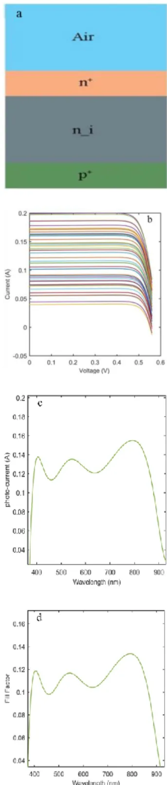
Fig. 1. a) Traditional solar cell structure; b) I-V curve; c) Photo-current, d) fill factor vs wavelength
Actually, the original aim was to manipulate the photon current based on optical power and optical generation rate engineering, which can dramatically affect solar cell fill factor and its other important parameters. In fact, by manipulating the NPs’ optical properties, we can try to alter the solar cell fill factor.
Figure 1a shows the traditional simple p-n
structure without any NPs. In terms of this case, the interaction of light with different wavelengths was simulated by COMSOL; its results are illustrated in Figs. 1(b), (c), and (d). In these figures we show the I-V curve, photo-current, and fill factor versus different wavelengths, respectively. In Fig. 1(b), this shows the I-V curve for different wavelengths, in which the maximum current for the traditional structure is about 0.2 A. We tried to improve this case by manipulating the plasmonic-photonic interaction. The photo-current alteration versus wavelength is illustrated in Fig. 1(c); its average is about 0.12 A. Finally, the solar cell fill factor for traditional structure is shown in Fig. 1(d).
It is easily seen that its change is based on photo-current alteration. The alteration of parameters relates to the interaction of light with the solar cell at different wavelengths. We can manipulate the penetration of light into the solar cell structure to change light intensity for extra manipulation of the solar cell photo-current based on equation 9. In other words, in this equation we can manage the intensity radiation with regard to the plasmonic feature. Some simulations about the penetration of light into the traditional solar cell at different wavelengths are illustrated in Fig. 2.
Fig. 2. Distribution of field at different wavelengths: a) 537 nm, b) 653 nm, c) 785 nm, and d) 854 nm.
It is known that the penetration of light at higher wavelengths is very efficient. In the following, we will try to improve solar cell structure by plasmonic and plasmonic-photonic interaction. The developed structures are shown in Figs. 3(a), (b), (c), and (d).
Fig. 3. Solar cell proposed structures Manipulated with: a, c) Spherical NPs with radius 50 nm; b, d) Tri-angular NPs
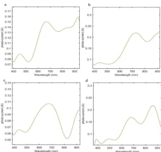
It seems that in these structures the plasmonic-photonic interaction can manipulate the light intensity into the solar cell, and consequently the related photo-current can be dramatically improved. It should be noted that the original aim was to manipulate the interaction of light with the solar cell structure, which was done by changing the NPs’ morphology. With changes such as size and type and as well as medium materials, the plasmonic features are altered. It contributes to the plasmonic engineering or plasmonic hybridization [20, 21]. Additionally, plasmonic-photonic interaction can be considered. In fact, by engineering the latter case, non-uniformity will be controlled, which affects the solar cell parameters. By these selections, improved parameters such as the related I-V curves, photo-current, and the distribution of intensity into the solar cell are presented. Initially, we started with photo-current for four different structures illustrated in Fig. 3, which is shown in Fig. 4. In Fig. 4(a) the average of current is about 0.14 A and for Fig. 4(b) it is about 0.21 A; for fig. 4c it is smaller than 0.1 A, and finally, for Fig. 4(d) it is about 0.17 A.
Fig. 4. Photo-current curves for different structures at different wavelengths from visible to NIR wavelengths. a) and c) for spherical NPs and b) and d) for tri-angular NPs
The average data can be compared with the traditional case in Fig. 1c. It is shown that the photo-current is improved in the case of Figs. 4(a), (b), and (d). It contributes to the plasmonic-photonic interaction and producing field non-uniformity by NPs. Indeed, the NPs’ plasmonic coupling to the far-field causes more light trajectories inside of the solar cell; and this clearly leads to the high absorption by carriers based on Eq. 9. In fact, the transport equations will be manipulated by the NPs’ plasmonic effect on carrier generation in Eqs. 6 and 7. Particularly, in Fig. 4(b) the maximum amount of photo-current occurred; and moreover, a good profile was attained for Fig. 4(a). In this structure the optimum level of the NPs’ plasmonic field can be coupled to the far-field region, which causes the maximum effect on the carrier generation. By interaction of the chain of plasmonic NPs with an incidence electromagnetic wave, the NPs plasmonic field interacts with the photonic mode of chain (geometry). This interaction creates the lattice plasmon which is due to the constructive interference of the NPs’ field. So, at any point in space, we can calculate the NPs’ field interference which is the main reason to coupling to far-field. By the way, the lattice plasmon optical properties are severely limited due to the photonic mode and geometry. This restriction defines at which wavelengths the constructive interference can be occurred [22-23]. We just need to manipulate the field non-uniformity inside the solar cell, by the NPs’ plasmonic field and its interaction with
photonic structure, to affect the carrier generation rate. It should be noted that the noisy behavior in this figure relates to the numerical approximation. Actually, due to using the finest mesh by COMSOL for the highest accuracy and link to MATLAB for I-V curve analyzing, we could not use a continuous form of wavelengths between 400 nm and 900 nm. This means that we have to use some important wavelengths; so the discontinuity or noisy behavior in this figure is inevitable. In the following, the related I-V curves are presented in Fig. 5.
Fig. 5. I-V curves for different structures at different wavelengths from 400 nm to 950 nm. a) and c) for spherical NPs and b) and d) for tri-angular NPs
Due to the best characteristics of photo-current in Figs. 4(a) and (b), we focused on exploring these structures and compared them with other cases. The modeling results show that the current in Fig. 5(b) reaches 0.35 A and is more effective than the traditional case in Fig. 1(b). The I-V curves are derived from Eqs. 11 and 12. We used the well-known iterative Newton-Raphson method to find the coupled equation roots. It was found that the calculated current for the improved structures was severely influenced by the NPs’ effect and as well by the light incidence wavelength. Actually, the NPs’ plasmonic effect and the non-uniformity produced by them inside of the solar cell, for instance in Fig. 5(b), have a dramatic effect on output current. Based on these data, the fill factor simulations are illustrated in Fig. 6.
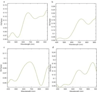
Fig. 6. Fill-factor curves for different structures at different wavelengths from visible to NIR wavelengths. a) and c) for spherical NPs and b) and d) for tri-angular NPs
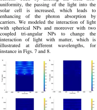
Fig. 7. Spherical NPs plasmonic effect on propagation of light in solar cell structure: a) 537 nm, b) 653 nm, c) 785 nm, and d) 854 nm.
The alteration in this figure is based on the
related photo-current in Fig. 4 for each
structure; so with regard to this parameter, the
maximum efficiency can occur for
structure3(b). Consequently, the major reason for this
end will be presented. We thought by
manipulation of the intensity distribution in the
solar cell structure, its critical parameters such
as photo-current and fill factor could be
managed. In other words, the NPs’ plasmonic
field coupling to the far-field or the field
non-uniformity created by this phenomenon has a
severe effect on carrier generation and output
current. Then by altering the field
non-uniformity, the passing of the light into the
solar cell is increased, which leads to
enhancing of the photon absorption by
carriers. We modeled the interaction of light
with spherical NPs and moreover with two
coupled tri-angular NPs to change the
interaction of light with matter, which is
illustrated at different wavelengths, for
instance in Figs. 7 and 8.
Fig. 8. Tri-angular NPs plasmonic effect on propagation of light in solar cell structure: a) 537 nm, b) 653 nm, c) 785 nm, and d) 854 nm
It is notable that the original aim was to explore the plasmonic generated by Au NPs and its photonic interaction in the far-field region. This means that by changing the morphology structure such as NPs’ inter-distance, the plasmonic-photonic interaction can be altered. Also, the optimum NPs’ inter-distance was selected. Moreover, the plasmonic-plasmonic interaction between two closed tri-angular NPs was investigated, and it can be concluded that the more efficient manipulation of light interaction with matter occurred for this structure, which is shown in Fig. 8. Furthermore, in Figs. 7 and 8, the effect of different wavelengths was investigated. In these figures, it is notable to mention the plasmonic-photonic coupling effect on light penetration into the solar cell. By this effect the non-uniform electric field is produced in the solar cell, which is unlike the traditional solar cell, and this is the main reason to create the high-efficiency solar cell system. Finally as an important result, it can be mentioned that by using the NPs with different morphology, 1) the light absorption by the new structure is increased; and 2) the field distribution (non-uniformity and its amplitude) into the solar cell is changed. These
factors relate to the NPs’ plasmonic features and the plasmonic-photonic coupling properties, and by changing these factors the solar cell efficiency can be altered.
IV.
CONCLUSION
In this study, it was shown that the NPs generating near-field electromagnetic waves severely affected optical power, which handles the carrier generation in the solar cell equations. In other words, by manipulating plasmonic properties of NPs (shape and density) and their effect on photons in solar cell structure, distribution of electromagnetic fields in solar cells is altered. By manipulation of these factors the solar cell’s critical parameters such as I-V curve, photo-current, and fill factor improved. The simulation results showed that for improving the fill factor or I-V curves, as the important parameters in solar cells, the alteration of morphology and NPs’ inter-distance are necessary.
REFERENCES
[1] S. Pillai, K.R. Catchpole, T. Trupke, and M. A. Green,"Surface Plasmon enhanced silicon solar cells," J. Appl. Phys.. Vol. 101, pp. 093105 (1-8), 2007.
[2] J.O. Schumacher, "Numerical simulation of silicon solar cells with novel cell structure," PhD thesis, University of Konstanz, 2000.
[3] P. Spinelli, V.E. Ferry, J. Groep, M. Lare, M. A. Verschuuren, R.E. I.Schropp, and H.A. Atwater, "A.Polman, Plasmonic light trapping in thin-film Si solar cells," J. Opt., Vol. 14, pp. 024002 (1-12), 2012.
[4] J. Jung, T. Søndergaard, T. Garm Pedersen, K. Pedersen, A.N. Larsen, and B.B. Nielsen, "Dyadic Green’s functions of thin films: Applications within Plasmonic solar cells," Phys. Rev. B, Vol. 83, pp. 085419 (1-14), 2011.
[5] S. Tembhurne, M. Dumortier, and S. Haussener, "Heat transfer modeling in integrated photo electrochemical hydrogen generators using concentrated irradiation," IEEE Proceedings IHTC15, Vol. 15, pp. 9526 (1-13), 2014.
[6] J. Yang, J. You, C. Chen, W. Hsu, H. Tan, X. W. Zhang, Z. Hong, and Y. Yang, “Plasmonic Polymer Tandem Solar Cell,” ACS NANO, Vol. 8, pp. 6210–6217, 2011.
[7] M.A. Green and S. Pillai, “Harnessing Plasmonics for solar cells,” Nat. photon. Vol. 6, pp. 130-132, 2012.
[8] V.E. Ferry, L.A. Sweatlock, D. Pacifici, and H.A. Atwater, "Plasmonic nanostructure design for efficient Light coupling into solar cells," Nano Lett. Vol. 8, pp.4391–4397, 2008.
[9] R. Guo, H. Huang, P. Chang, L. Lu, X. Chen, X. Yang, Z. Fand, B. Zhu, and D. Li, "Coupled optical and electrical modeling of thin-film amorphous silicon solar cells based on nanodent Plasmonic substrates," Nano energy, Vol. 8, pp. 141-149, 2014.
[10]Y.A. Akimov, W.S. Koh, and K. Ostrikov, "Enhancement of optical absorption in thin-film solar cells through the excitation of higher-order nanoparticle Plasmon modes," Opt. Express, Vol, 17, pp. 10195 (1-11), 2009.
[11]S.D. Standridge, G.C. Schatz, and J.T. Hupp, "Toward Plasmonic Solar Cells: Protection of Silver Nanoparticles via Atomic Layer Deposition of TiO," Langmuir, Vol. 25, pp. 2596-2600, 2009.
[12]W. Jiang, D.S. Ginger, M. Salvador, and S.T. Dunham, "Optics and Device Simulation of Surface Plasmonic Enhancement of Organic Solar Cell Performance using Silver Nano-Prisms," The Int. Conf. Simulation of Semiconductor Processes and Devices, SISPAD 2012, September 5-7, 2012, Denver, Colorado, USA, Vol. 7, pp. 245-249.
[13]T.F. Villesen, "On the Enhancement of Light Absorption in Si Solar Cells by Front-Side Plasmonic Scattering," PhD Thesis science and technology Aarhus University, (2014).
[14]Y.P. Singh, A. Kumar1, A. Jain, and A. Kapoor, "Enhancement in Optical Absorption of Plasmonic Solar Cells," Renew Energ J. Vol. 6, pp. 1-6, 2013.
[15]S.S. Verma, “Plasmonic solar cells,” The Ministry of New and Renewable Energy (MNRE), India , AKSHAY URJA J. Vol. 7, pp. 22-26, 2013.
[16]K.R. Catchpole, "A. Polman, Plasmonic solar cells," Opt. Express, Vol. 16, pp. 21793- 21800, 2008.
[17]U.W. Paetzold, K. Bittkau, M. Meier, R. Carius, and U. Rau, "Simulation-Based Analysis of Plasmonic Light Trapping in
Thin-Film Silicon Solar Cells," NUSOD 13th
International Conference, Vol. 22, pp. 1-2, 2013.
[18] M.B. Eteiba, E.T. El. Shenawy, J.H. Shazly, and A.Z. Hafez, "A Photovoltaic (Cell, Module, Array) Simulation and Monitoring Model using MATLAB®/GUI Interface," Int. Journal of Computer Applications, Vol. 69, No. 6, pp. 0975 – 8887, 2013.
[19]T. Salmi, M. Bouzguenda, A. Gastli, and A. Masmoudi, "MATLAB/Simulink Based Modeling of Solar Photovoltaic Cell," Int. J. Energy Res. Vol. 2, no. 2, pp. 213–218, 2012.
[20]A. Salman Ogli and A. Rostami, “Investigation of Surface Plasmon Resonance in Multi-layered Onion-Like Hetero nano crystal Structures,” IEEE Trans. on Nanotechnology, Vol. 12, pp.831-538, 2013.
[21]A. Salman Ogli and A. Rostami, “Plasmon Modes Hybridization Influence on Nano-Bio-Sensors Specification,” IEEE Trans. Nanotechnology, Vol. 12, pp. 558-566, 2013.
[22]M.B. Ross, C.A. Mirkin, and G.C. Schatz, “Optical properties of one, two, and three-dimensional arrays of plasmonic nanostructures,” J. Phys. Chem. C, Vol. 120, pp. 816-830, 2016.
[23]S. Zou, N. Janel, G.C. Schatz, “nanoparticle array structures that produce remarkably narrow plasmon lineshapes,” J. Chem. Phys. Vol. 120, pp. 10871-10875, 2004.