Computer Aided Design & Experimental Validation of Engine Metal pallet
Manoj P. Talele
Mechanical Engineering Department,
MIT, Aurangabad (M.S), India.
Ashok J. Keche
Associate Professor,
Mechanical Engineering Department,
MIT, Aurangabad (M.S), India.
Abstract
In industrial transportation, material handling and packaging plays an important role. To achieve the faster transportation new approach is needed. This requires the material handling without the damage of main product. In production process different types of small and larger types of pallets are used for transportation. The 3D concept design of engine handling metal pallet for both internal storage and external transportation is designed and validated, easy to assembly and disassembly processes with manufacturing variable techniques are discussed with proper and safe transportation. For designing the pallet, standard procedure is adopted in worldwide. But it’s not suitable in every case like the dissimilar shape of finished product. The proposed model is a combination of standardize process and the simplicity ideas
Keywords: 3D cad design of metal pallet, Concept design of engine pallet, Engine metal pallet, Metal rack, Experimental validation of metal pallet.
1. Introduction
The basic purpose of pallet design is to safely transport the engine with safe handling procedure. Also focus on those points that are involved in the engine peripheral safety in packaging. In industry different types of pallets are used. Like wooden pallets, metal pallets and plastic pallets. After the consideration of the pros and cons pallet packaging material is to be decided. But in such country the wooden pallet and plastic pallets tear down is very difficult. And in this situation the many companies are prefer the metal pallet for transportation.
The metal pallet is subjected to under the stresses of compression, tension and bending, when the pallets moved from one place to another place with the engines. The material selection with standard sections is depends upon the primary criteria of engine load.
To keep a fine balancing between engine and pallet design optimization of weight is required. Therefore normally the overall peripheral design of engine needs to be considered in designing of pallet for engine.
This paper dealt with design concept of multi cylinder engine pallet. It also included with pallet CAD modeling for ease to assemble engine.
1.2 History of pallets
It is the structural foundation and sustains the unit load which allows to handle and storage efficiently. Finished goods or shipping containers are often placed on a pallet secured with strapping, stretch wrap or shrink wrap and shipped.
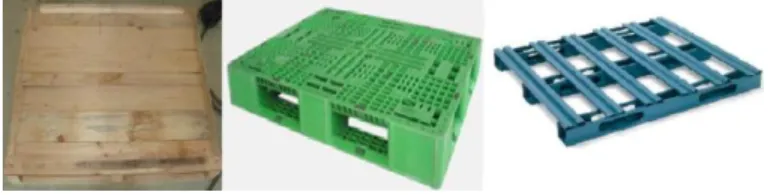
In general most pallets are wooden pallets can also be made of plastic, metal, and recycled materials. Each material has advantages and disadvantages relative to the others.
Figure1 Wooden pallet, plastic and metal pallet
In figure 2 shows the wooden pallets with engine packaging for external transportation. This type of packagings was to used from the earlier decades. This process is manual process and its take long time for packaging. Because every wooden riff is to assembled by nailing process and the card board box assembled on it. Due to long time duration and this process is lengthy at continuous production.
pallet and card board box packing inside the containers with nylon taps
2. Literature review
Claudio Bernuzzi et al [1] part 1 deal with the selection of the method of analysis, i.e. 1st or 2nd order elastic analysis, depending on the rack deformability to horizontal loads. Internal forces and moments on members are significantly influenced by the effects of lateral displacements as well as by the type of the beam formulation adopted in the finite element analysis program. Static design rules currently adopt in Europe for steel storage pallet racks. No univocal rules are provided by the European Rack code for routine design. The system length approach for buckling check leads to unsafe design. Improvements for the evaluation of the elastic critical load are urgently expected. Claudio Bernuzzi et al [2] theoretically studied the design of rack and consider serviceability lateral displacements of the whole rack and both resistance and stability ultimate limit states for the uprights. Underline the weak points of the European rack standards and are of practical interest for structural engineers, stressing clearly when the recommended procedures fail, hence leading to an unsafe and uneconomic design. Benoit P. Gilbert et al [3] improved 2D model to accurately reproduce the bending moment distributions obtained using 3D advanced finite element analysis. Improve the 2D model of steel drive-in racks. The effect of pallets on the bending moment distribution in the uprights is checked. The influence of the pallets on the capacity of the racks is investigated. This paper clarifies the loading scenario(s) governing the design. The strength of a device required to prevent the pallets from sliding is determined. Sangle et al [4] worked on the elastic stability analysis of cold-formed pallet rack structures with semi-rigid connections. With the help of experimental study & FEA is carried out on Pallet Rack Structure. It also includes three dimensional finite element modeling and elastic buckling analysis. Original open upright sections are torsionally strengthened by external stiffeners. External stiffeners are found very useful for increasing the load carrying capacity. To calculate accurate buckling load, 3-D finite element modeling is recommended.
Teh et al [5] designed double-sided high-rise steel pallet rack frames and made analysis with the help of 3D linear buckling analyses; it demonstrated that the global buckling behavior of high-rise steel storage rack frames may not be revealed by 2D buckling Analyses as 3D interaction modes are involved. Soury et al [6] worked on the Design, optimization and manufacturing of wood–plastic composite pallet. FEA and experimental method use for optimize the design of an I-shape profile with wood–plastic composite (WPC) pallet. Comparison of simulations and experimental results indicated that the given (WPC) design method is reasonably reliable.
Brown [9] studied the seismic design of pallet racking systems and calibrated according to the experimental results. And found that thin walled cold formed sections are not generally considered suitable for plastic deformations, or resistance to seismically induced loadings. Design approaches suggested that will enable the capacity design requirements of to be considered, while keeping with the cold formed sections traditionally used for pallet rack construction. Mitzner et al [10] studied the Metal and wood composite design and using the Experimental -Impact test, provide design information for ease choosing appropriate panel for application, metal with plywood overlays. Baldassino et al [11] conducted the analysis of the experimental monotonic test & results shows that the beam to column joints are very flexible, to the cyclic tests, it has been pointed out the relevant differences in the form of the hysteresis loops of rack joints in comparison with the ones associated with traditional steel components and the non-negligible influence of the connection systems on the joint behavior. This stresses the importance of the definition of an appropriate design philosophy for pallet racks in seismic zones.
From the above literature review it is found that the chance to increase the study in 3D cad modeling with concept design for special requirement of pallet. Also need to improvement in the metal pallet for storage and transportation of engines.
Many of the researchers are worked on the static condition modeling of steel rack with the rack joint by nut and bolts.
This paper focuses on the concept design, check with FEA analysis, result validated by experimentally.
3 Design considerations
Design related consideration is required before the pallet model preparation. Once it finalized model checked with FEA analysis.
Followings are the some of the metallic pallet design consideration for special requirements like engine transportation.
3.1 Material of pallet
Generally steel pallet made from the cold rolled steel sheet. This material is suitable for sheet metal bending, punching operation etc. As well as standard steel hollow square sections according to the IS 4923:1997.
3.2 Channel selection
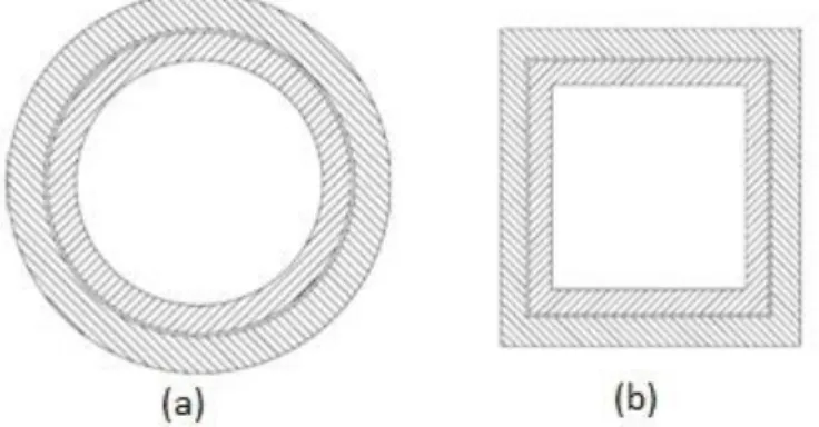
Generally the circular pipes are easily available on the market. Therefore it is easy to prefer circular hollow pipe for the pallet side column design. In addition it’s available in standards size. Selection of appropriate diameter & thickness of circular pipes in pair for insertion is important.
Alternatively the square hollow channel tube is the better pair option for the insertion. Because of square channel has flat faces are directly contact with the side channels. Therefore for guiding and welding fully contact area available. Figure 3 (b) shows the square hollow channel cross section of tube engagement.
3.3 Engine packaging precautions
Following are the engine packaging precautions
1. Engine is properly mounted on the pallet with fasteners
2. Suitable tighten torque apply on the bolting and verify it.
3. Use the vibro mount if it is necessary in design so reduce the vibration in transport
4. Electrical system like wiring harness well pack with tie
5. Pressure sensor, temperature sensor terminals protect with guards
6. Radiator front side protect with the cardboard paper
7. Engine coolant line is properly sealed or caped
8. Fuel lines are properly tied and protected.
9. Remove the fuel from fuel filter before the transportation and protected fuel filter from protection cover.
3.4 Engine mounting provision for pallet
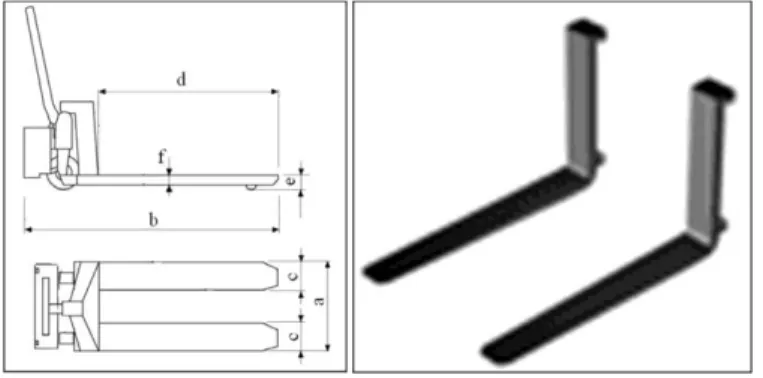
Figure 4 Engine mounting Legs
Preferably engine leg is design according to the crankcase mounting holes provision and peripheral component constraint. These legs are mounting on the pallet and locking with nuts and bolts.
3.5 Internal and external transportation
Internal transportation used the powered fork lift trucks. Meant for designing the pallet use the fork dimensions. Important dimensions of fork in figure 5.
For external transportation used the fork truck for transportation. This fork is adjustable as compare to the manual fork lift. And these dimensions and movement of fork is to be specified and standards all over.
Figure 5 Power fork lift truck dimensions
3.6 Easy to assembly and disassembly
On engine assembly line limited time for the engine packaging and dispatch. Therefore engine assemble and disassemble on the pallet easily. It also considers the overall space limit so the more than one engines assembled on single pallet.
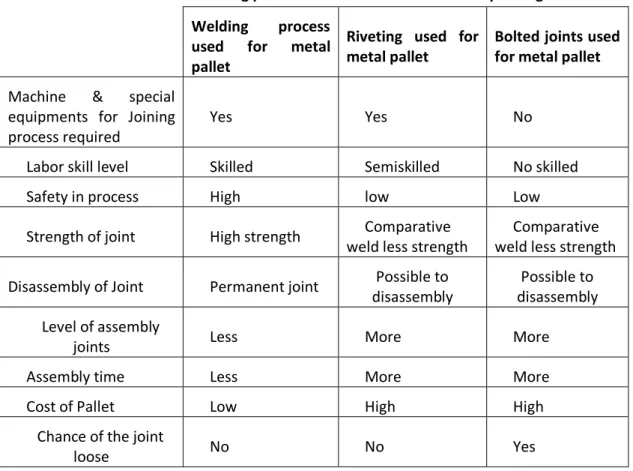
3.7 Manufacturing Process selection
Table 1 Manufacturing process selection criteria for concept design
Welding process used for metal pallet
Riveting used for metal pallet
Bolted joints used for metal pallet
Machine & special equipments for Joining process required
Yes Yes No
Labor skill level Skilled Semiskilled No skilled
Safety in process High low Low
Strength of joint High strength Comparative
weld less strength
Comparative weld less strength
Disassembly of Joint Permanent joint Possible to
disassembly
Possible to disassembly
Level of assembly
joints Less More More
Assembly time Less More More
Cost of Pallet Low High High
Chance of the joint
loose No No Yes
3.8 Special pallet requirements
Special Pallets are required for the variable shape of finished product packaging. Engine properly fitment, locking is essential to safely transportation. Pallets are used for the multipurpose use. Some time it’s used only for the internal transportation, like trolley and wheels type. Sometime it’s only for storage or only for assembly line raw material handling.
4. Pallet size & weight calculation
4.1. Pallet size calculationPallet size is depends upon the following various factors,
1. Engine overall size
2. Feasibility to assembly and disassembly of the engine on pallet. Means space for tightening the engine mounting bolts.
3. Floor area to storage the pallets.
4. Engine qty per pallet
5. Fork insertion and resting area also to be consider for height calculation of pallet
6. Engine quantity in container for space constrain.
8. Pallet weight & engine weight consideration for the balancing and storey levels of pallets
9. Engine CG is required for the balancing of pallet.
Standard container size and weight is the main constrain of pallet size finalization. Example of pallet weight and size calculation is given below.
Standards size of container according to the CTU guideline,
Table 2 Container 40 feet standard size
40 ft. Standard Container
Dimensions Length Width Height
Internal 12022 2352 2395
Below is the concept of pallet fitment in the container with the two by two rows.
Figure 6 L x W x H Size of container and Internal Gap between two pallet rows
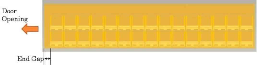
Figure 7 End gap after the all pallets packaging inside the container
= 10 X 2 X 2
= 40 Nos. of pallets are assembled inside the one container If the engines per pallet is 4 quantity,
Nos. of engines per container = Number of pallets per container X Number of pallets per container = 4X40
=160 Nos. of engine dispatch in one time in single container.
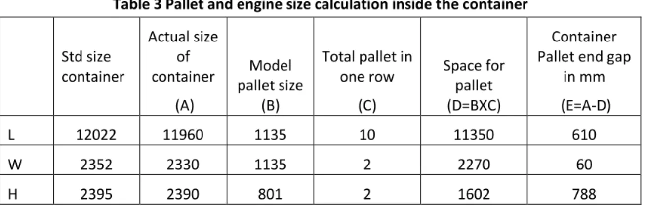
Table 3 Pallet and engine size calculation inside the container
Std size container Actual size of container (A) Model pallet size (B)
Total pallet in one row (C) Space for pallet (D=BXC) Container Pallet end gap
in mm
(E=A-D)
L 12022 11960 1135 10 11350 610
W 2352 2330 1135 2 2270 60
H 2395 2390 801 2 1602 788
Total no of engines per row is 40 and total no. of engines in container is 160 nos. On the above data seen that concept model pallet size (B) is sufficient and end gap also enough for handling.
4.2. Weight calculation
Standards 40 feet length container max pay load is given below. According to this limit engine and pallet load calculation is shown below.
Table 4 40 Feet container max payload
Weight
Max. payload 26580 kg
Table 5 Total weight calculation for container
Total engines weight inside the container 100 X 160 16000 kg
Total pallets weight inside the container 70 X 40 2800 kg
Total engines + Pallets weight 18800 kg (Approx.)
5 Pallet concept design
Engine transportation usage on flat plastic or metal pallet (Figure 1) is difficult because locking provision not available on it. Engine quantity per pallet is depending on the size and weight. That means single, double or four engines per pallet.
Welding is the one of the best method of joining. Welded joint is good strength than the bolted joints. Below figure 8 shows the concept of welded type of pallet. This type of pallets are beneficial because of minimum time involve for pallet assembly and manufacturing
Only one drawback is it cannot be dismantle with all joints similar to the bolted joints.
Welded type pallet is better strength therefore this type of pallet is helpful for the small capacity engines transportation.
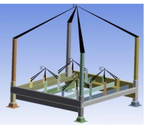
Figure 8 Welding concept pallets for four engine mounting
In figure 8 four engines mounting provision on the single pallet and the storey building at two, three and four level.
5.2 Concept for of engine locking at storey build
Figure 9(a) Level 2 storey pallets for container (b) Locking provision of vertical hollow square bar
Pallet storey building is to be considering at the time of concept design. The above figure 9(a) shows the two storey pallets are placed for the container packaging. Design it should be locked with each other means whenever it move it cannot be crash.
In figure 9(b) shows the simple designed locking pin with self locking concept alternatively standards locking pins are available in the market.
Assembly and disassembly is also important in the engine transportation pallet due to the space constrain in continues production.
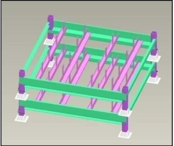
Figure 10 Welded engine pallets after disassembly
The above figure 10 shows the pallet disassembly after removed vertical square hollow bar. This is the advantages of the minimum space requirement in storage area after it use.
5.4 Welding fixture for weld & Quality check
In welding type pallet accuracy of engine mounting legs is very important. Because, if dimensions are deviated its damage the thread of engine mounting.
Therefore the checking fixture required before the engine direct assembly on pallet. Below figure 11 is the four mounting provision checking fixture.
Fig. 11 assembly fixture before the engine assembled
FEA analysis conducted in the Ansys software. Followings are the primary results observed on welded metal pallet.
Analysis conducted for the handling and fork lifting conditional stress plot with applying specific load.
Figure 12(a) Max stress at the end of the bottom cup (b) Max stress at the center of the channel
Analysis Intent
Analysis
Type Load KN
Deformation Stress (mm) (MPa)
1 Handling Stock Structural 8.397.36 2.7112 242.5
2 Stacking Check Structural 16.794 0.1587 238.1
3
Forklift supporting
check Structural 8.397.36 1.7354
302.02
On the above result stress observed higher than the yield stress 240 Mpa.
As per the above result following changes are corrected in the model.
1. Increase thickness of bottom cups.
2. Introduce guide member into cups for more stability against wobbling of upper pallet.
3. Increase thickness of transverse members
4. Replace current engine legs with a L-shaped member instead.
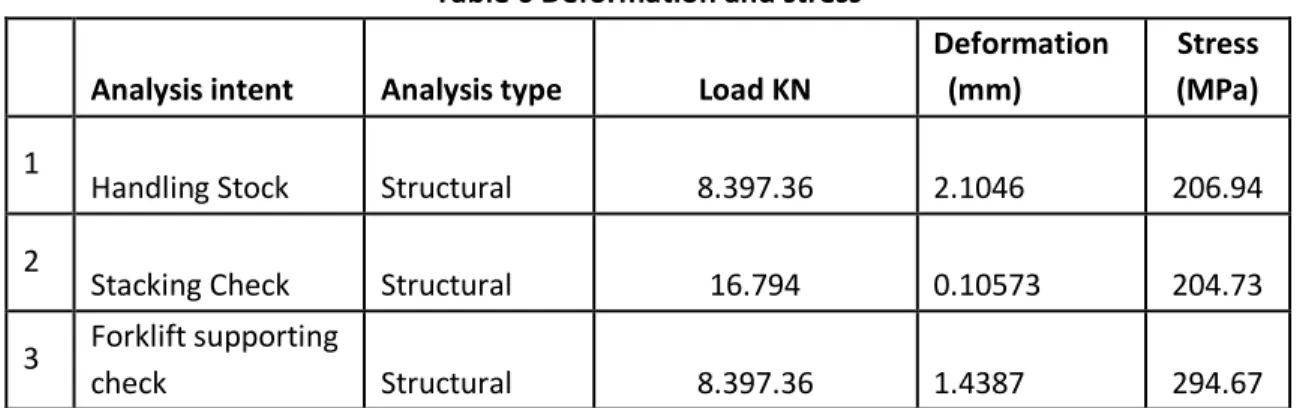
Table 6 Deformation and stress
Analysis intent Analysis type Load KN
Deformation (mm)
Stress (MPa)
1
Handling Stock Structural 8.397.36 2.1046 206.94
2
Stacking Check Structural 16.794 0.10573 204.73
3 Forklift supporting
check Structural 8.397.36 1.4387 294.67
After the correction above graph shown the better result and design is freeze for the proto development.
7 Experimental setup
In experimental analysis two types of setup prepared. One is for the handling and fork lifting deflection check in the main engine mounting member and another for the stationary stacking up to 4 levels setup.
In the below figure 14 the four engines are mounted on the pallet. Pallet is under the loaded condition. Loading condition is the same considered as in analysis.
7.1 Handling stock & fork lifting
Table 7 Load and deflection result in the main engine member
Engines per pallet Load kg Load in KN
Deflection mm (y Max.)
1 143 1.40283 0.3
2 238 2.33478 0.8
3 333 3.26673 1.4
4 428 4.19868 1.8
Double storey with 8
engines 856 8.39736 2.7
Load considers in the kg and test carried out on single pallet and double storey level of pallet.
7.2Stacking check
Figure 15 Setup for Engine mounting channel deflection
Table 8 Load vs. deflection result of engine mounting main member
Engines per pallet Load Kg Load in KN
Deflection mm (y max)
1 143 1.40283 0.1
2 238 2.33478 0.15
3 333 3.26673 0.164
4 428 4.19868 0.17
Same the figure 15 shows the stacking deflection when engines are mounted on the pallet means under loaded condition.
8 Result & Discussion
Table 6 shows the stress produced in the engine mounting member are more than the yield stresses 240 Mpa. After the modification in the model table 7 shows obtained stress is under the yield stress. That means the model is under the safe condition. This deflection results check with the experimentally. This test is carried out only the handling, fork lifting and the stacking condition. Deflection result table 7 is the maximum 2.1mm in handling and the actual deflection measured is the Max 2.7 mm it included manufacturing flatness of the channel. As well as stacking result is also similar in both case.
And figure 16 and figure 17 is the load verses deflection graph plotted at Handling stock with fork lifting and stacking respectively.
Welded pallet design is suitable for small and large quantity of engines to dispatch. Selection of the pallet assembly process is to be direct effect on cost and weight.
The 3D CAD model of the metal pallet is prepared on the Pro-E wildfire software. After development of model the CG is found out. Parametric design a pproach is used of modeling of metal pallet. The round, corners and joints are smooth and minimize the concentration inside the pallet model. Include the chamfers at bolt hole are removed in order to reduce the model meshing problems & size. It can be expected that these simplification would lead to great amount of savings in the solution time, without compromising on the accuracy of the solution. The Steel pallet mass is measured on 3D software for analysis. 42.7 Kg weight observed on the software.
8 Conclusions
On the analysis result and the practical work it seen that the welded design is safer in the small capacity engine at large qty transportation. Because of strength, reused and recycled are the benefits of this type of pallet.
Experimental result and analysis result approximately match. Just small variation observed due to the setup arrangement constrain. Therefore we have to conclude that this type of pallet is safer for the transportation and storage of engines.
Overall the special pallets designs are depend on the base of the engine mounting provision that is available on the engine crankcase and the space is the limitations. Also seen that in the conceptual stage it is necessary to consider the engine packaging, pallet manufacturing process, storage and space constrain, container fitment, per quantity of engine on pallets etc.
References
[1] Claudio Bernuzzi, Armando Gobetti, Giammaria Gabbianelli, Marco Simoncelli (2014),” Unbraced pallet rack design in accordance with European practice–Part 1: Selection of the method of analysis”, Thin-Walled Structures, Vol.117 pp.78-82.
[2] Claudio Bernuzzi, Armando Gobetti, Giammaria Gabbianelli, Marco Simoncelli (2014),” Unbraced pallet rack design in accordance with European practice–Part 2: Essential verification checks”, Thin-Walled Structures, Vol.117 pp.82-87.
[3] Benoit P. Gilbert, Lip H. Teh, Romain X. Badet, Kim J.R. Rasmussen (2014),” Influence of pallets on the behaviour and design of steel drive-in racks”, Journal of Constructional Steel Research, Vol. 97, pp.10-23.
[4] Keshav K. Sangle, Kamal M. Bajoria, Rajshekar S. Talicotti (2012),” Elastic stability analysis of cold-formed pallet rack structures with semi-rigid connections”, Journal of Constructional Steel Research, Vol. 71, pp.245-262.
[5] Lip H. The Gregory J. Hancock (2004),” Analysis and design of double-sided high-rise steel pallet rack frames”, frames. Journal of Structural Engineering, Vol. 130(7), pp. 1011-1021.
[6] E. Soury, A.H. Behravesh, E. Rouhani Esfahani, A. Zolfaghari (2009),” Design, optimization and manufacturing of wood–plastic composite pallet”, Materials & Design, Vol. 30, pp.4183-4191.
[7] M.H.R. Godley, R.G. Beale (2008),” Investigation of the effects of looseness of bracing components in the cross-aisle direction on the ultimate load-carrying capacity of pallet rack frames ”, Thin-Walled Structures, Vol. 46, pp.848-854.
[8] Hande Yaman, Alper Şen (2008),”Manufacturer’s mixed pallet design problem”, European Journal of Operational Research, Vol. 186, pp.826-840.
[9] B.J. Brown (1983),” seismic design of pallet racking systems”, Third South Pacific Regional Conference on Earthquake Engineering, Wellington.
[10]R.C. Mitzner, P. W. Post, G.A. Ziegler (1979),” Metal and wood composite design”, SAE international.