MICROCONTROLLER BASED OPEN-LOOP SPEED CONTROL
SYSTEM FOR DC MOTOR
Akhilendra Yadav* Gurleen Kaur* Akanksha Sharma*
ABSTRACT
This paper presents open loop speed control scheme for the speed control of a permanent
magnet DC motor using an AVR Microcontroller. The microcontroller has been programmed
to automatically vary the duty cycle of the H-bridge chopper depending upon the set/required
speed of the motor. The chopper is driven by a high frequency PWM signal. Controlling the
PWM duty cycle is equivalent to controlling the motor terminal voltage, which in turn adjust
directly the motor speed. The PC interfacing has been done using serial port (DB9
Connector). Experimental results show that proposed system is suitable for different
industrial applications such as trolley buses, subway cars, or battery-operated vehicles.
Keywords: Microcontroller, PWM, Speed control.
I. INTRODUCTION
interfacing. A 12V, 300W, 2400 rpm permanent magnet dc motor and 5v, 500mA regulated power supply has been used
II. THE
PERMANENT
MAGNET
DC
MOTOR
AND
ITS
CONVERTER
The speed of the motor can be varied by varying the armature voltage in the constant torque region or by varying the field flux in the constant power region to achieve below rated and above rated speeds respectively. The ability to produce high torque at low speeds and compact size makes PMDC motor suitable for many applications.
Fig.1. Speed-Torque Characteristics of PMDC Motor
Speed of the PMDC motor is proportional to voltage and torque is proportional to current and it can generate high torques, typically 10 to 12 times the rated torque. Speed torque characteristics of PMDC motor are as shown in the fig.1. Speed can be controlled by varying the voltage applied to the armature. In this paper voltage control is used which is obtained with the help of H-bridge chopper as shown in the fig. 2 & 3.
Fig. 3. Four quadrant operation
This paper presents two modes of operation i.e. first and third quadrants by operating switches S1, S2, S3 and S4 in different order. The motor rotates in clock wise direction in first quadrant (S1-ON, S4-ON) and anti-clock wise in third quadrant (S2-ON, S3-ON).
III.
HARDWARE
DESIGN
A. Mechanism of DC Motor speed control
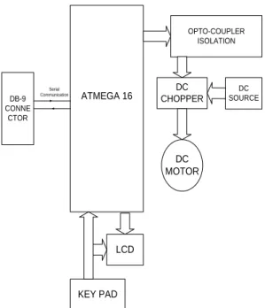
The ATMEGA-16 Microcontroller implements the control algorithm according to the speed given through the keypad. Port-B pins PB3 and PB4 are given for driving the L293D Chopper IC. The Opto-coupler MCT2E is used to isolate the high voltage circuit from the low voltage controlling signals. The user can give commands through the keypad for running the motor either clockwise or anticlockwise directions. A digital Tachometer is used to measure the speed of the motor.
ATMEGA 16
DC MOTOR
OPTO-COUPLER ISOLATION
DC CHOPPER
DC SOURCE
KEY PAD LCD
DB-9 CONNE
CTOR
Serial Communication
B. H-Bridge Chopper L293D
This device is a monolithic integrated high voltage, high current 4 channel designed to accept standard DTL or TTL logic levels and drive inductive loads and switching power transistors. To simply use as two bridges each pair of channels is equipped with an enable input. It is suitable for use in switching applications at frequency up to 5 KHz.
Fig.5. Connection diagram for L293D
A
B Description
0 0 Motor stops or Breaks 0 1 Motor runs Anti-clockwise 1 0 Motor runs Clockwise 1 1 Motor stops or Breaks
Table. 1. Truth Table for Chopper L293D
IV.
SOFTWARE
DESIGN
A. Algorithm for Speed control
The AVR Microcontroller can control speed of the DC motor accurately with minimum hardware at low cost. The MCU has inbuilt timer and counter register.
Fig. 7. Algorithm for Speed control
The algorithm shown in the fig.7 describes the speed control program which first initializes the timers and I/O ports then reads the commands from the keyboard. Each key is designated with a specific count which is equivalent to different duty cycles. On the basis of the count Microcontroller generates a PWM signal and the motor can be stopped by keying a specific character anytime.
B. Timer and its PWM Modes
Fig. 8.Waveform Generator
Fig. 9. PWM Signal generation
C. Fast PWM Mode Duty Cycle
Duty cycle can be calculated by using equation 1. The duty cycle can be determined using the OCR0 register, bigger OCR0 value results in a bigger duty cycle. When OCR0 is 255, the OC0 is 256 clocks out of 256 clocks, which means duty cycle is 100percent.
DUTY CYCLE
(1)
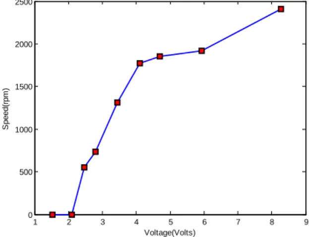
V.RESULTS
Figure 10 & 11shows speed variation for different duty cycles for clock wise and anti-clock wise rotation respectively. A linear speed Vs voltage curve is obtained.
1 2 3 4 5 6 7 8 9
0 500 1000 1500 2000 2500
Voltage(Volts)
S
peed(
rpm
)
-4 -3.5 -3 -2.5 -2 -1.5 -1 -0.5 0 0 500 1000 1500 2000 2500 Voltage(volts) S peed( rpm )
Fig.11. voltage-speed characteristics for Anti-clockwise direction
VI. CONCLUSION
The microcontroller based open loop dc motor speed controller system has been developed. Experimental result shows that microcontroller is a reliable instrument to control the motor with high precision. The proposed method reduces the number of components because the microcontroller can integrate in one package all the functions. The graph obtained from the experimental results is similar that of the permanent magnet dc motor. Thus, the proposed technique suited for industrial applications.
REFERENCES
1. T. Castagnet and J. Nicolai, “Digital Control for Brush DC Motor,” IEEE Transaction
on Industry Application, Vol. 30, No.4, July/August 1994.
2. Khoei and Hadidi, “Microprocessor Based Closed-Loop Speed Control System for DC Motor Using Power Mosfet,” 3rd IEEE International Conference on Electronics,
Circuits and Systems, ICECS, Oct. 1996.
3. Krishnan and Thadiappan, “Speed control of dc motor using thyristor dual converter,”
IEEE Transaction on industrial electronics and control instrumentation, Vol. 23, pp.
391-399, Nov. 1976.
4. Y. S. E. Ali, S. B. M. Noor, S. M. Bashi and M. K.Hassan, “Microcontroller Performance for DC Motor Speed control system,” National power and energy
conference, Malaysia, Dec. 2003.
5. A.H.M.S. Ula and J.W. Steadman, “Design and Demonstrate of a Microcontroller Control for an Industrial Sized DC Motor,” IEEE Transaction on Energy Conversion,
6. J. Nicolai and T. Castagnet, “A Flexible Microcontroller Based Chopper Driving a Permanent Magnet DC Motor,” Fifth European Conference on Power Electronics and
Applications, Rousset, 13-16, Sep. 1993.
7. B.Haas, M. Etezadi-Amoli and D. McPherson, “An Inexpensive Imbedded Motor Controller using a Tachometer Feedback,” 38th IEEE conference on power
symposium, NAPS, North America, 17-19, Sep.2006.
8. Carmadi Machbub, Ary Setijadi Prihatmanto and Yoseph Dwi Cahaya, “Design and Implementation of Adaptive Neural Network Algorithm for DC Motor Speed Control System using Microcontroller,” 4th IEEE International conference on Power
electronics and Drives sytems, Indonesia, 22-25, Oct. 2001.
9. Bimbhra. P.S., Power Electronics. New Delhi, Khanna Publishers, 2006.