International Journal of Research in Engineering & Applied Sciences
Email:- [email protected], http://www.euroasiapub.org
30
Parameters Effecting Substation Grounding Grid Resistance
Dwarka Prasad
1,
Research Scholar,
Uttarakhand Technical University, Dehardun (Uttarakhand), India Department of Electrical Engineering
Laxmi Devi Institute of Engineering & Technology, Alwar, Rajasthan, India.
Dr.H.C Sharma
2Department of Electrical & Electronics Engineering
Vishveshwarya Institute of Engineering &Technology, Dadri, G.B.Nagar (U.P), India.
Abstract
: - One of the key parameters in substation grounding design is to calculate accurately the grounding resistance of the system. The substation grounding grid resistance to be used to design a safe grounding system has been receiving a lot of attention in recent years. It is important that the substation ground has a low ground resistance, adequate current carrying capacity, and safety features for personnel and equipment. A good grounding system provides a low resistance to remote earth in order to minimize the GPR. For most transmission and other large substations, the ground resistance is usually about 1 Ω or less. In smaller distribution substations, the usually acceptable range is from 1 Ω to 5 Ω, depending on the local conditions. In this paper the various parameters affecting the calculation of substation grounding grid resistance is briefly explained.Keywords: Grounding, Ground Resistance, Resistivity, Grounding Grids, Substation
I. Introduction
International Journal of Research in Engineering & Applied Sciences
Email:- [email protected], http://www.euroasiapub.org
31
Many formulas are proposed for the calculation of the substation grounding grid resistance. Most of these formulas are accurate within certain ranges of grid depths or grid sizes. Some of these formulas are recommended to be used for estimating the maximum fault current. Some are helpful in estimating the substation ground potential rise for preliminary design evaluation. For accurate calculation of the ground resistance of the grid, formula such as Schwartz formula should be used [6-13].II
.
Basic Components
and
Purpose of Grounding System
The grounding system consists of four basic components:
1.The soil beneath and around the substation site which is very complicated and heterogeneous in composition as well as in structures.
2.The ground grid which is a network of interconnected conductors embedded or buried beneath the substation surface. Usually, a typical substation ground system will take the form of a grid of horizontally buried conductors.
3.Ground rods connected to the ground grid and installed beneath the site, usually reaching lower resistivity soil to control the surface gradients and lower the overall grounding system resistance. 4.The finished surface covering the site, in most high voltage substations, a layer of crushed rock or gravel is applied to the surface.
The purpose of a grounding system at a substation, includes the following:
To provide the ground connection for the grounded neutral for transformers, reactors and capacitors.
To provide the discharge path for lightning rods, surge arrestors, spark gaps and other similar devices.
To ensure safety to operating personnel by limiting potential differences that can exist in a substation.
To provide a means of discharging and de energizing equipment to proceed with maintenance on the equipment.
To provide a sufficiently low resistance path to ground to minimize rise in ground potential with respect to remote ground.
III
.
Soil Resistivity and Ground Potential Rise
The grid resistance and the voltage gradients within a substation are directly dependent on the soil resistivity. Because in reality soil resistivity will vary horizontally as well as vertically, sufficient data must be gathered for a substation yard. The Wenner method is widely used [7]. When a grounding system is designed, the fundamental method to ensure the safety of human beings and power apparatus is to control the step and touch voltages in their safe regions. In different seasons, the resistivity of the surface soil layer would be changed, which would affect the safety of grounding system, and the grounding resistance, step and touch voltage would move to the safe side, or to the hazard side. In rainy season , the low resistivity soil layer leads the grounding resistance and the step voltage smaller than the respective values in normal condition, it is good for safety of human beings, but the raining season perhaps leads the touch voltage higher than its limit value, so the influence of raining on the safety of grounding grid should be considered.
International Journal of Research in Engineering & Applied Sciences
Email:- [email protected], http://www.euroasiapub.org
32
rod will slightly reduce the value of GPR. This indicates that the current density over the grid affects directly to the current distribution to the soil layer. Therefore, the design and construction of grounding grid in the area which the top soil-layer resistivity is less than the bottom-layer resistivity, can lessen the number of ground rod used in the grid because the value of GPR is insignificantly different. Finally, the deeper the grid buries in the layer, the lesser is the value GPR. Due to the different in soil characteristics at each substation, ground grid design must carefully be done to gain acceptable safety as well as optimal investment. From the past, ground grid design without rods and with rods was carried out. A vertical rod is more effective electrode than a horizontal rod. The rod length is varied to determine the influence of rod length on GPR, furthermore, when the soil structure is two-layer structure, the optimum ground layer depth and rod length for ground grid must be determined to gain safety and proper investment. Therefore, the study of ground grid buried in each layer depth is done to determine the effect of GPR [14-15].IV. Different Formulas For Calculating Grounding Grid Resistance
1.The formula given by Dwight [6] for calculating substation grounding grid resistance is:
Rg = 𝜌
4
𝜋
𝐴 (1)
where
Rg is the substation ground resistance in Ω
ρ is the soil resistivity in Ω.m
A is the area occupied by the ground grid in m2
2. An upper limit of the substation grounding grid resistance can be obtained by adding a second term to the above formula, as proposed by Laurent and Nieman, also called IEEE Std. 80 - 2000 formula [7] is given by:
Rg = 𝜌
4
𝜋
𝐴 +
𝜌
𝐿𝑇 (2)
LT is the total buried length of conductors in m
3. As per Nahman and Skuletich [8] the substation ground resistance can be obtained by the formula:
Rg = =𝜌 0.53 𝐴 +
1.75
𝐿 𝑛13 1 − 0.8
100 ℎ𝑑 𝑛 𝐴
1
4 (3)
Where,
n = the number of parallel conductors in one direction of the grid n = n’ +1
n’ = the number of meshes in one direction
4. The formula given by Schwartz [9] for calculating substation grounding grid resistance is:
Rg = 𝜌 𝜋𝐿 𝐼𝑛
2 𝐿 ℎ′ +𝐾1
𝐿
𝐴 − 𝐾2 (4)
Where,
International Journal of Research in Engineering & Applied Sciences
Email:- [email protected], http://www.euroasiapub.org
33
K1 = -0.04W +1.41 for h=0K1 = -0.05W +1.2 for h=
1 10 𝐴 K1 = -0.05W +1.13 for h=1
6 𝐴 W= Length / Width of the grid K2 = 0.15W +5.50 for h=0
K2 = 0.10W +4.68 for h=1
10 𝐴 K1 = -0.05W +4.40 for h=1
6 𝐴
5. The formula given by Sverak [10,11] for calculating substation grounding grid resistance is:
Rg =𝜌 1 𝐿𝑇 +
1 20 𝐴 (1 +
1
1+ℎ 20 𝐴 ) (5)
where
h is the depth of the grid in m
LT is the total buried length of conductors in m
The second term recognizes the fact that the resistance of any actual grounding system that consists of a number of conductors is higher than that of a solid metallic plate. The difference will decrease with the increasing length of buried conductors and will approach 0 for infinite LT, when
the condition of a solid plate is reached.
6. EPRI Computerized analysis results [12].
This method was developed by the Georgia Institute of Technology. The results of these computerized analysis was presented in the following form.
Rg = 𝐾𝑔𝑅80 (6)
Where
𝑅80 resistance predicted by IEEE Std 80 Kg the grid resistance correction factor [12]
7. The formula given by Chow and Salama [13] for calculating substation grounding grid resistance is:
Rg = 𝜌 1
4
𝜋
4+ 1
𝑁 ∆𝑙 (
1 2 𝜋 𝐼𝑛
0.165∆𝑙 𝑑0 ) (1-
2ℎ
𝐴 𝑥1.128) (7)
Equation (7) gives the earth resistance due to a grid made of N meshes, each mesh has dimensions of ∆l x ∆l and conductor diameter d0. The grid is buried at a depth h in a homogeneous soil with
resistivity ρ. The overall area of the grid is A.
V. Parameters Affecting the Calculation of Substation Grounding Grid Resistance
It is observed from all seven formulas as shown in equations (1- 7) that the variables are as follows: ρ = the resistivity of the soil in ohm.m
A= the area of the grid in square meter
L= the total length of the buried conductors in meter h = the depth of the buried grid in meter
n = the number of parallel conductors in one direction of the grid n' = the number of meshes in one direction
International Journal of Research in Engineering & Applied Sciences
Email:- [email protected], http://www.euroasiapub.org
34
do = the diameter of the grid conductor∆𝑙=𝑡ℎ𝑒 length of one side of a square mesh in the grid
The grid resistance and the voltage gradients within a substation are directly dependent on the soil resistivity. Because in reality soil resistivity will vary horizontally as well as vertically, sufficient data must be gathered for a substation yard. The Wenner method is widely used for measuring soil resistivity. A decrease in total grid resistance will decrease the maximum GPR
and, hence, the maximum transferred voltage. The most effective way to decrease ground grid resistance is by increasing the area occupied by the grid. Deep driven rods or wells may be used if the available area is limited and the rods penetrate lower resistivity layers. A decrease in substation resistance may or may not decrease appreciably the local gradients, depending on the method used [7].
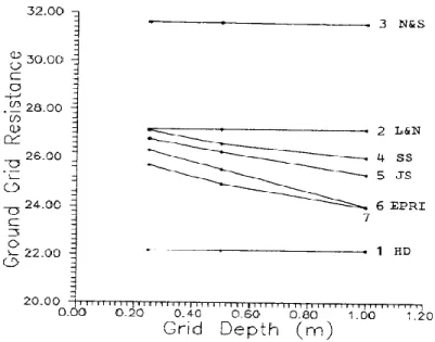
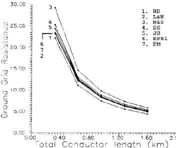
In fig.1 grounding grid resistance versus grid depth and in fig.2 grounding grid resistance versus conductor length has been shown. In fig. 3 grounding grid resistance versus number of meshes and in fig.4 grounding grid resistance versus wire diameter has been shown. From these four figures it is clear that grounding grid resistance is affected by grid depth, conductor length, number of meshes and wire diameter. In all the four figures curve 1 for Dwight formula (HD), curve 2 for Laurent and Niemann formula (L&N), curve 3 for Nahman and Skuletich formula ( N & S ) , curve 4 for Schwartz formula (SS), curve 5 for Sverak formula (JS), curve 6 for EPRI method (EPRI), curve 7 for Chow and Salama formula(PM).
International Journal of Research in Engineering & Applied Sciences
Email:- [email protected], http://www.euroasiapub.org
35
Fig. 2 Grounding grid resistance versus conductor length
International Journal of Research in Engineering & Applied Sciences
Email:- [email protected], http://www.euroasiapub.org
36
Fig. 4 Grounding grid resistance versus wire diameter
VI. Conclusion
The various parameters like grid area, soil resistivity, conductor length, depth of the buried grid, number of meshes and diameter of the grid conductor play an extremely vital role in the calculation of substation grounding grid resistance. Therefore, these parameters should be observed and measured seriously, so that substation grounding grid resistance can be calculated accurately.
References
[1] F. Dawalibi, and D. Mukhedkar, 1979, Parametric Analysis of Grounding Grid, IEEE Transactions on Power Apparatus and Systems, Vol.PAS-98, No.5 , pp.1659-1668
[2] F. Dawalibi, and J. Ma, 1994, Behaviour of Grounding Systems in Multilayer Soils: A Parametric Analysis, IEEE Transactions on Power Delivery, Vol. 9, No. 1, pp. 334-342.
[3] E. B. Joy, and R. E. Wilson, 1986, Accuracy Study of the Ground Grid Analysis Algorithm , IEEE Transactions on Power Delivery, Vol. 1, No. 3, pp. 97-103.
[4] J. Lazara, and N. Barbeito, 1990, Simplified Two Layer Model Substation Ground Grid Design Methodology, IEEE Transactions on Power Delivery, Vol. 5, No. 4, pp.1741-1750.
[5] B. Thapar, V. Ferez, A. Balakrishnan, and D. A. Blank, 1991, Evaluation of Ground Resistance of a Grounding Grid of any Shape”, IEEE Transactions on Power Delivery, Vol. 6, No. 2, pp 640-645. [6] H.B. Dwight, 1936, Calculations of Resistances to Ground, AIEE Transactions, pp.1319-1328. [7] IEEE Std. 80-2000, 2000, IEEE Guide for Safety in A.C Substation Grounding, Institute of
Electrical and Electronic Engineers, New York.
[8] J. Nohman, and S. Skuletich, 1980, Irregularity Correction Factors for Mesh and Step Voltages of Grounding Grids, IEEE Transactions on Power Apparatus and Systems, vol. PAS-99, No.1, pp. 174-180.
[9] S. J. Schwartz, 1954, Analytical Expression for Resistance of Grounding Systems, AIEE Transactions, vol. 73, Part 111-B, pp. 1011-1016.
[10] J. G. Sverak, 1976, Optimized Grounding Grid Design Using Variable Spacing
Technique, IEEE Transactions on Power Apparatus and Systems, vol. PAS-95, pp. 362 - 374.
[11 J.G. Sverak, 1984, Simplified Analysis of Electrical Gradients Above a Ground Grid: PartI - how Good is the Present IEEE Method?", IEEE Transactions on Power Apparatus and Systems, vol. PAS-103, pp. 7-25.
International Journal of Research in Engineering & Applied Sciences
Email:- [email protected], http://www.euroasiapub.org
37
volume 1: Design Methodology and Tests", EPRI EL-2682.[13] Y.L.Chow, and M.M.A.Salama, 1994, A Simplified Method for Calculating the
Substation Grounding Grid Resistance”, IEEE Transactions on Power Delivery, Vol. 9, No. 2, pp. 736-742.
[14] F. P. Dawalibi , and D. Mukhedkar, 1975, Optimum Design of Substation Grounding in Two-Layer Earth Structure - Part I, Analytical study”, IEEE Trans. PAS, vol.94, No.2, pp.252-261.