1
Cumulating Project for the Cal Poly Engineering IV Building
Kai Liu
Spring 2020
2
Statement of Disclaimer
This project report is a result of a class assignment; it has been graded and accepted as fulfillment of the course requirements. Acceptance of this report in fulfillment of the course requirements does not imply technical accuracy or reliability. Any use of information in this report is done at the risk of the user. These risks may include, but may not be limited to, catastrophic failure of the device or infringement of patent or copyright laws. California Polytechnic State University at San Luis Obispo and its staff cannot be held liable for any use or misuse of the project.
3
Table of Contents
Statement of Disclaimer ... 2
Abstract ... 6
Building Overview ... 7
Applicable Codes and Standards ... 8
Means of Egress Analysis ... 9
Occupancy Classification and Capacity ... 9
Travel Distance ... 11
Dead-End Corridors ... 13
Exit Sign ... 13
Minimum Number of Exits ... 13
Exit Separation... 14
Interior Finish ... 14
Summary of Prescriptive Egress Analysis ... 15
Structural Analysis ... 15
Fire Resistance Analysis ... 15
Construction Materials ... 15
Height Limitation Analysis ... 16
Area Limitation Analysis ... 16
Fire Separation ... 17
Summary of Prescriptive Structural Analysis ... 18
Fire Alarm Design Analysis ... 18
Identification of the Type of Fire Alarm System ... 18
Operating Characteristics of Fire Alarm System ... 19
Identification of the Model and Location of FACP ... 19
Identification of The Type and Location of Fire Detection Devices ... 20
Smoke Detector ... 21
Heat Detector ... 21
Duct Smoke Detector ... 21
Manual Pull Station ... 22
Location, Spacing and Placement of Fire Detection Devices ... 22
General ... 22
4
Heat Detectors ... 24
Duct Smoke Detectors ... 25
Fire Detector Response Analysis ... 25
General ... 25
Fire Scenario ... 25
Sprinkler Activation Time ... 26
Smoke Detector Activation Time ... 27
Fire Alarm System Types and Requirements ... 28
Identification of The Type and Location of Fire Notification Devices ... 28
General ... 28
Visible Alarm Notification Appliances ... 28
Audible Alarm Notification Appliances ... 30
Secondary Power Supply ... 31
System Commissioning and Inspection, Testing, and Maintenance... 33
Conclusion ... 34
Sprinkler System Analysis ... 34
Type of Water-Based Fire Suppression System ... 34
Water Supply Identification and Characterization ... 35
Occupancy Classification ... 36
System Risers, Branch Lines, and Sprinklers ... 36
Sprinkler System Calculations ... 38
Conclusion ... 40
Performance-Based Design Analysis ... 40
Performance-Based Design Goals ... 40
Tenability Criteria ... 41
Required Safe Evacuation Time ... 42
Pre-Movement Time ... 42
Hand Calculations Assumption ... 43
Design Fire ... 44
Design Fire 1 – Office Fire ... 44
FDS Model ... 45
FDS Results ... 46
5
Conclusion ... 48
Design Fire 2 – Atrium Fire ... 48
FDS Model ... 51
FDS Results ... 52
RSET Hand Calculation ... 54
Conclusion ... 57
Design Fire 3 – ME lab ... 57
FDS Model ... 59
FDS Result ... 60
Hand Calculation ... 61
ASET vs. RSET Summary ... 63
Conclusion ... 63
Reference ... 64
Appendix A – Occupancy Load ... 65
Appendix B – Exit Signs ... 65
Appendix C – Color Code Floor Plan ... 68
Appendix D – Sequence of Operation ... 71
Appendix E – Riser Diagram ... 72
Appendix F – Fire Alarm Floor Plan... 73
Appendix G – Hydraulic ... 79
Appendix H – Supply and Demand Curve ... 83
Appendix I – Sample Hydraulic Calculation ... 84
Abstract
This report analyzes the fire protection systems of Engineering IV building at California Polytechnic State University, San Luis Obispo. It is a cumulative project of the Fire Protection Engineering Program at Cal Poly. The report consists of a prescriptive analysis and a performance-based design analysis. The building contains dry laboratories, classrooms, offices, and administrative spaces. The building is a three-story structure. There is an atrium that connects the first floor to the third floor. However, the building has a horizontal enclosure to separate the connection between the second floor and the third floor.
The prescriptive analysis is based on the code standards and regulations, which includes five subsections: means of egress analysis, structure analysis, fire alarm analysis, and sprinkler system analysis. The means of egress analysis section determines the occupancy load of each floor, occupancy capacity based on the door/stair width factor, common path, travel distance, and dead-end corridors. The structural analysis determines height limitations, number of story limitations, and area limitations based on the construction type of this building. The fire alarm analysis discusses detection devices application, notification devices application, and battery calculations for the system. The sprinkler system analysis discusses water source information, water demand curve, and design area. Overall, the Engineering IV building meets the code requirements and standard regulations.
The performance-based design establishes a computational fire dynamic simulation (FDS) to calculate the time to reach untenable conditions based on the assumed tenability criteria (smoke density, visibility, the temperature at 6 feet above the walking surface). The tenability criteria are referred from SFPE Handbook 5th edition. Pyrosim is utilized in the analysis to present a visual friendly output result and to determine the available safe egress time based on assumptions. Required safe egress time (RSET) is determined by an evacuation model (hand calculation) and the results are compared to ASET. Three design fire scenarios are selected in this report based on recommendations of NFPA 101, Chapter 5. The first design fire scenario is a typical office catching on fire. The consequence of the office fire is smoke spreading to a corridor which may cause occupants to get stuck in a corridor. The ASET for this design fire scenario is 385 seconds, which is greater than RSET. The second fire scenario is selected in the atrium. Smoke spread into a large open space may delay the time to detect the fire. As a result, it will raise the risk for occupants to evacuate the building within a safe time. The result shows that ASET is 355 seconds and RSET is 343 seconds. The last design fire scenario is in a lab with a large fuel load. In this report, it discusses the possibility of people getting stuck in the compartment and corridor. Based on the assumptions, the result indicates that ASET is greater than RSET. Therefore, all three design fire scenarios proves that the fire protection system design in this building is adequate for occupancy to evacuate before the time reaches untenable conditions. In one of the design fires, ASET is only slightly greater RSET and the safety factor is close to 1, which may challenge occupant’s life safety. But Stair 3 in the atrium may be used for means of egress at the beginning of the fire. Even though it is not designed for evacuation, it can decrease overall evacuation time by avoiding queuing on the second floor.
7
Building Overview
Engineering Building IV is a new building at Cal Poly, San Luis Obispo, located on the northwest edge of the main campus. It contains dry laboratories, classrooms, offices and administrative space. The total area of this building is 104,631 SF.
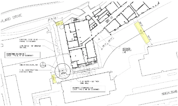
The new construction of a three-story teaching and research laboratory is built with two elevators and three exterior stairways and one interior stairway. The building type is Type II – F.R. in the Uniform Building Code, which is equivalent to Type I-B in International Building Code or California Building Code. In the report, all the analysis is based on Type I-B construction type. The building is constructed of steel brace frames, concrete-filled metal decks. The exterior wall is constructed of steel STUD frame walls faced with fiber-reinforced cementitious panel and metal panel siding. The roof is a modified bituminous membrane roof on rigid insulation. The main occupancy types are B occupancy and A-3 occupancy. Figures 1 to Figures 3 are the color-coded floor plan for each floor.
Figure 1. First Floor Building Layout
8
Figure 3. Third Floor Building Layout
Even though Engineering IV Building is a three-story building, it has a two-story atrium. To save cost, this building is not required to have a smoke control system. Therefore, the third floor is separated by horizontal closures as Figure 4 shows below. As a result, if a fire ignited on the first-floor atrium, it could quickly affect the tenability of the second floor. The report includes two main sections: the prescriptive analysis and performance-based design. Under the prescriptive analysis, there are five subsections: means of egress requirements, structural analysis, smoke control requirements, fire alarm requirements, and sprinkler system requirements. The performance-based design includes the analysis of three fire scenarios and comparison between available safe egress time (ASET) and required safe egress time (RSET).
Figure 4. Horizontal closure between the second floor and third floor.
Applicable Codes and Standards
The following codes and standards are referenced throughout this design
9
The following is a partial list of applicable standards throughout this design
• NFPA 13 Automatic Sprinkler System – 2019 Edition • NFPA 72 National Fire Alarm Code – 2019 Edition • NFPA 92 Smoke Control System – 2018 Edition. • NFPA 101 Life Safety Code – 2018 Edition
The Engineering IV building was designed based on 2001 edition codes and standards. But the project is referenced from the newer version to verify if the building is still qualified to meet current code requirements.
Means of Egress Analysis
Occupancy Classification and Capacity
According to CBC 2016, the Engineering IV building is classified into two sections: A-3 and B. If the occupancy space is less than 50 people, it defined as type B occupancy. Otherwise, it is classified as A-3 occupancy. Based on the use, area, and occupancy factor of spaces, the occupancy load is provided in Table 1 to Table 3.
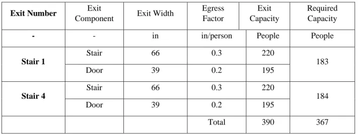
According to California Building Code (CBC) Section 1005.3.1, the capacity, in inches, of means of egress stairways shall be calculated by multiplying the occupant load served by such stairways by a means of egress capacity factor of 0.3 inches (7.6 mm) per occupant. Where stairways serve more than one story, only the occupant load of each story considered individually shall be used in calculating the required capacity of the stairways serving that story. And the egress capacity factor of 0.2 inches per occupant for doors as it states in Section 1005.3.2. Overview of the exits plan of the first floor, there are 5 main exit doors. But 11 classrooms or labs have exit doors open to the outside for each space to evacuate. Thus, the first floor can provide total occupancy capacity (5 main exits) is 2520 people. The second floor has three exit stairs and the third floor has two exit stairs. Stair 3 on the second and third floors cannot be used for means of egress due to its connection with the atrium. The provided occupancy capacity for these two floors is 540 people and 390 people. Details exit capacity calculation can be found from Table 1 to Table 3. All floors provide adequate exit capacity based on the code requirements.
Table 1. First floor exit summary
Exit Number Exit
Component
Exit
Width Egress Factor
Exit
Capacity Occupant Load
- - in in/person People People
Lobby Exit Door 216 0.2 1080 136
Room 101 Exit Door 72 0.2 360 18
Room 102-1 Exit Door 32 0.2 160 36
Room 102-2 Exit Door 32 0.2 160 35
Room 103 Ext Door 84 0.2 420 8
West Corridor Exit Door 72 0.2 360 73
10
Room 105-1 Exit Door 32 0.2 160 25
Room 105-2 Exit Door 32 0.2 160 25
Room 106 Exit Door 32 0.2 160 78
North Corridor
Exit Door 72 0.2 360 73
East Corridor Exit Door 72 0.2 360 80
Room 130 Exit Door 280 0.2 1400 29
South Corridor
Exit Door 72 0.2 360 73
Room 135 Exit Door 72 0.2 360 12
Room 136 Exit Door 72 0.2 360 15
Total 5960 735
Table 2. Second floor exit summary
Exit Number Exit
Component Exit Width
Egress Factor
Exit Capacity
Required Capacity
- - in in/person People People
Stair 1
Stair 66 0.3 220
174
Door 36 0.2 180
Stair 2
Stair 66 0.3 220
173
Door 36 0.2 180
Stair 4
Stair 66 0.3 220
174
Door 36 0.2 180
11
Table 3. Third floor exit summary
Exit Number Exit
Component Exit Width
Egress Factor
Exit Capacity
Required Capacity
- - in in/person People People
Stair 1
Stair 66 0.3 220
183
Door 39 0.2 195
Stair 4
Stair 66 0.3 220
184
Door 39 0.2 195
Total 390 367
Travel Distance
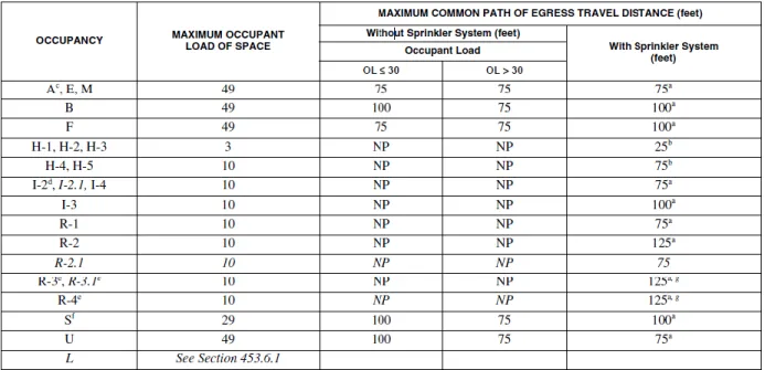
According to CBC Section 404.9.1, where required access to the exits is not through the atrium, exit access travel distance shall comply with Section 1017. In Table 1017.2 (Table 5), it provides the maximum allowable travel distance based on different occupancy. The building is mainly B occupancy and A-3 occupancy. Thus, the maximum travel distance with the sprinkler system is 250 feet for B and 300 feet for A-3.
Table 5. Exit access travel distance
12
Figure 5. Location of maximum travel distance
California Building Code requires the maximum common path of egress travel distance for A occupancy is 75 feet with a sprinkler system and B occupancy is 100 feet with a sprinkler system.
Table 6. The maximum common path of egress travel distance
13
Figure 6. Maximum common path in Engineering IV building.
Dead-End Corridors
CBC Section 1020.4 states that the length of dead-end corridors limitation is 50 feet with automatic sprinkler system. As shown in Figure 7 below, the maximum length of dead-end corridors is about 34 feet located on the second floor.
Figure 7. Maximum dead-end corridors in Engineering IV building.
Exit Sign
CBC Section 1031.1 states that exit and exit access doors shall be marked by an approved exit sign readily visible from any direction of egress travel. The path of egress travel to exits and within exits shall be marked by readily visible exit signs to indicate the direction of egress travel in cases where the exit or the path of egress travel is not immediately visible to the occupants. Intervening means of egress doors within exits shall be marked by exit signs. Exit signs shall be placed within 100 feet between from the nearest visible exit sign in an exit access corridor or exit passageway. Appendix B provides the locations of exit throughout the building. Therefore, the layout of exit signs meets the code requirements.
Minimum Number of Exits
14
501 – 1,000, the minimum number of exits is 3; occupant load is greater than 1,000, the minimum number of exits is 4. The first floor in Engineering IV building requires 3 exits, and it provides 5 exits; The second floor requires 3 exits, and it provides 3 exits; The third floor requires 2 exits, and it provides 2 exits. Therefore, Engineering IV building meets these requirements.
Table 7. Minimum number of exits requirements
Exit Separation
CBC Section 1007.1.1 Exceptions 2 also requires exits separation shall be placed a distance apart equal to not less than one-third of the length of the maximum overall diagonal dimension of the building or area to be served measured in a straight line between them. Engineering IV building has provided adequate exit separation distance. An example is shown in Figure 8.
Figure 8. Exits separation
Interior Finish
15
Table 8. Interior wall and ceiling finish requirements
Summary of Prescriptive Egress Analysis
The section above discusses egress designs present within Engineering IV building. The discussion includes exit capacity, travel distance, dead-ends corridors, exit sign, minimum of exits, exit separation and interior finish. All designs are referenced based on current California Building Code and Life Safe Code in this report. The designs are adequate to meet the code requirements. In the next section, prescriptive structural analysis will be outlined.
Structural Analysis
Fire Resistance Analysis
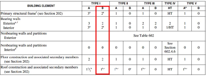
Engineering IV building elements that listed in Table 9 is made of noncombustible material. In addition, this building has a height of 51 ft, 3 stories and area per story of 42,400 ft2. Based on the information provides above, Type I-B construction type fulfills the code requirement per 2016 CBC. But according to the actual building height, number of stories and area per story, Type II-A construction type can also be considered conservative.
The structural elements in Type I-B buildings shall be made of steel, iron, concrete or masonry. Table 9 provides the requirement of fire resistance for this construction type, which is taken from 2016 CBC Table 601.
Table 9. Fire resistance rating requirements for building elements (Hours)
Construction Materials
16
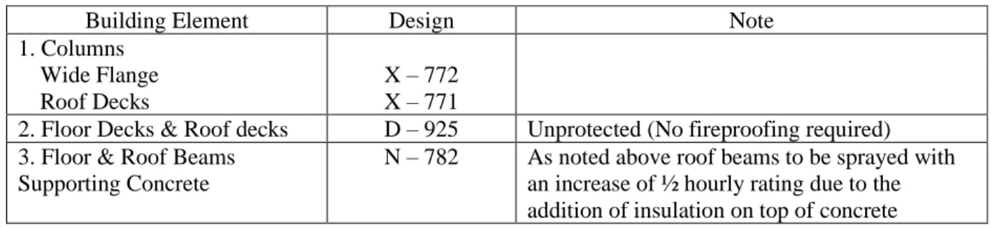
Table 10. Construction materials
Building Element Design Note
1. Columns Wide Flange Roof Decks
X – 772 X – 771
2. Floor Decks & Roof decks D – 925 Unprotected (No fireproofing required) 3. Floor & Roof Beams
Supporting Concrete
N – 782 As noted above roof beams to be sprayed with an increase of ½ hourly rating due to the addition of insulation on top of concrete
Height Limitation Analysis
Engineer IV Building is a three-story building. According to CBC 2016 Table 504.3 (Table 11), the allowable height is 180 ft. The actual height is 51 ft such that meets the requirement by code.
Table 11. Allowable building height
The A-3 occupancy is allowed 11 stories; however, Engineering IV Building is installed with an automatic sprinkler system. As a result, increasing one floor is allowed by code. Therefore, 12 stories allowed versus 3 stories actual. The B occupancy is allowed 12 stories versus 3 stories actually. Thus, the allowable stories meet the requirement by code (Table 12).
Table 12. The allowable number of stories
Area Limitation Analysis
17
Table 13. Allowable area of each floor.
To display a clearer contrast, Table 14 provides a comparison between code requirements and actual situation of building height, number of stories and area per story.
Table 14. Comparison between code requirements and provided building height, number of stories and area per story
Allowable Actual
Height 180 feet 51 feet
Stories 12 (B and A-3) 3
Area per Story UL 42,400 sf
Fire Separation
CBC states that fire separation distance requires the exterior walls and openings in exterior walls shall comply with Tables 601 and 602 (Table 15). The distance shall be measured from the building face to one of the following at right angles from the face of the wall:
1. The closest interior lot line;
2. To the centerline of a street, an alley or public way; or 3. To an imaginary line between two buildings on the lot
18
Figure 9. Fire distance between Engineering IV building and other buildings
Table 15. Fire-Resistance Rating Requirements
Summary of Prescriptive Structural Analysis
The structural analysis outlines the fire protection features within Engineering IV building. The prescriptive analysis is focused on the code requirements of 2016 CBC. Based on the construction type, all the structural materials meet the code requirements. In addition, the allowable building height, area and fire separation do not conflict with the current code requirements. The following section will analyze the prescriptive fire alarm design.
Fire Alarm Design Analysis
Identification of the Type of Fire Alarm System
A completed fire alarm system floor plan of each floor is attached in Appendix C. Engineering IV building is installed with a conventional fire alarm system which is fully addressable. The fully addressable fire alarm system provides details on the individual detectors. In this system, various form of detection and notification devices are connected to one fire alarm control panel (FACP). These devices are monitored and protecting the building 24/7.
19
Operating Characteristics of Fire Alarm System
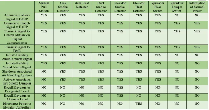
In Appendix D (also see Table 16), the table of a sequence of operation illustrates the initiating devices correspond with the fire alarm protection system.
Table 16. Sequence of Operation
When manual pull station, area smoke detector, area heat detector, duct smoke detector, elevator smoke detector, elevator heat detector and sprinkler flow switch activate, they will annunciate alarm and trouble conditions at the fire alarm control panel; transmit a signal to central station and BMS; initiate building audible and visual alarm signal.
All types of smoke detector and heat detector and sprinkler flow switch will shut down associated air handling systems and fire smoke dampers.
When elevator smoke detector activates, it will recall elevators to a designated or alternate level. The elevator heat detector will disconnect power to elevator controllers.
Sprinkler tamper switch and interruption of normal power annunciate trouble signal at FACP and transmit a signal to central station and BMS.
Identification of the Model and Location of FACP
20
Figure 10. Notifier NFS-60 Fire Alarm Control Panel.
The location of the FACP is shown in Figure 11. It is located on the first floor, Room 109 electrical room.
Figure 11. Location of FACP
Identification of The Type and Location of Fire Detection Devices
21
Smoke Detector
The smoke detectors installed in the Engineering IV building are Notifier FSP-851 (CSFM #7150-0028:199) model as shown in Figure 12. They are intelligent, photoelectric detectors including point ID capability that enables each detector address to be set with rotary address switches to provide exact detector locations. The listed spacing is 30 feet. There is a total of 243 units installed in the building. They are equipped in almost every classroom, lab, office and corridor.
Figure 12. Notifier FSP-851 Smoke Detector
Heat Detector
The heat detectors installed in the Engineering IV building are Notifier FST-851 (CSFM #7270-0028:196) model as shown in Figure 13. They are intelligent, 135°F fixed temperature detectors including point ID capability that enables each detector address to be set with rotary address switches to provide exact detector locations. The listed spacing is 30 feet. There is a total of 9 units installed in the building. They are equipped in Room 103, Room 103A, Room 108, Room 111, Room 112A, Room 114, Room 216, Room 316, and Elevator #2. Most of them are protecting the storage space or mechanical equipment.
Figure 13. Notifier FST-851 Heat Detector.
Duct Smoke Detector
22
Figure 14. Notifier FSD-751P Duct Smoke Detector
Manual Pull Station
The manual pull station installed in Engineering IV building is Notifier NBG-12LX models. They are intelligent. There is a total of 22 units equipped through the building. 16 of them are installed on the first floor near the exit doors. 3 of them are installed on the second floor near to the exit stairs. And 3 of them are installed on the third floor near the exits access to the exit stairs.
Location, Spacing and Placement of Fire Detection Devices
General
In this section, I will determine if the location, spacing and placement of fire detection devices installed in Engineering IV building comply with the code requirement of NFPA 72. The automatic sprinkler will be discussed in sprinkler system analysis.
Smoke Detectors
23
Figure 15. Main Corridor
The locations of smoke detectors also need to consider the effect of ambient temperature, relative humidity, and air velocity. According to NFPA 72, 17.7.1.8, unless specifically designed and listed for the expected conditions, smoke detectors shall not be installed if any of the following ambient conditions exist:
(1) Temperature below 32°F (0°C). (2) Temperature above 100°F (0°C). (3) Relative humidity above 93 percent.
(4) Air velocity greater than 300 ft/min (1.5 m/sec).
The code also states in section 17.1.10, the location of smoke detectors shall be based on evaluation of potential ambient sources of smoke, moisture, dust or fumes and electrical or mechanical influences, to minimize nuisance alarms. It explains why Room 103A (welding lab) and Room 111 (pump room) do not have smoke detectors.
In Engineering IV building, the most possible location airflow that can affect the sensibility of smoke detectors is where air vents for the HVAC system are installed. By rough measurement, the smoke detectors are placed several feet away from the air vents. Thus, the influence made by airflow is negligible.
24
Figure 16. The unprotected area by smoke detectors
To explain why the corridor area is not protected, the reasonable assumption is that a large HVAC vent runs along the ceiling in the corridor. There is no space for the smoke detectors to be installed on the ceiling. But sprinklers are presented in this area with 8’ to 15’ spacing. Another location without smoke detector is the atrium. The atrium is open to the second floor is about 30 feet high. It does not comply with the code requirements. There are some solutions to this situation. First, no ignitable materials are placed in the atrium, except couches. But the couches are protected by sprinklers and smoke detectors which are mounted on the extended portion on the second floor. Figure 17 shows what it looks like. The second solution is placing sprinklers on the second-floor ceiling with 10’ spacing.
Figure 17. Location of sprinklers, smoke detectors and furniture
Heat Detectors
25
listed spacing, measured at right angles from all walls or partitions extending upward to within the top 15 percent of the ceiling height. And all points on the ceiling shall have a detector within a distance equal to or less than 0.7 times the listed spacing. The spacing shall be reduced based on ceiling height. More details are shown in Table 17. Engineering IV building only equipped a few heat detectors. All of them are mounted on a smooth ceiling in rooms. The ceiling height of each floor is 15 feet. Taking account of spacing reduction, the heat detectors are still able to cover the required areas. Therefore, device coverage is adequate.
Table 17. Heat detector spacing reduction based on ceiling height
Duct Smoke Detectors
According to NFPA 17.7.5.5.2, and 17.7.5.5.3, duct smoke detectors should be rigidly mounted within the duct to obtain a representative sample of the airstream. The duct smoke detectors are placed within the duct which connects to the air handling units on the third floor. Therefore, device placement meets the code requirements.
Fire Detector Response Analysis
General
In this section, an appropriate fire scenario is identified and justified. The expected response characteristics of the fire detection devices installed in the building are calculated. It includes hand calculations and FDS results.
Fire Scenario
The selected fire scenario is taking place in Room 122, office room, located on the east end of the first floor. Office 122 is a very typical office room in dimensions. In this compartment, the main source of fuel will be a computer workstation consisting of a computer desk and a bookcase. Each is constructed with 5/8” thick particleboard covered with simulated wood, plastic laminate. The desk was loaded with 99 lb. of paper materials and the bookcase was loaded with 160 lb. of paper materials. This is a very typical office layout. Thus, it would be enough to represent the compartment fuel load. The dimension of the office is 3.5m x 3.2m x 4.6m.
26
Figure 18. HRR curve of the office compartment. The maximum HRR is 1800 kW.
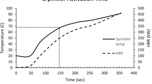
Sprinkler Activation Time
To calculate the sprinkler activation time, the input parameters need to be determined which is shown in Table 18. The sprinkler is placed on the ceiling height of 4.5 meters above the fire and the radial distance is 1 m away from the center of the fire. Assume an ambient temperature is 20 °C and a sprinkler activation temperature is 68 °C. Based on the manufacturer’s specification, the sprinkler RTI is 50 (ms)1/2.
Table 18. Input parameters for sprinkler activation time
INPUT PARAMETERS
Ceiling height (H)
4.5
m
Radial distance (R)
1
m
Ambient temperature (T0)
20
C
Actuation temperature (Td)
68
C
Response time index (RTI)
50
(ms)
1/2Heat release rate (kW)
Database
The method used to determine the sprinkler activation time is Alpert ceiling jet correlation:
𝐶𝑒𝑖𝑙𝑖𝑛𝑔 𝑡𝑒𝑚𝑝𝑒𝑟𝑎𝑡𝑢𝑟𝑒:
𝑇𝑗− 𝑇∞ = 5.38
𝐻 (
𝑄̇ 𝑟)
2 3
,𝑟
𝐻> 0.18 𝐶𝑒𝑖𝑙𝑖𝑛𝑔 𝑠𝑚𝑜𝑘𝑒 𝑣𝑒𝑙𝑜𝑐𝑖𝑡𝑦:
𝑢𝑗= 0.195 ( 𝑄̇13𝐻
1 3 𝑟56
) ,𝑟
𝐻 > 0.15 0
200 400 600 800 1000 1200 1400 1600 1800 2000
0 500 1000 1500 2000 2500 3000
H
eat
Rel
ease
Rat
e (k
W)
Time (sec)
27
𝐷𝑒𝑡𝑒𝑐𝑡𝑜𝑟 𝑡𝑒𝑚𝑝𝑒𝑟𝑎𝑡𝑢𝑟𝑒:
𝑇𝑑𝑖+1=√𝑢𝑗
𝑅𝑇𝐼(𝑇𝑗− 𝑇𝑑 𝑖) + 𝑇
𝑑𝑖
The result indicates that the sprinkler activates at 146 seconds, which shows in Figure 19. When a sprinkler activates, the HRR is about 250 kW.
Figure 19. Sprinkler activation time and fire size at that time.
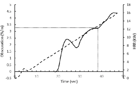
Smoke Detector Activation Time
The method to determine the smoke detector activation time is different than the sprinkler activation calculation. Instead of using Alpert ceiling jet correlation, FDS is used in this analysis. The smoke detector is placed on the ceiling height of 4.4 meters above the fire and the radial distance is 2 m away from the center of the fire. Assume an ambient temperature is 20 °C and a smoke detector activation obscuration threshold is 3.28 %/m. Based on the graph shown in Figure 20, the smoke detector activates at about 38 seconds. At that time, the HRR is about 13 kW.
0 50 100 150 200 250 300 350 400 450 500
0 10 20 30 40 50 60 70 80 90 100
0 50 100 150 200 250 300 350 400
H
RR (kW
)
Te
m
p
era
tu
re
(C
)
Time (sec)
Srpinkler Activation Time
Sprinkler temp
28
Figure 20. Smoke detector activation time and the fire size at that time.
Fire Alarm System Types and Requirements
In this section, the type of fire alarm system installed in the Engineering IV building is described along with the requirements for the disposition of alarm, supervisory and trouble signals.
The type and location of the fire alarm control panel are discussed in Section 4. Details of wiring connection are attached in Appendix F. There are four power supplies are connected with the FACP to provide adequate voltage to support all devices. The fire alarm annunciator is installed on the wall of first-floor atrium, against the main entrance. The panel is also connected to off-site monitoring via dual phone lines.
The code requirement of the disposition of alarm, supervisory and trouble signals shall refer to NFPA 72, section 10.11 alarm signals; section 10.12 fire alarm notification appliance deactivation; section 10.14 supervisory signals; and section 10.15 trouble signals. The code illustrates the actuation of alarm notification appliances or emergency voice communications, emergency control function interface devices, and annunciation at the protected premises shall occur within 10 seconds after the activation of an initiating device. It also stipulates the supervisory signals and trouble signals activation and deactivation conditions. Furthermore, the code requires that an audible trouble signal shall be permitted to be intermittent provided its sounds at least once every 10 seconds, with a minimum duration of ½ second. Last, to restore the panel to normal condition, it requires all supervisory devices are reset and trouble signal are cleared.
Identification of The Type and Location of Fire Notification Devices
General
In this section, the types, locations and spacings of alarm notification devices installed in Engineering IV building will be discussed. The building contains two types of notification devices, visible alarm notification devices and audible alarm notification devices.
Visible Alarm Notification Appliances
29
According to Section 18.5.5.1, wall-mounted appliances shall be mounted such that the entire lens is not less than 80 in. and not greater than 96 in. above the finished floor or at the mounting height specified using the performance-based alternative of 18.5.5.7. Engineering IV building fire alarm floor plan provides information of mounting detail, as shown in Figure 21. The horn strobes or strobes installed in the building are mounted at least 80 in. above the finish floor, which meets the code requirements.
Figure 21. Horn strobes and strobes mounting details.
The spacing for wall-mounted visual notification appliances shall follow Table 18.5.5.5.1 (a) (Table 19).
Table 19. Room spacing for wall-mounted visual notification appliances
30
Large design rooms or labs, such as Room 136, CEEN-HYDRAULICS LAB, are equipped with 110cd strobes or horn strobes. The dimension of Room 136 is 35’ x 48’. The maximum allowable room size for an effective intensity of 110cd is 54’ x 54’. Therefore, those large design studios installed with 100cd strobes or horn strobes shall have enough area coverage.
Other, even larger rooms, are equipped with a combination of different effective intensity strobes. For example, Room 106 is installed with one 75cd (allowable room size 45’ x 45’) horn strobe and three 110cd (allowable room size 54’ x 54’) strobes, with approximately covers the total of 52’ x 82’.
Referring to Section 18.5.5.6, spacing in corridors requires the installation of visual notification appliances in corridors 20 ft or less in width shall be following the requirements of spacing in rooms (18.5.5.5) or spacing in corridors (18.5.5.6). In addition, the visual notification appliances shall be located not more than 15 ft from the end of the corridor with a separation not greater than 100 ft between appliances and shall be rated not less than 15 cd.
The Corridor 100 C starts from the western end with initially 8’ wide and runs towards to atrium. At the end of the eastern end, the corridor width increases to 20’. Other corridors in this building are approximately 8’. Therefore, the corridors follow the code requirements of spacing in corridors.
Corridor 100A is served by two 110cd horn strobes and two 15cd strobes. The distance between each strobes or horn strobe is 15’ to 50’ which is much less than the required 100’. Corridor 100A has extra area coverage because there are two corners in the middle of the corridor. As a result, visible light cannot travel from one end to another end without stopping. In this case, two 15cd strobes are installed in the corners to ensure the corridor is fully covered by the strobe. Refer to Figure 22 for the location of strobes installed in Corridor 100A.
Figure 22. Location of strobes in Corridor 100A
Corridor 100B is covered by only one 15cd horn strobe because the total length of the corridor is 34’. There are three 110cd horn strobes and one 75cd strobe installed in Corridor 100C. The maximum distance between each strobe is 80’. The corridors on the second floor and third floor have a similar layout. All of them meet the code requirements.
Audible Alarm Notification Appliances
31
NFPA 72, Section 18.4.4.1, the sound level shall be at least 15 dB above the average ambient sound level or 5 dB above the maximum sound level having a duration of at least 60 seconds, whichever is greater. Engineering IV building is a primary business use and educational use. According to Table A. 18.4.4, the average ambient sound level for business occupancies is 54 dB, for educational occupancies is 45 dBA. This building is primarily running for educational use, so it shall be conservative taking 45 dBA as the average ambient sound level. Thus, the minimum sound pressure level shall be 60 dBA. According to the datasheet provided by System Sensor, the horn strobe (P1224MCW) can provide 75 dBA within 16-33V.
Another factor that could affect the effective intensity is distance. Robert P. Schifiliti discussed in his article, Notification Appliances, in a wide-open space where the sound does not reflect off any surfaces (no reverberation), the SPL (sound pressure level) decreases by roughly 6 dB every time the distance from the source is doubled. For example, if an audible appliance mount on a wall has a rating of 90 dBA at 10 ft. When the distance is 20 ft. away from the appliance, the rating reduces to 84 dBA (Figure 23.)
Figure 23. Example of 6 dBA rule.
The 6-dBA rule is not only applicable for horizontal distance but also vertical distance. Engineering IV building has a height of 15 ft for each floor. The horn strobe can still provide a rating of 63 dBA at 30 ft in the two-story atrium (75 dBA at 10 ft).
Section 18.4.8 requires audible notification appliances install at the exit. According to Engineering IV building’s fire alarm floor plan, all main exits doors or stairs are equipped with one horn strobe. For instance, at the end of Corridor 100A, a 110cd horn strobe is installed; at the Stair #1 exit on the second floor, a 15cd horn strobe is installed. Therefore, sound pressure level design for this building are conservative.
Secondary Power Supply
In this section, the secondary power supply requirements for the fire alarm system will be determined.
According to 10.6.6.2, the secondary power supply shall automatically provide power to the supervising station facility and equipment within 60 seconds whenever the primary power supply voltage is insufficient for required system operation. Section 10.6.7.2 states that the secondary power supply shall provide a minimum of 24 hours of operation capacity under quiescent load and shall be capable of operating all alarm notification appliances for 5 minutes. And the battery calculation shall include a minimum 20 percent safety margin.
32
In the Engineering IV building fire alarm floor plan, it does not provide any battery calculations. Instead, Notifier Battery Calculation is used to verify the capacity of the secondary power supply. The results are shown in Figure 24 to Figure 28. The secondary load requirements are below the provided power supply capacity. The battery calculations were found to be adequate and appropriate for this application.
Figure 24. NFS-60 battery calculation
Figure 25. FCPS1 ACPS-2406 battery calculation
33
Figure 27. FCPS3 ACPS-2406 battery calculation
Figure 28. FCPS4 ACPS-2406 battery calculation
System Commissioning and Inspection, Testing, and Maintenance
Before the fire alarm system is ready to be installed and tested, the required documentation shall be approved by the authority having jurisdiction (AHJ) and system contractor. The documentation shall include as-built drawing, sequence of operations matrix, symbols legend & bill of material, battery calculations, notification appliance circuit voltage drop calculations, point-to-point connection, riser diagram, wiring details, equipment submittals, operational manuals and manufacturer’s proper testing and maintenance requirements. After the installation is completed, the system also needs to pass the testing and inspection by AHJ. NFPA 72, Table 14.3.1 provides instruction for visual inspection in detail. And Table 14.4.3.2 provides testing instructions in detail. It includes the components that need to be tested, periodic frequency and methods to test the system.
The checklist of visual inspection summary for Engineering IV building is provided as below:
(1). Control equipment:
a. Fire alarm systems monitored for alarm
b. Fire alarm systems unmonitored for alarm, supervisory, and trouble signals
(2). Batteries:
34
b. primary (dry cell) other than those used in low-power radio (wireless) systems
(3). Remote annunciators
(4). Notification appliance circuit power extenders
(5). Remote power supplies
(6). Initiating devices
a. Duct detectors
b. electromechanical releasing devices
c. Fire extinguishing system (s)
d. manual fire alarm box
e. smoke detectors
f. supervisory signal devices
g. waterflow devices
(7). Alarm control interface and emergency control function interface
(8). Notification appliances
a. audible appliances
b. visual appliances
(9). Exit marking audible notification appliances
(10). Supervising station alarm systems – receivers
a. signal receipt
b. receivers
To ensure the fire alarm system running properly over time, it requires the system to be carefully maintained. The owner can refer to the checklist above.
Conclusion
The section presents a prescriptive analysis of the Engineering IV building fire alarm system. It has been found the building adequately meets NFPA 72 requirements for initiating devices and notification appliances. The report also attaches to material submittals in Appendix J as a reference. The following section will discuss sprinkler system.
Sprinkler System Analysis
Type of Water-Based Fire Suppression System
35
Figure 29. Basic Components of a Wet Pipe Sprinkler System
The wet pipe sprinkler system will be monitored by single monitor modules or double monitor modules. Once the pressure drops, it will send a signal to the Fire Alarm Control Unit to notice occupants for evacuation.
Water Supply Identification and Characterization
According to NFPA 13, Section 5.1.1, every automatic sprinkler system shall have at least one automatic water supply. The water supply of the Engineering IV Building is connected to the city water supply. The water source is located 175 ft away from the building in the south connected with an 8” main running water source. A control valve is connected between 6” feed line and 8” main. And there is a 6” double check valve assembly located in the south nearby the building. The locations are shown in Figure 30. The double-check valve and the control valve are connected by a 6” diameter line with a minimum depth of bury is 3’-0”. One OS&Y gate valve is connected with the 6” feed, monitored by a double monitor module. And an FDC is installed next by the OS&Y gate valve in the south of the building.
36
The water supply information is provided in Table 20.
Table 20. Water Supply from The City
Static Pressure (psi) Residual Pressure (psi) Water Flow (GPM)
80 65 1244
Fire department connection requires to be provided if none of the systems meet the requirements in NFPA 13, Section 16.12.2. Therefore, Engineering IV Building is required to provide fire department connection and shall be provided as described in Figure 31.
Figure 31. Fire Department Connection.
Occupancy Classification
The occupancy classification includes light hazard, ordinary hazard (Group 1), ordinary hazard (Group 2), extra hazard (Group 1), and extra hazard (Group 2). NFPA 13, Section 4.3.2 and 4.3.3 give the definition of light hazard and ordinary hazard (Group 1). The light hazard classification is defined as spaces with low quantity and combustibility of contents. The ordinary hazard classification is defined as spaces with moderate quantity and low combustibility of contents; stockpiles of contents with low combustibility that do not exceed 8 ft (2.4 m). Engineering IV Building shall be classified as a light hazard because most of the spaces are used for lecture and office, except BIOMED WET LAB located on the third floor shall be classified as an ordinary hazard (Group 1).
System Risers, Branch Lines, and Sprinklers
37
Figure 32. First-floor riser details
38
4” cross main is running through all floors. The branch lines connect to the cross main are mainly 1-1/4”. For some special cases, 1” branch lines are also installed in the building. Typically, upright sprinklers are connected to the branch lines. A sample of shop drawings is shown in Figure 34.
Figure 34. Engineering IV cross main and branch lines of sprinkler system shop drawing
Engineering IV building has installed a total of 920 sprinklers. The building is fully protected by the sprinkler system. There are five different types of sprinklers. Depending on the fire hazards and locations, different types of sprinklers have various applications. Table 21 shows the make and model, orifice, K-factor, head finish plate finish, activation temperature quantity of the sprinkler used in Engineering IV building.
Table 21. Summary of Sprinklers
Make and Model Orifice K-Factor Head
Finish
Activation
Temperature Quantity Reliable F1FR Upright on 1”
SPRIG / SIN# 3625
1/2” 5.6 Brass
155°F 242
Reliable F1FR Upright on 1” SPRIG / SIN# 3625
1/2” 5.6 Brass
200°F 28
Reliable G4A Concealed Pendent / SIN# 5415
1/2” 5.6 Brass
155°F 618
Reliable F1FR Horizontal Sidewall / SIN# 3635
1/2” 5.6 Brass
200°F 2
Tyco WS Vertical Pendant / SIN# TY3488
1/2” 5.6 Brass
155°F 30
Sprinkler System Calculations
39
classification rooms are greater than the reduced value. The larger design areas would be considered conservative since it could create a greater system demand. In addition, the supply and demand curve, attached in Attachment H (also shown in Figure 35), shows that the water source provides 1240 gpm at 65 psi (shown in Figure 30) and the hose stream requirement is 721 gpm. The most hydraulically isolated area of the building is located on the third floor and requires 210 gpm at 67.2 psi. Because, the water source supplies enough pressure and water flow at the most remote sprinkler, a fire pump is not required. Thus, the calculated system demand (pressure required, flow required) for all design areas meet the requirement. One sample hydraulic calculation for the hydraulically remote area on the first floor (Figure 37) is attached in Attachment I. The assumptions are made for the hydraulic calculation are the following: pipe is made of schedule 40 wet steel with a C-factor of 120, value for equivalent length is referenced from NFPA 13, density is 0.15 gpm/ft2 and a design operation of 130 ft2. Results of the sample calculation show that the required flow is 163.4 gpm and the require pressure is 49.7 psi. The safety margin of the pressure is 36%. Thus, the Engineering IV Building sprinkler system design is conservative. Attachment B includes all the design areas calculation.
40
Figure 36. Density/Area Curves.
Figure 37. Hydraulically remote area on the first floor.
Conclusion
Based on the analysis of Engineering IV Building hydraulic calculation above, it proves that the city water supply provides adequate water flow and pressure for each design area. Therefore, the sprinkler system meets the requirement of sprinkler system demand based on the code requirements. Considering the pipe size selection and cost, this is a good design for efficiency. To make it more efficient, I would recommend considering replacing the ductile iron pipe to plastic pipe, since the plastic pipe is a cheaper and low level of leaching and corrosion. In long term use, this is probably a better solution to make the system more efficient. The flowing section will analyze the performance-based design within the Cal Poly Engineering IV building.
Performance-Based Design Analysis
The following section of this report discusses the performance-based design for the Engineering IV building. Based on assumptions, there are three fire scenarios considered. These scenarios are considered as the highest fire risk or may cause the worst damage. They are evaluated by Fire Dynamics Simulation (FDS) and Pyrosim. In the next subsections, the goals, assumptions, methods, and results of analyzing the fire scenarios will be discussed.
Performance-Based Design Goals
41
available safe egress time (ASET) and required safe egress time (RSET). Comparing the results and finding out which one takes less time for evacuation (Figure 38). To determine the RSET, SFPE Handbook 5th edition provides recommendations for tenability criteria. Based on that, FDS could present the time to reach untenable conditions. Only if ASET is greater than RSET, the life safety system in Engineering IV building could be considered adequate.
Figure 38. ASET vs. RSET
Tenability Criteria
To determine if the time reaches untenable conditions, SFPE Handbook and Life Safety Code (LSC) present the recommendation for visibility, carbon monoxide, and temperature. SFPE Handbook Table 61.3 (Table 22) states that for occupants who are unfamiliar with the building layout, the smoke density cannot exceed 0.15 1/m and visibility cannot less 13 meters; for those who are familiar with the building layout, the code suggests that the smoke density cannot exceed 0.5 1/m and visibility cannot less than 4 meters at 6 feet above the walking surface or any occupied rooms. The temperature shall not exceed 60 °C at that level. The assumptions apply to all fire scenarios. In my design fires, the occupants have different familiarities to their egress plan. Design Fire 1 and Design Fire 3 are occupied with mostly students who are potentially considered as unfamiliar with the building geometry. But Design Fire 2 has only one exit and the occupants are professors who are considered to be familiar with the egress plan. Thus, in Design Fire 1 and Design Fire 2, the tenability criteria correspond to a visibility of 13 meters at 6 feet above the walking surface. And in Design Fire 2, the tenability criteria correspond to visibility of 4 meters.
42
Required Safe Evacuation Time
The evacuation time includes premovement time and travel time. This is the total time between notification of occupants that they need to move to a safe place and the time that the last occupant reaches that place.
Pre-Movement Time
To calculate RSET, it requires to determine the time for detection systems to actuate and initiate notification sequence, occupant’s reaction time and pre-evacuation. Time to notification appliance activates can be determined by FDS modeling results. When the smoke detector detects a fire, a signal will transmit to a fire control panel. Then a signal will be sent from the FACP to notification appliances. The transmitting time is considered negligible. Finally, the pre-evacuation varies for different fire scenarios based on different ages and genders. SFPE Chapter 64 Table 64.9 provides several experiments’ data for different educational occupancies. They cannot completely represent the occupant’s pre-evacuation time for Engineering IV building, but the mean data set is considered as a reasonable assumption to analyze it. There is a total of 25 experiment sets. The mean pre-evacuation time is 60 seconds as shown in Table 23 below.
Table 23. Mean Pre-Evacuation Time
Mean Pre-Evacuation Time for Educational Occupancies from Different Data Sets (sec)
Trial 1 10
Trial 2 17
Trial 3 20
Trial 4 20
Trial 5 24
Trial 6 25
Trial 7 27
Trial 8 29
Trial 9 32
Trial 10 38
Trial 11 39
Trial 12 39
Trial 13 42
Trial 14 43
Trial 15 52
Trial 16 52
43
Trial 18 56
Trial 19 70
Trial 20 71
Trial 21 74
Trial 22 77
Trial 23 98
Trial 24 102
Trial 25 194
Average w/ 15% Safety Factor 60
Engineering IV building is mainly used for high education, the majority of occupants are students, professors, and facility maintenance faculties. Even though they have a wide range of ages, most students are young, and faculty are not retirement age. Some students or faculty may have physical disabilities which could be a factor to affect their movement time. Comparing with the whole population in the building, those individuals would be a minority group. Therefore, according to SFPE Chapter 54, Table 64.14, the walking speed for adults is assumed to be 1.2 m/s.
Hand Calculations Assumption
Instead of using Pathfinder, a hydraulic flow model is used to estimate the required safe egress time for different fire scenarios. The assumptions for the model are listed below:
a. The prime controlling factor will be either the stairways or the door discharging from them.
b. Queuing will occur only if the density is greater than 0.8 ppl/m2; therefore, the specific flow, Fs, will be set to the maximum specific flow, Fsm.
c. If queuing does not occurr, the evacuation time will be simply determined by travel time (travel distance divided by travel speed) and pre-movement time.
d. All occupants start evacuating at the same time.
e. The population will use all facilities in the optimum balance.
f. In-office evacuations, delay times can be extremely short, and the largest proportion of RSET is accounted for by travel time.
g. In addition, the stair riser is not given, so I assume each stair risers are 7 in wide and treads are 11 in high.
h. floor-to-floor height is 15 ft. two 7 ft. by 11 ft. landings per floor of stairway travel. i. All or most of the persons involved are free of disabilities that would significantly
impede their ability to keep up with the movement of a group.
j. Occupant flow will not involve any interruptions caused by decisions of the individuals involved.
44
Design Fire
Fire events have never stopped in our life. Every year, there are hundreds and thousands of people who die by fires. It is the fire protection engineers’ responsibility to protect people’s life and property. The aim is eliminating the risk of fire at the beginning of the design phase by analyzing the worst fire scenarios. One of the central factors of each design fire is the heat release rate (HRR), which is the main parameter that will be discussed in this section. HRR is a character that represents the size of fire. By knowing that, the initiating devices’ activation time can be determined. To find an accurate HRR over time, there are two methods: 1) αt2 2) experimental data. In the design fire scenarios, HRR is calculated from experimental data that has been collected from other researches. The data do not perfectly represent the given design scenario, but from a reasonable engineering judgment, the data are considered accurate enough. αt2 is used to estimate the item rated CA TB 133 compliant, in which the highest HRR is 80 kW per item.
Design Fire 1 – Office Fire
Figure 39. Location of fire (office compartment).
Office 122 is a very typical office room in dimension. But there are serval reasons for not choosing others. Foremost, if this room catches on fire, it is possible to block the egress path. As shown in Figure 39, there is only one exit door for these office spaces. Office 122 is the closest office to the exit door. Thus, this is the main reason to choose this compartment. In this section, FDS is used to determine the effect of the fire in the compartment on life safety. To be more specific, the goal is to determine whether the fire will allow people in the hallway and offices to escape before the space reaches untenable conditions.
In this compartment, the main source of fuel will be a computer workstation consisting of a computer desk and a bookcase. As described in the database, the experiment compartment is constructed with 5/8” thick particleboard covered with simulated wood, plastic laminate. The desk was loaded with 99 lb. of paper materials and the bookcase was loaded with 160 lb. of paper materials. This is a very typical office layout. Thus, it would be enough to represent the compartment fuel load. The dimension of the office is 3.5m x 3.2m x 4.6m.
45
Figure 40. HRR curve of the office compartment. The maximum HRR is 1800 kW.
FDS Model
For this design fire, the door is assumed open. The assumption is made that the compartment occupied with a professor. When he or she leaves the office, the door is left open. As a result, it creates the possibility to spread the smoke to the hallway and increase the risk that other occupants may be stuck in the hallway by the fire. A sprinkler is placed 0.1 m below the ceiling and located as the shop drawing indicated. According to the manufacturer’s specification, the quick response sprinkler has an RTI of 50 (ms)1/2 and an activation temperature of 68 °C. A smoke detector is placed 0.1 m below the ceiling ad located as the shop drawing indicated as well. The obscuration is 3.28%/m based on the manufacturer’s specifications. And the interior finished is assumed to be a gypsum board. Fuel load of the office contains mainly furniture that assumed to be made of wood and polystyrene foam. The fuel load is assumed to be composed of 50% of wood and 50% of polystyrene foam. Table 24 presents fuel parameters used for Design Fire Scenario 1 and FDS model. In addition, it also presents the product of combustions that has a big impact on visibility. The fuel parameters are based on the SFPE Handbook 5th edition in Table A.39. Figure 41 is the FDS layout shows below.
Table 24. Fuel Parameters used for Design Fire Scenario 1
Material Chemical formula
Heat of combustion (kJ.kg-1) Soot yield CO yield
Wood (pine) - 17,900 0.015 0.005
Polystyrene foam1 C
8H8 37,400 0.194 0.061
Fuel Parameters for FDS
C3H6 27,650 0.105 0.066
1: Average of polystyrene foams are taken from the SFPE Handbook 5th edition, Table A.39
0 200 400 600 800 1000 1200 1400 1600 1800 2000
0 500 1000 1500 2000 2500 3000
H
eat
Rel
ease
Rat
e (k
W)
Time (sec)
46
Figure 41. Design Fire 1 FDS layout.
FDS Results
After running the FDS model, the result shows that the smoke detector activates at about 40 seconds after source ignites. And the sprinkler activation time is about 123 seconds. The heat release rate has been controlled since then as shown in Figure 42.
Figure 42. Heat release rate after sprinkler activates
A 2D slice of smoke density layer is set at 6 feet above the walking surface. As Figure 43 shows that the time reaches to untenable criteria for visibility is about 389 seconds. In addition, another 2D slice of temperature layer is set at the same height as a smoke layer. It indicates that the temperature reaches 60 °C is about 962 seconds, which is shown in Figure 44. Because the untenability criterion for carbon monoxide requires occupants expose to smoke conditions for a long time, an assumption is made to this fire scenario is professors’ life safety will not be threatened by carbon monoxide. As states in SFPE Handbook,
0 50 100 150 200 250
0 100 200 300 400 500 600 700 800
H
eat
Rel
ease
Rat
e (k
W)
Time (sec)
47
whichever tenability criterion is exceeded first, taking that as the time reaches untenable condition. Therefore, the ASET is the time visibility reaches 4 meters which is 389 seconds.
Figure 43. The smoke layer at 6 feet above a walking surface
Figure 44. Temperature layer at 6 feet above walking surface
RSET Hand Calculation
First, to determine if queuing would happen, the density of people per square feet needs to be calculated. The total area of the hallway is 546 sf with 16 occupants. As calculated, the density is about 0.32 ppl/ft2 which is less than 0.8 ppl/m2. Thus, it would be simply found out the travel time (23 seconds) based on walking speed and travel distance. Calculation is shown below:
Travel Time:
48
RSET combines travel time (23 seconds), pre-movement time (60 seconds) and alarm activation time (40 seconds). As the calculation shows below, the RSET for design fire scenario 1 is 123 seconds.
RSET:
23 + 60 + 40 = 123 𝑠𝑒𝑐𝑜𝑛𝑑𝑠
Conclusion
Based on the assumptions, the results indicate that ASET is much greater than RSET. Thus, the occupants in the Design Fire 1 shall have enough time to evacuate to the public space before they are stuck in the hallway by the smoke. The life safety design for this area can be considered adequate.
Design Fire 2 – Atrium Fire
Figure 45. The layout of the first floor of the Engineering IV building. The red box is where the atrium catches on fire.
49
Figure 46. Location of the first design fire and extension panel above furniture’s.
The fire will start on the table. Assuming that the table catches on fire by a computer charger, 30% of the HRR from the table will radiate to the sofas around it. When the heat flux reaches a critical value, those sofas will catch on fire. Then they will ignite the sofas on the other side. On each side, there are 5 sofas. As a result, when all fuel packages are on fire, there is a total of 10 sofas and one table. The table is assumed to be made of ½ inch thick Fir Plywood Board (Code: D3) (Table 25) and HRR is shown in Figure 47. Based on the research done by Kim, the alpha value is 0.4𝑘𝑊
𝑚2. The sofas are made of metal frame, urethane
foam, and plastic-coated fabric (Code: A30) (Table 26) and HRR is shown in Figure 48; the alpha value is 0.4𝑘𝑊
𝑚2. The equation Kim used is shown below.
𝑄̇ = 0 0 ≤ 𝑡0
𝑄̇ = 𝛼𝑔(𝑡 − 𝑡0)2 𝑡0 ≤ 𝑡 ≤ 𝑡𝑙𝑜
𝑄̇ = 𝛼𝑔(𝑡𝑙𝑜− 𝑡0)2 𝑡𝑙𝑜 ≤ 𝑡 ≤ 𝑡𝑑
𝑄̇ = 𝛼𝑑(𝑡𝑒𝑛𝑑− 𝑡)2 𝑡𝑑 ≤ 𝑡 ≤ 𝑡𝑒𝑛𝑑
𝑄̇ = 0 𝑡𝑒𝑛𝑑 ≤ 𝑡 ≤ 𝐼𝑛𝑓𝑖𝑛𝑖𝑡𝑦.
where 𝛼𝑔 and 𝛼𝑑 are the fire-growth and fire-decay coefficient (kW/s2); 𝑡0 is the time to the onset of
ignition; 𝑡𝑙𝑜 is the level-off time; 𝑡𝑑 is the time at which HRR decay begins; 𝑡𝑒𝑛𝑑 is the time at which HRR
equals to zero and 𝑡𝑔 is the growth time. In this design fire, the value of each term is listed as shown in
Table 27.
50
Table 26. Sofa 1 HRR inputs
Table 27. Clear data for Sofa and Fir Plywood Board HRR Inputs
Sofa Plywood
𝑡0 74 74
𝑡𝑙0 154 92
𝑡𝑑 211 604
𝑡𝑒𝑛𝑑 283 1193
𝑡𝑔 80 50
𝛼𝑔 0.156 0.4
𝛼𝑑 0.022 0.000374
The alpha value is too high compared with the data from SFPE handbook. But Kim explains in his article, “Notice that although data may well be available from careful laboratory experiments, the data may not apply directly to real-world fire situations. The laboratory data does not usually take into account the enhancement of burning rates because of radiation feedback”.
51
Figure 48. Sofa, metal frame, urethane foam, plastic-coated fabric HRR.
Figure 49. Each fuel package HRR curve and the time of each sofa start to ignite
Figure 49 shows the heat release rate of each package and the cumulative heat release rate. The maximum HRR it can reach is about 1000 kW. The calculation shows that the sofas around the table will ignite at 11.5 seconds. After 83.5 seconds, all the fuel packages are catching on fire. Because these tables and sofas are placed in a huge open space, it is less likely to experience flashover. Therefore, an analysis of flashover is not included.
FDS Model
Design Fire 2 FDS model layout is shown in Figure 50. The FDS model set up is similar to Design Fire 1, except the ventilation factor for this fire scenario is assumed to be the main entrance doors on the first floor and three open doors on the second floor. Since these doors will be used for evacuation during a fire, they will be open constantly. In addition, occupants in this space are not only limited to students or faculty. There could be visitors and tourists who are possibly unfamiliar with the building layout. Thus, the visibility
-200 0 200 400 600 800 1000 1200
0 50 100 150 200 250 300 350
H
RR (kW
)
Time (sec)
Heat Release Rate Curve
Table
Sofa (W)
Cumulative
Sofa (E)
t= 11.5 𝑠𝑒𝑐 t= 83.5 𝑠𝑒𝑐
52
untenable criteria for this design fire would be 14 meters. Other than that, the type of sprinkler and smoke detector is the same as Design Fire 1. The location of sprinklers and smoke detectors follow the shop drawings. Fuel load of the atrium contains mainly furniture that assumed to be made of polystyrene foam. Table 28 presents fuel parameters and product of combustion used for Design Fire Scenario 2 and FDS model. The fuel parameters are based on the SFPE Handbook 5th edition in Table A.39. The FDS model building layout does not consider the third floor in this scenario. It is because the horizontal shutters will be closed in a fire. They will prevent the smoke spread to the third floor.
Table 28. Fuel Parameters used for Design Fire Scenario 2
Material Chemical
formula
Heat of combustion (kJ.kg-1) Soot yield CO yield
Polyurethane foam1
C27H36N2O10 25,300 0.188 0.028
Fuel Parameters for FDS
C27H36N2O10 25,300 0.188 0.028
1: Average of polystyrene foams are taken from the SFPE Handbook 5th edition, Table A.39
Figure 50. Fire scenario FDS model layout