Automatic Score Tracking Cornhole Game
Written By:
Harrison Overturf Mondona Behroozian
Daniel Hurwitz
Senior Project
ELECTRICAL ENGINEERING DEPARTMENT
California Polytechnic State University
San Luis Obispo
Table of Contents
Section Page
List of Tables, Figures, and Code Snips………3
Acknowledgments………....………..5
Abstract………..5
Chapter 1. Introduction………....………..5
Chapter 2. Project Planning………...6
2.1. Customer Needs Assessment………..………...6
2.2. Requirements and Specifications………...6
2.3. Functional Decomposition………....….8
Chapter 3. System Design……….………...15
3.1. RFID………....15
3.1.1. RFID Reader………....15
3.1.2. Passive RFID Tags………...15
3.1.3. Antenna………....15
3.1.4. Aluminum Signal Blocking and Attenuation………...16
3.2. BLE Mesh………....16
3.2.1. CYBT-213043 Eval Kit………...16
3.2.2. CYBT-213043 Mesh Kit……….….17
3.3. Scoreboard………...18
3.3.1. LCD………...18
3.4. Design Revisions……….18
3.4.1. Arduino………....18
3.4.2. CySmart………...19
Chapter 4. Development and Construction…...………...20
4.1. Hardware………..20
4.1.1. Sensor Node………...20
4.1.2. Cornhole Board Aluminum……….20
4.2. Firmware Development………...21
4.2.1. Sensor Server Model……….……...21
4.2.2. Sensor Client Model………....24
4.2.3. Provisioning……….26
4.2.4. Arduino Firmware………....27
Chapter 5. System Performance………...29
5.1. System Requirement Check……….29
5.2. Expense Check……….29
5.3. Overall Performance………....30
Chapter 6. Conclusion………..32
6.1. Accomplishments……….32
6.2.1. Phone MeshApp………...33
6.2.2. Mac OS………33
6.2.3. Baud rate for terminal plug-in………..…33
6.3. Future Improvement Opportunities………..33
6.3.1. More Mesh Nodes………33
6.3.2. Move data processing from arduino to CYBT-213043 Boards………...…………34
References………...……….35
Appendices Appendix A. Senior Project Analysis……….………..………...37
Appendix B. Sensor Server Code………....44
Appendix C. Sensor Client Code………...58
Appendix D. Arduino Code………...71
Appendix E. Terminal Baud Rate Instructions………75
Appendix F. Instructions on how to open MeshClient on Windows………...75
List of Tables, Figures, and Code Snips
Table
Page
Table I. Automated Score Tracking Cornhole Game Requirements and Specifications………...7Table II. Automated Score Tracking Cornhole Game Deliverables………...8
Table III. AST Cornhole Game Level 0 Functional Decomposition…….………...…….8
Table IV. AST Cornhole Game Level 1 Functional Decomposition RFID………...9
Table V. AST Cornhole Game Level 1 Functional Decomposition CYBT-213043………...10
Table VI. AST Cornhole Game Level 1 Functional Decomposition Power Supply………...10
Table VII. AST Cornhole Game Level 1 Functional Decomposition CySmart App……….……….10
Table VIII. Automated Score Tracking Gantt Table……….………...11
Table IX. Automated Score Tracking Cost Estimate Table………...13
Table X. Engineering Specifications vs. Final Design Results………29
Table XI. Automated Score Tracking Senior Project Actual Cost………..30
Figure
Page
Figure 1. Block Diagram Level 0………...9Figure 2. Block Diagram Level 1.………..………..11
Figure 3. AST Gantt Chart……..……….13
Figure 4. Data Flow from Sensor Server to Sensor Client………...17
Figure 5. Data Flow from On-Off Client to Sensor Server………..18
Figure 6. Data Flow from On-Off Client to Sensor Server with Arduino……….………..19
Figure 7. RFID Reader Antenna Select Solder Jump………..20
Figure 8. Aluminum Foil Board Siding………...20
Figure 9. On Board Attenuation Pattern………..21
Figure 11: Previous Sensor Server Data………..31
Figure 12: New Round Sensor Server Data………...31
Figure 13: Round Difference Calculation………31
Figure 14: New Round Arduino Serial Output………...32
Figure 15: New Round Seneser Server Data………...32
Figure 16: New Round Score Calculation………...32
Code Snips Page Code Snip 1. Sensor Server hal_GPIO_app_test_input Function………....22
Code Snip 2. Sensor Server set_RFID_data Function………...23
Code Snip 3. Sensor Server hal_GPIO_app_interrupt_handler Function………....24
Code Snip 4. Sensor Server Function Table………....24
Code Snip 5. Sensor Client mesh_sensor_client_message_handler Function……….25
Code Snip 6. Sensor Client Function Table……….26
Code Snip 7. RFID Read Sequence....……….27
Code Snip 8. Score Assignment………...27
Code Snip 9. Team Assignment………...28
Acknowledgments
This project was sponsored by Cypress Semiconductor. We want to thank all the contacts at Cypress for the time, knowledge, and guidance provided throughout development of this project. We want to mention the names of people who helped throughout this project.
● Dr. Dale Dolan - for advising the team and providing direction throughout the year.
● Patrick Kane - for inspiring the project and providing cornhole boards and BLE Mesh equipment, as well as providing contacts.
● Greg Landry - for taking time to meet with us virtually to help debug certain firmware issues.
● Mark Saunders - for answering technical questions and providing guidance.
● Dr. Tali Freed - for providing additional information on RFID.
● Chuck Bland - for additional guidance throughout the process.
● John Planck - for answering questions regarding code.
Abstract
The Automated Score Tracking (AST) Cornhole Game introduces wireless communication and modularity to the game of cornhole. AST eliminates the responsibility for teams to manually keep track of their score from round to round. Users easily connect to other AST game boards by pairing the devices via bluetooth. The game begins once the boards pair. Players toss their bean bags, with points being awarded as per usual with one point being given to bags landing on the board and three points being given to bags that land through the hole. AST detects all possible outcomes for a bean bag toss including a “sink” where a bag lands in the hole located on the board, a “hit” where a bag lands and stays on the board, or a “miss” where the bag misses the board completely. This system reduces scoring errors made by participants by continually tracking the progress of the game, allowing users to make changes to the scores as necessary. This system makes the game of cornhole simpler and more enjoyable.
Chapter 1. Introduction
Automated Score Tracking (AST) for Cornhole is a wireless system that allows for ease of game flow. Cypress Semiconductor’s new Bluetooth Low Energy (BLE) technology inspired the idea. The CYBT-213043-Mesh evaluation module allows for users to receive real time score data, from round to round. The CYW20819 Bluetooth Module located on the mesh evaluation board integrates the use of components on the module to reduce the use of external components [1]. The bluetooth module allows for the two game boards to
The motivation behind AST is to innovate the classic game of cornhole. The purpose of this project is to improve the game play for users without changing the rules. The objective of classic cornhole is for each team to earn points each round, the team that reaches 21 points first wins [4]. The problem that AST resolves is the manual score-keeping each team has to do from round to round. AST eliminates the hassle of remembering each team's score while using the “Cancellation Scoring” method during the game. “Cancellation Scoring” is a point subtracting method where one player’s points cancel the points of another player each round, for the calculation of points of each team [4]. With the implementation of AST, no player has to remember their score or use the cancellation scoring method. AST improves efficiency and user enjoyment.
While on the surface the gameplay and feel will remain unchanged the user will now be able to interact with the game via phone or other peripheral device to view game score and statistics in real time due to the implementation of low energy bluetooth mesh. The system creation intends to act as an example
implementation for Cypress Semiconductors latest technologies. The CYBT-213043-Mesh is Cypress’ latest consumer FPGA designed to make the implementation of bluetooth mesh easy and accessible to hobbyists and enthusiasts. The system uses the evaluation boards to pair the two games boards to each other and to other optional modules such as the companion app and score boards. The overall schedule for the project as well as a detailed breakdown of the tasks done to complete the project are shown in Chapter 2 Project Planning.
Chapter 2. Project Planning
2.1 Customer Needs Assessment
Automated Score Tracking Cornhole Game uses new Cypress Semiconductor technology. Cypress is looking for different ways to demonstrate the capabilities of their new EZ-BT Mesh Evaluation Kit. Cypress
Semiconductor is our customer and our project implements their new technology and showcases the features of the EZ-BT Mesh Evaluation Kit. Our customer is looking for a modular way for standard cornhole boards to communicate wirelessly and maintain track of each team’s score throughout a game of cornhole. The system accurately tracks “hits”, “sinks”, and “misses” during the game. While implementing automated score tracking, the game rules remain the same, to avoid confusion for players. The functionality of the cornhole game
remains the same for players but adds an ease of use with these customer needs.
2.2 Requirements and Specifications
The requirements that surround the AST Cornhole Game revolve around creating an experience that
implements the technology in a way that does not change the play of the game. To achieve this, the game must be able to play in its normal environment with its usual game flow. To start this means that all the technology must fit underneath the boards so that they do not interfere with the users play. The boards must also be internally powered so that there are no extra cables to interfere with play. Common cornhole game
TABLE I
Automated Score Tracking Cornhole Game Requirements and Specifications
Marketing
Requirements
Engineering
Specifications
Justification
1 2 feet x 4 feet Must not exceed regulation corn hole
size
2, 3 CYBT-213043 Mesh Evaluation Boards The cornhole boards will communicate through Cypress BLE technology
2 Boards will operate without external power
Boards should be portable
4 Automatic Score Tracking The boards will be able to identify all possible outcomes of a toss
5 Enclosed housing for electronics (IP51) To protect boards in common use cases
4 User intervention possible To be able to adjust if system error occurs
2, 3, 4 Mobile Phone application Develop the ability to interface with mobile applications
Marketing Requirements
1. Fits inside a standard size cornhole set
2. Wireless/portable boards
3. Showcase Implementation of new Cypress technologies
4. Minimal user intervention
TABLE II
Automated Score Tracking Cornhole Game Deliverables
Delivery Date Deliverable Description
Dec 6th 2019 Design Review
March 6th 2020 EE 461 demo
March 13th 2020 EE 461 report
June 5th 2020 EE 462 demo
June 5th 2020 Cypress Semiconductor Design Review
June 9th 2020 EE 462 Report
2.3 Functional Decomposition
TABLE III
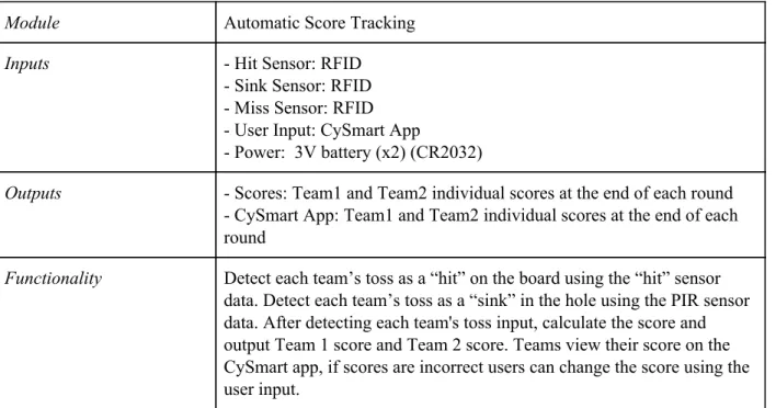
Automated Score Tracking Cornhole Game Level 0 Functional Decomposition
Module Automatic Score Tracking
Inputs - Hit Sensor: RFID
- Sink Sensor: RFID - Miss Sensor: RFID - User Input: CySmart App
- Power: 3V battery (x2) (CR2032)
Outputs - Scores: Team1 and Team2 individual scores at the end of each round - CySmart App: Team1 and Team2 individual scores at the end of each round
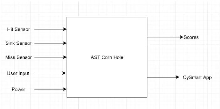
Figure 1. Block Diagram Level 0
TABLE IV
Automated Score Tracking Cornhole Game Level 1 Functional Decomposition RFID Module
Module RFID
Inputs - Hit Sensor: RFID
- Sink Sensor: RFID - Miss Sensor: RFID
Outputs - Bean bag position data: On board, in hole, off board
TABLE V
Automated Score Tracking Cornhole Game Level 1 Functional Decomposition CYBT-213043 Module
Module CYBT-213043 Mesh Evaluation Board
Inputs - Bean bag position data: RFID
- CySmart App: User Input - Power Supply: 3V
Outputs - Scores: Team1 and Team2 individual scores at the end of each round - CySmart App: Team1 and Team2 individual scores at the end of each round
Functionality The Mesh Evaluation Board is the module that ties everything together. The board is powered wirelessly using a 3V battery. It takes in position data to calculate the scores of each team. The board also takes in the user input from the CySmart App to correct any mistakes in the scores. Once all calculations have been done, the Mesh Evaluation Board communicates both teams' scores onto an external display and through the CySmart App for users to view their scores at the end of each round.
TABLE VI
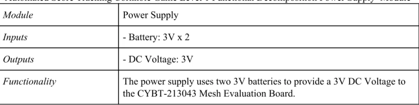
Automated Score Tracking Cornhole Game Level 1 Functional Decomposition Power Supply Module
Module Power Supply
Inputs - Battery: 3V x 2
Outputs - DC Voltage: 3V
Functionality The power supply uses two 3V batteries to provide a 3V DC Voltage to the CYBT-213043 Mesh Evaluation Board.
TABLE VII
Automated Score Tracking Cornhole Game Level 1 Functional Decomposition CySmart App Module
Module CySmart App
Inputs - User Input: User corrected score
- CYBT-213043: “hit”, “miss”, “sink” data for each team
Outputs - CySmart App: Updates the user corrected score in the app
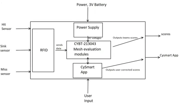
Figure 2: Block Diagram Level 1
Table VIII
Automated Score Tracking Gantt Table
TASK NAME START DATE END DATE START ON DAY* DURATION* (WORK DAYS) TEAM MEMBER
Project Plan
Abstract (Proposal) V1 9/19 9/23 0 4 Harrison
Requirements and Specifications (V1) 9/25 10/7 6 12 Mondy
Block Diagram 10/9 10/14 20 5 Daniel
Literature Search 9/25 10/21 6 26 Harrison
Gantt Chart 10/23 10/28 34 5 Mondy
Cost Estimates 10/23 10/28 34 5 Daniel
ABET Sr. Project Analysis 10/25 11/4 36 10 Harrison
Requirements and Specifications (V2) 11/6 11/11 48 5 Mondy
Research RFID, PIR, Vibration Sensing 11/11 11/22 53 11 Harrison
Report V1 9/23 11/15 4 53 Daniel
Design Review 11/21 12/6 63 15 Harrison
Order Components 12/2 12/16 74 14 Daniel
Report V2 11/29 12/9 71 10 Mondy
EE 461
Design Sink Sensor Implementation Method 1 1/6 1/20 109 14 Daniel
Design Miss Sensor Implementation Method 1 1/13 1/27 116 14 Harrison
Design User Input Implementation (button) 1/13 1/27 116 14 Mondy
Design User Input Implementation (Cysmart
App) 1/13 2/5 116 23 Daniel
Design Build Test Score Outputs 1/13 2/3 116 21
Design Review 1 1/6 2/3 109 28 Harrison
Design Hit Sensor Implementation Method 2 2/3 2/17 137 14 Mondy
Design Sink Sensor Implementation Method 2 2/3 2/17 137 14 Daniel
Design Miss Sensor Implementation Method 2 2/3 2/24 137 21 Harrison
Design User input Implementations (Buttons
and App) 2/10 2/24 144 14 Mondy
Design Review 2 2/10 2/24 144 14 Daniel
Decide on Method 1 or 2 for each input 2/25 3/2 159 6 Harrison
Build and Test Prototype 3/2 3/9 165 7 Daniel
EE 461 Demo 1/6 3/6 109 60 Mondy
EE 461 Report 2/28 3/13 162 14 Daniel
Prototype Model for Cypress Conference 1/6 3/22 109 76 Harrison
EE 462
Design Review 3 3/29 3/30 192 1 Daniel
Decide on Improvements to Project 3/30 4/6 193 7 Harrison
EE 462 Demo 4/1 5/31 195 60 Daniel
ABET Sr. Project Analysis 5/17 5/31 241 14 Mondy
Senior Project Expo Poster 5/17 5/31 241 14 Harrison
Figure 3: AST Gantt Chart
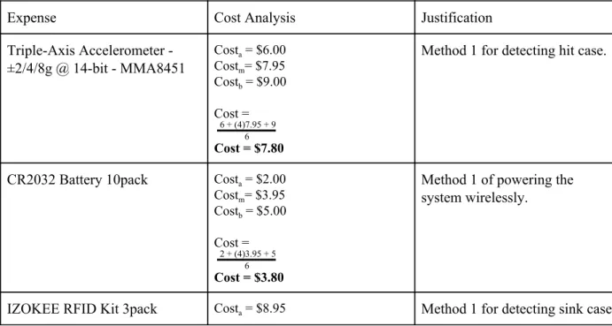
Table IX
Automated Score Tracking Cost Estimate Table
Expense Cost Analysis Justification
Triple-Axis Accelerometer - ±2/4/8g @ 14-bit - MMA8451
Costa = $6.00
Costm= $7.95
Costb = $9.00
Cost =
6 6 + (4)7.95 + 9
Cost = $7.80
Method 1 for detecting hit case.
CR2032 Battery 10pack Costa = $2.00
Costm= $3.95
Costb = $5.00
Cost =
6 2 + (4)3.95 + 5
Cost = $3.80
Method 1 of powering the system wirelessly.
Costm= $10.99
Costb = $12.95
Cost =
6 8.95 + (4)10.99 + 12.95
Cost = $10.97
RFID Sticker NFC tag Costa = $12.00
Costm= $14.98
Costb = $17.50
Cost =
6 12 + (4)14.98 + 17.50
Cost = $14.90
To be put inside corn hole bags for sink detection
Adhesive Velcro Tape Costa = $3.50
Costm= $5.36
Costb = $7.00
Cost =
6 3.5 + (4)5.36 + 7
Cost = $5.32
Method of securing system to cornhole boards safely and easily
Labor Costm=120 hrs
Costa=100 hrs Costb=150 hrs Cost=100+4(120)+1506
Cost=121.66 hrs per quarter Assuming same amount of work per quarter:
Total Hrs=3*121.66 Total Hrs=365 hrs
Typical hourly engineering intern wage: $30/hr
Cost of Labor = $30/hr * 365 Hr
Cost of Labor = $10950
EE 449 project says it is around 120 man hours of work. Let this represent out most realistic cost. If we are able to shave off 20 hrs of work that would be the most optimistic cost.
If an additional 30 hrs are required to finish that would be the most pessimistic cost.
Chapter 3. System Design
3.1 RFID
Radio Frequency Identification (RFID) is the method we chose to detect bean bag tosses for each team. Passive RFID is an accurate, inexpensive, and battery free way to detect interactions between objects. This method seemed the most plausible over other options such as image detection or pressure sensing, when considering cost, time, and accuracy.
3.1.1 RFID Reader
For the purposes of cornhole, the RFID reader needs to be able to detect multiple bags at the same time, instantly. In order to meet this requirement, we considered a couple different options. The two options considered are high-frequency (HF) RFID and ultra high-frequency (UHF) RFID. HF has an operating frequency of 13.56 MHz and UHF has an operating frequency between 860MHz - 960 MHz. Both HF and UHF have the ability to read tags simultaneously, UHF can read more at once, but both met this
requirement. We ultimately chose UHF as the best option due to the way we decided to assign the scores of a “hit”, “miss”, and “sink”. Part of the design is to use aluminum foil to block or attenuate signals from the tags to the reader in cases of a “hit” or “miss”. UHF is suited for this because its radio waves reflect off metal, allowing signals to be blocked with aluminum foil. HF prevents the radio waves from reflecting off metal, making it not ideal for the design. So the UHF RFID reader we chose for this project is the Sparkfun Simultaneous RFID Reader. This reader has a ThingMagic M6E UHF RFID Reader, and the board has an Arduino shield footprint so it can directly be connected to an Arduino-compatible board or microcontroller.
3.1.2 Passive RFID Tags
The RFID tags need to complement the reader. Since the reader we chose is UHF the tags also need to be UHF tags. The Sparkfun Simultaneous RFID Reader suggests to use UHF EPCglobal Gen2 tags, which is what we decided to use. Each tag has a Truly Unique ID (TID), so each one can be differentiated from one another by the reader. The TID is necessary in order to keep score for each team and identify how many points are awarded based on the position of the tag in relation to the cornhole board. The tags will be placed inside each bean bag.
3.1.3 Antenna
The RFID reader has a built in antenna on the board, however it only has a minimum amount of range. So to increase that range we need an external antenna. Like the tags, the antenna also needs to complement the reader, so we need a UHF RFID antenna. Antennas can either be linear or circular polarized. At the same gain as linear antennas, circular antennas have a shorter read range because they have to split the power between two planes rather than one. So to find an adequate circular polarized antenna with the proper gain is more expensive than a linear polarized antenna. We chose to use a linear vertical polarized UHF RFID antenna with a gain of 6dBi.
3.1.4 Aluminum signal blocking and attenuation
UHF RFID radio waves reflect off of metal. We used this knowledge to design a way to intentionally block and attenuate signals. The metal we decided to use is aluminum because it is inexpensive and easily accessible.
To fully block signals from bags that miss the board (“miss”), we need to line the sides of the cornhole board with sheets of solid aluminum foil. Since the RFID reader and antenna are located underneath the cornhole board, any signal off the board will be blocked. Aluminum can also be used to attenuate the signal strength. To attenuate the signals from bags that land on top of the board (“hit”), we need to line the back of the board with aluminum mesh. Aluminum mesh is a woven aluminum wire, so there are gaps in the mesh. These gaps allow some signal to get through the mesh, which results in attenuated signals. The attenuated signal strength is characterized into a range, so any bag that lands and has a signal strength within this range is considered a “hit” and will be assigned 1 point. Since the reader and antenna are located under the cornhole board, any bags that land in the hole (“sink”) will be close to the reader with no aluminum blocking or attenuating the signal. The non-attenuated signal strength is characterized into a range as well, so any bag that lands within this range is considered a “sink'' and is assigned 3 points. So the signal strength will be stronger for the bags that land in the hole, compared to the bags that land on the board.
3.2 BLE Mesh
Bluetooth Low Energy (BLE) Mesh is a network of wireless communication between many-to-many devices. BLE Mesh allows for many nodes to communicate messages to each other, this ability allows for the range of communication to broaden and increase the application for different types of uses. Cypress Semiconductor developed BLE Mesh devices and kits, which this project implements to demonstrate the uses for.
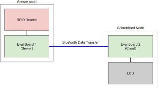
3.2.1 CYBT-213043-Eval Kit
The CYBT-213043-Eval Kit is an evaluation kit that allows for the user to develop bluetooth mesh networks and apply different applications. The CYBT-213043-02 module on the board is an integrated, programmable bluetooth module that enables BLE Mesh design. The eval kit is compatible with arduino shields, such as the Sparkfun Simultaneous UHF RFID Reader. The eval kit plugs into the RFID reader so the eval kit can act as a microcontroller to the RFID reader.
Figure 4: Data Flow from Sensor Server to Sensor Client Node
3.2.2 CYBT-213043-Mesh Kit
The CYBT-213043-Mesh Kit is also an evaluation kit, similar to the eval board. The mesh kit has the same CYBT-213043-02 bluetooth module as the eval kit, mentioned above. The difference between the two kits is the mesh kit includes many components such as sensors, RGB LEDs, and a user switch. These extra features implemented on the board allows the user to try multiple applications while integrating them in a bluetooth network.
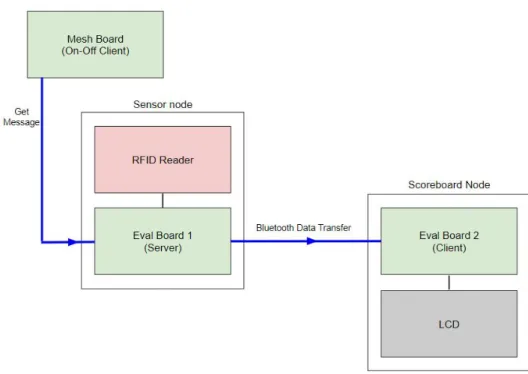
For the application of bluetooth communicated data, the project requires one CYBT-213043-Mesh kit. The mesh kit will utilize the user switch feature on the board to tell the server that it is the end of a round, and it is time to collect data. The mesh board will send the server a “get” message, basically telling the sensor node that it is time to collect data. In this case the mesh board will be acting as a simple on-off client node, where it sends a get message but ignores the response back. In our design, the server needs to be told when to retrieve the data from the RFID Reader and send it to the client; this could have been done multiple ways, but we decided to use the mesh board to tell the server to retrieve the data to
Figure 5: Data Flow from On-Off Client Node to Sensor Server
3.3 Score Board
The score board will display both teams' scores. The scores will update at the end of each round, upon the button press on the mesh board, from a user. The button press indicates the end of a round at which the data collection and bluetooth data transfer will occur, as mentioned above. The client eval board will receive the sensor data via bluetooth from the server eval board. This sensor data will then be displayed on a scoreboard.
3.3.1 LCD
There are many different types of displays, but two options were considered for this design: seven segment display and liquid crystal display (LCD). For ease of use and aesthetic purposes we believe that the LCD is a better fit for the design. An LCD allows us to easily display both teams' scores on a single display, and indicate which score belongs to each team.
As mentioned above, the LCD is connected to the client eval board and receives the current score data for each team, from that board. The LCD will update the current score upon the user button press on the mesh board, at the end of each round.
3.4 Design Revisions
The components mentioned in this section talk about how we revised the design of the system to better fit our timeline and capabilities after some trial and error runs with the original design.
3.4.1 Arduino
We originally started using an arduino to test the functionality of the RFID reader because we are comfortable with arduino. Once we had that code working on the arduino, we tried to transfer it into the Cypress IDE, Modustoolbox, in order to program the CYBT-213043 boards. There needed to be a few tweaks to the code due to the difference in Arduino IDE and Modustoolboc IDE. However, we came across some issues. We tried a few different things, but it came to the point that our group decided to split the processing between an arduino and the CYBT-213043 boards in order to meet the scope of our
timeline for the project. This decision was made because our group was new to the topics of bluetooth and mesh, we believe that our focus should be on the transfer of data through bluetooth rather than the
processing of the RFID data.
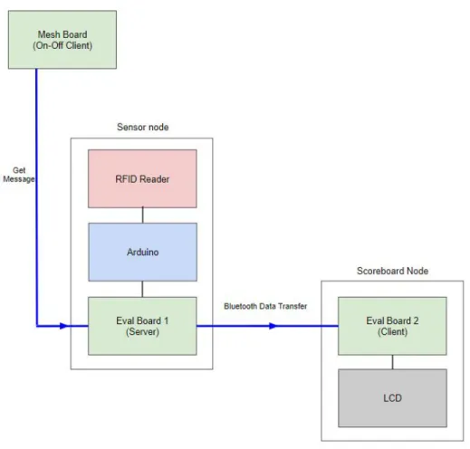
Now, the RFID reader is plugged into the Arduino Uno, which processes the sensor data from the reader. The arduino is hardwired to the server eval board; so now the server eval board receives the sensor data from the arduino. The server eval board will take in the sensor data and send it via bluetooth to the client eval board. With this design, the focus for the CYBT-213043 Eval boards is just on sending and receiving the sensor data. To understand the new flow, please see Figure 6, below.
Figure 6: Dataflow from On-Off Client to Sensor Server with Arduino
3.4.2 CySmart
Chapter 4. Development and Construction
4.1 Hardware
To meet the design requirement for all hardware to fit inside a standard 2x4 foot cornhole set, all hardware was assembled within the cornhole board.
4.1.1 Sensor Node
The RFID reader is connected to the arduino. The external antenna is connected to the RFID reader. To connect the external antenna, on the reader you need to clear the solder from the trace antenna and solder closed the jumper to the u.FL connector. This allows for the M6E Nano module on the reader to connect to the external antenna rather than the onboard antenna. See Figure 7, below.
Figure 7: RFID Reader Antenna Select Solder Jump
4.1.2 Cornhole Board Aluminum
In order to block signals from bean bags tossed outside of the board, the four sides of the board are lined with aluminum foil down to the ground as shown in Figure 8.
To attenuate the signal strength of bean bags landing on the surface of the cornhole board, we tried a few methods. The first method we tested was aluminum mesh. Lining the back of the board with this resulted in full blockage of the signal. The issue with the aluminum mesh seems to be the size of the gaps between the woven wire. The gaps are too small, not allowing any radio wave to make it through. Perhaps if we tried an aluminum mesh with larger gaps, the result would have been better.
The second method we tested was uniform holes in aluminum foil. This method resulted in signal attenuation, however the attenuation was not consistent enough to characterize a range. The issue with this method is the difficulty of cutting uniform circles in aluminum foil. The foil is flimsy and is hard to work with when it comes to cutting out circles.
The third method we tested was strips of aluminum foil, arranged in a diamond pattern. This method is similar to the uniform circle method, however, it is much easier to handle cutting strips of aluminum foil and arranging them in a diamond pattern. When tested, this method gave the most consistent results. Figure 9 shows the aluminum foil pattern used to attenuate the signal strength.
Figure 9: On Board Attenuation Pattern
4.2 Firmware Development
Two sensor models were used for development of firmware for the CYBT-213043 Eval boards. Cypress Semiconductor includes code snips of these models, and more, in Modustoolbox. These models define the functionality set up and include many functions that can be used to develop firmware for these boards. The sensor models are a method that bluetooth mesh uses to interface between sensors.
4.2.1 Sensor Server Model
Due to forced isolation, the group decided to keep the user button on the server eval board, rather than on the on-off client mesh board. This decision allowed us to move forward with the rest of the project.
The function, hal_gpio_app_test_input, initializes pins 1-5 on the eval board as the RFID data score input pins. The way the arduino is packaging the data is four bits for the score and one bit to signify the team. So pins 1-5 receive the data from the arduino. Pin 1 is the least significant bit of the RFID score data, Pin 4 is the most significant bit of the RFID score data, and Pin 5 is the team bit. The last two lines of the function configure the user defined switch on the eval board, and then initializes that switch as an interrupt.
void hal_gpio_app_test_input(void) {
uint8_t index = 0;
//initializes pins 1-5 as RFID data score input pins
wiced_hal_gpio_configure_pin(WICED_P01, GPIO_INPUT_ENABLE, GPIO_PIN_OUTPUT_LOW);//LSB RFID data bit
wiced_hal_gpio_configure_pin(WICED_P02, GPIO_INPUT_ENABLE, GPIO_PIN_OUTPUT_LOW); wiced_hal_gpio_configure_pin(WICED_P03, GPIO_INPUT_ENABLE, GPIO_PIN_OUTPUT_LOW);
wiced_hal_gpio_configure_pin(WICED_P04, GPIO_INPUT_ENABLE, GPIO_PIN_OUTPUT_LOW);//MSB RFID data bit
wiced_hal_gpio_configure_pin(WICED_P05, GPIO_INPUT_ENABLE, GPIO_PIN_OUTPUT_LOW);//will serve as Team bit
//automatically maps to correct pins for any kit
wiced_hal_gpio_configure_pin(WICED_GPIO_PIN_BUTTON,(GPIO_INPUT_ENABLE|GPIO_PULL_DOWN|GPIO_EN_INT_RISING_EDGE),GP
IO_PIN_OUTPUT_LOW);
//initialized SW3 user defined switch as interrupt
wiced_hal_gpio_register_pin_for_interrupt(WICED_GPIO_PIN_BUTTON, hal_gpio_app_interrrupt_handler, NULL); }
Code Snip 1: Sensor Server hal_gpio_app_test_input Function
void set_RFID_data(int8_t v, int8_t w, int8_t x, int8_t y, int8_t z) //Based on data received from Arduino, this function sets RFID data
{
if(v == 1) {
RFID_data+=1; }
else
{
RFID_data+=0; }
if(w == 1) {
RFID_data+=2; }
else
{
RFID_data+=0; }
if(x == 1) {
RFID_data+=4; }
else
{
RFID_data+=0; }
if(y == 1) {
RFID_data+=8; }
else
{
RFID_data+=0; }
if(z == 1) {
RFID_data+=16; }
else
{
RFID_data+=0; }
}
Code Snip 2: Sensor Server set_RFID_data Function
The function seen below is the interrupt handler for the button press. Once the button is pressed,
An initial issue occured when we were setting mesh_sensor_RFID_current_score = RFID_data in the sensor report handler. However, we realized that the report handler function would never be called unless the sensor client requested a “get” operation, which we had not set up in the client. So by doing this, the mesh_sensor_RFID_current_score was never being set since the code didn’t go into the sensor report handler in the server model. So we learned that mesh_sensor_RFID_current_score needs to be set in the interrupt handler, since we are using a button interrupt. The report handler could be ignored for our case, since we are not using the client to send a “get” message.
void hal_gpio_app_interrrupt_handler(void *data, uint8_t pin) //Jump to this function once the button is pushed
{
a = wiced_hal_gpio_get_pin_input_status(WICED_P01); //These variables store the current state on the GPIO pins
b = wiced_hal_gpio_get_pin_input_status(WICED_P02); c = wiced_hal_gpio_get_pin_input_status(WICED_P03); d = wiced_hal_gpio_get_pin_input_status(WICED_P04); e = wiced_hal_gpio_get_pin_input_status(WICED_P05); set_RFID_data(a, b, c, d, e);
mesh_sensor_RFID_current_score = RFID_data;
wiced_bt_mesh_model_sensor_server_data(MESH_SENSOR_SERVER_ELEMENT_INDEX,
WICED_BT_MESH_PROPERTY_RFID_VALUE, NULL); //This function sends a status message to the mesh which contains RFID data
}
Code Snip 3: Sensor Server hal_gpio_app_interrupt_handler Function
Since we are using the function hal_gpio_app_test_input to configure the button, the function table needs to be revised so hal_gpio_app_test_input is included. This is important because the function table tells the provisioner what functions to use. Without including this function, the provisioner will try to set up the button on its own.
wiced_bt_mesh_app_func_table_t wiced_bt_mesh_app_func_table = {
mesh_app_init, // application initialization
hal_gpio_app_test_input, // Button processing
NULL, // GATT connection status
NULL, // attention processing
mesh_app_notify_period_set, // notify period set
NULL, // WICED HCI command
NULL, // LPN sleep
NULL // factory reset
};
Code Snip 4: Sensor Server Function Table
To view the full sensor server code, please see Appendix B.
4.2.2 Sensor Client Model
The sensor client waits for a status message sent from the server. Once the status message is received the client reads the sensor data that the server sent via bluetooth.
WICED_BT_MESH_SENSOR_STATUS. When the server sends out this status message, the client will go into the mesh_sensor_client_message_handler; here it will find the case for the particular status message and execute the code under the case. Once the status message is received the function
wiced_bt_mesh_sensor_status_data_t is called. This function allows for the sensor status data structure to be exchanged between the application and the sensor model. One of the properties of the function is the raw_value of the sensor status data. The raw_value is stored in data using thememcpy function. The value stored in data is then displayed on the client terminal in Modustoolbox, using WICED_BT_TRACE.
void mesh_sensor_client_message_handler(uint8_t element_idx, uint16_t addr, uint16_t event, void *p_data) {
WICED_BT_TRACE("*****data*****:\n"); //Displays trace statement on Terminal
uint8_t data[100]={0}; //Used to store the received RFID data
//Data that is received is added on to the previous value stored in this array
#if defined HCI_CONTROL
wiced_bt_mesh_hci_event_t *p_hci_event;
#endif
WICED_BT_TRACE("sensor clt msg:%d\n", event);
switch (event)
{
case WICED_BT_MESH_TX_COMPLETE:
WICED_BT_TRACE("tx complete\n"); break;
#if defined HCI_CONTROL
case WICED_BT_MESH_SENSOR_DESCRIPTOR_STATUS:
if ((p_hci_event = wiced_bt_mesh_alloc_hci_event(element_idx)) != NULL) {
p_hci_event->src = addr;
mesh_sensor_desc_hci_event_send(p_hci_event, (wiced_bt_mesh_sensor_descriptor_status_data_t *)p_data);
} break;
case WICED_BT_MESH_SENSOR_STATUS://This is the only case we are using because the sensor node will send a
STATUS message with RFID data
memcpy(data, ((wiced_bt_mesh_sensor_status_data_t *)p_data)->raw_value,
((wiced_bt_mesh_sensor_status_data_t *)p_data)->prop_value_len); //Used to add newly received RFID data to previous value
WICED_BT_TRACE("data:%B\n", data); //Displays data in terminal
break;
The function table for the sensor client model only requires mesh_app_init, all other functionality is NULL since nothing else is required to be configured.
wiced_bt_mesh_app_func_table_t wiced_bt_mesh_app_func_table = {
mesh_app_init, // application initialization
NULL, // Default SDK platform button processing
NULL, // GATT connection status
NULL, // attention processing
NULL, // notify period set
NULL, // WICED HCI command
NULL, // LPN sleep
NULL // factory reset
};
Code Snip 6: Sensor Client Function Table
To view the full sensor client code, please see Appendix C.
4.2.3 Provisioning
Once both the sensor server model and the sensor client model are programmed onto the eval boards, the two models need to be grouped into the same network in order to talk to each other.
There are a few ways to provision the models. The first way is through the built-in provisioner in Modustoolbox, ClientControlMesh. ClientControlMesh is an application that uses a separate evaluation board in order to run the Bluetooth Stack and talk to the other boards. The second way to provision is to use another application provided by Cypress, however this one is not built-in to Modustoolbox and will have to be searched for in file explorer under the workspace, reference Appendix F for file path. This second application is called MeshClient. MeshClient is similar to ClientControlMesh, but the main difference is MeshClient does not require an external board to provision; it uses the bluetooth radio on the computer to run the Bluetooth Stack. The third way to provision is to use the phone application,
MeshApp.
We tried all three ways and came across some issues. The first application we used was
4.2.4 Arduino Firmware
The Arduino in this system is responsible for allowing the RFID reader to communicate with the server sensor. Once triggered The arduino will trigger a two second long continuous read that will allow for the reader to detect all present tags near the sensor.
//Read sequence
if (button_bool == 1){ //Read tags for 2 seconds
while (millis() - start_time <= 2000){
read_tags(); }
//Trigger print and output sequence
print_info = 1; if (print_info == 1){ print_data();
//reset appropriate variables
print_info = 0; button_bool = 0;
int EPClist[10] = {0,0,0,0,0,0,0,0,0,0}; int rssilist[10] = {0,0,0,0,0,0,0,0,0,0}; }
}
Code Snip 7: RFID Read Sequence
During the read sequence the arduino will maintain two lists. The first being boolean based list called
EPClist that will indicate which of the RFID tags have been read during the continuous read, the next being a list that will correspond to the information in EPClist and provide the rssi (receiver signal strength indicator) which we use to determine if a bag is on the board or in the hole as shown in Code Snip 8.
// Assign point to proper team base on bag position
if ((bag_num) % 2 == 0){ //Even numbered bags correspond to team 1
// Missed bags will not have an rssi value
if (bag_rssi == 0){ t1_score = t1_score; }
// Signal of bags on the surface will be attenuated below -39 dbm
t1_score = t1_score + 1; else if (bag_rssi < -39){ }
// Bags with rssi signal between 0 and -39 dmb will be classified as through the hole
else{
t1_score = t1_score + 3; }
}
else{ //Odd numbered bags correspond to team 2
// Missed bags will not have an rssi value
if (bag_rssi == 0){ t2_score = t2_score; }
// Signal of bags on the surface will be attenuated below -39 dbm
else if (bag_rssi < -39){ t2_score = t2_score + 1; }
// Bags with rssi signal between 0 and -39 dmb will be classified as through the hole
else{
t2_score = t2_score + 3; }
}
Next, the Arduino will determine which team will receive points after the round and trigger the team bit to adjust accordingly. The team bit will be set to 1 for team 1 and 0 for team 2. This is shown in Code Snip 9 below.
//If team 1 scored higher than team 2 set team bit to 1
if (t1_score > t2_score){ digitalWrite(team_out, HIGH); score_diff = t1_score - t2_score; Serial.print("team 1: "); }
//If team 2 scored higher than team 1 set team bit to 0
else if (t2_score > t1_score){ digitalWrite(team_out, LOW); score_diff = t2_score - t1_score; Serial.print("team 2: "); }
//If each team score equal exit function
else{
return
}
Code Snip 9: Team Assignment
Finally, the Arduino will set the output score pins high or low depending on the difference in score. The score pins represent a 4 bit binary number allowing to display the maximum score difference of 12.
//Send a score difference of 2
else if (score_diff == 2){ Serial.println("2"); digitalWrite(score_0, LOW); digitalWrite(score_1, HIGH); digitalWrite(score_2, LOW); digitalWrite(score_3, LOW); }
Code Snip 10: Example Score Output
Chapter 5: System Performance
This chapter overviews the final performance of the entire system. The final results are compared to the engineering requirements from the project plan section. Also the final expenses are reviewed.
5.1 System Requirement Check
This section takes the original engineering specifications and compares how well the final results accomplished meeting the specification.
*Due to forced isolation, certain specifications needed to be adjusted.
Table X: Engineering Specifications vs. Final Design Results
Engineering Specifications Final Results
2 feet x 4 feet the exception of an external eval board used for The system fits within the cornhole board, with the user button to indicate the end of a round.
CYBT-213043 Mesh Evaluation Boards CYBT-213043 Eval Boards were used rather than the Mesh boards due to the availability of pins. The Eval and Mesh boards contain the same
bluetooth module.
Boards will operate without external power
*
Automatic Score Tracking The system is able to track score and send the data via bluetooth to display on the client terminal in Modustoolbox and updates upon button press.
Enclosed housing for electronics (IP51) *
User intervention possible
*
Mobile Phone application
*
5.2 Expense Check
Table XI: Automated Score Tracking Senior Project Actual Cost
Automated Score Tracking Senior Project Actual Cost
Part Count
Actual Cost ($) each
Shipping
($) Tax ($) Total ($) Donated
CYBT-213043 Eval Board 2 0.00 0.00 0.00 0.00 Yes
CYBT-213043 Mesh Kit 2 0.00 0.00 0.00 0.00 Yes
Custom Cornhole Game Set 1 0.00 0.00 0.00 0.00 Yes
Arduino Uno 1 0.00 0.00 0.00 0.00 No
SparkFun Simultaneous RFID
Reader - M6E Nano 1 224.95 8.99 17.43 251.37 No
UHF RFID Antenna 1 37.95 9.36 3.66 50.97 No
UHF RFID Tag - Adhesive (Set of
5) 2 1.95 11.76 0.15 15.81 No
Aluminum Foil Roll 1 0.00 0.00 0.00 0.00 No
Overall Total 318.15
5.3 Overall Performance
Below in Figure 10 we see one example of the information generated by the Arduino. Currently there are four bags recognizable to the system. Bag zero is detected with an RSSI of -38 dbm this indicates that it is through the hole, giving team 1 three points. Next we see bag one has an RSSI of -62 dbm indicating that it has landed on top of the game board, giving team 2 one point. Bag 2 does not have an RSSI value meaning that it landed off of the game board, not contributing any points to the assigned team. Following this, bag 3 is detected on the board, adding one point to team 2’s score, while bag 4 has missed the board. Once all the bag data is received, the Arduino will calculate the total round score for each team and then calculate who this round will affect the game score. The last line in Figure 10 shows that the round will end with team one receiving one point to their overall score.
Figure 11 and 12 show the data that has been received by the sensor client board. Figure 11 is the data before the Arduino sends it the new round data and Figure 12 is after receiving the new data. We can see that the data value goes from a hex value of 71 to 82. Using a programming calculator shown in Figure 13, we can see that the difference of these two data values gives you a binary result of 0001 0001. This aligns with the communication protocol that was assigned between the arduino and the mesh node (000[team indicator] [score difference]). The 1 indicates that team 1 will be gaining points and the 0001 indicates that they will be receiving 1 point. Figures 14, 15, and 16 shows this process again after another round of play ending with team 2 receiving one additional point. 1
Figure 11: Previous Sensor Server Data
Figure 12: New Round Sensor Server Data
Figure 13: Round Difference Calculation
Figure 14: New Round Arduino Serial Output
Figure 15: New Round Seneser Server Data
Figure 16: New Round Score Calculation
Chapter 6: Conclusion
6.1 Accomplishments
The Automated Score Tracking system for cornhole has a larger scope than was originally thought. However, the group was able to accomplish a working system in the end. The system is able to
distinguish between the three outcomes of a bean bag toss, process that data with an arduino, and send it via bluetooth using the Cypress eval boards. There was definitely a lot to learn from this project,
6.2 Issues
We want to highlight a few issues that we came across during the development of this project to inform future students about and how to handle them.
6.2.1 Phone MeshApp
MeshApp is a provisioning app for iPhone and Android. One detail we did not know was that MeshApp is used for provisioning lighting related models. We found that we were able to provision an example model that was related to lighting in MeshApp. However, when it came to our sensor models the status message from the sensor server was never making it to the sensor client because it seems MeshApp only allows lighting related messages to transmit. We suggest using MeshClient as the provisioning tool. As a reminder MeshClient can only be used on a Windows operating system.
6.2.2 Mac OS
One of our group members uses a Macbook, many things worked the same as it did on Windows. However, we noticed that the accessibility to certain things like MeshClient were not available for Mac OS. So we suggest having access to a Windows operating system to make sure everything runs smoothly.
6.2.3 Baud rate for terminal plug-in
Once we started testing our system we wanted to view and debug certain parts of the code. We downloaded a terminal plug-in, TM Term . However, the terminal was not printed in english. This 2
definitely was a baud rate issue. In the settings for the built-in terminal, there was a drop down menu to select from ten different baud rates. The baud rate for the boards is 115200, so this is what we set it to. This didn’t help, so we tried every baud rate on the list but none of them worked. We talked to Cypress engineer, Greg, and he mentioned that the baud rate needs to be 921600; this is not one of the options on the drop down menu. So there is a way to change the baud rate from 921600 to 115200, so you can select the correct baud rate on the drop down menu. Please see Appendix E for instructions.
6.3 Future Improvement Opportunities
There is always room for improvement, and considering the scope of the project there can be a few large improvements made to make the project run smoother and accomplish the original goal to showcase Cypress’ Bluetooth Mesh technology.
6.3.1 More Mesh Nodes
The goal is to showcase a mesh network, so the more nodes that are in the network, the more “meshy” it is. We included two nodes communicating to each other in a network. To improve, a button node can be added using a separate mesh board. This was in our original design plans, but time did not permit for us to include this third node in the network. Other nodes such as a motion sensor can use the PIR sensor on the mesh kit. It can be placed on the hole of the cornhole board and communicate with the sensor node to determine which team made a “sink” and will then flash an LED strip the color of the team that just scored. There are so many different possibilities with Bluetooth Mesh and the CYBT-213043 Mesh Kits can help bring the possibilities to reality.
6.3.2 Move data processing from arduino to CYBT-213043 Boards
References
[1] Cypress Semiconductor, “Ultra Low Power, BLE/BR/EDR Bluetooth 5.0 SoC,” CYW20819 datasheet, March 2018 [Revised May 2019].
[2] M. Schrag, The Sports Rules Book. 4th ed., Champaign, IL: Human Kinetics, 2018, pp. 86-89.
[3] J. Tang, and C. Chen. "A Billiards Track and Score Recording System by RFID Trigger," Procedia Environmental Sciences, vol. 11, no. PA,pp. 465–470, 2011.
[4] American Cornhole Organization. “Official Rules for the Sport of Cornhole” Internet: https://americancornhole.com/rules/, 2016 [Oct. 2019].
[5] M. Baert, J. Rossey, A. Shahid, and J. Hoebeke, “The Bluetooth Mesh Standard: An Overview and Experimental Evaluation,” Sensors, vol. 18, no. 8, p. 2409, Jul. 2018.
[6] D. Solda, et al. Getting Started with Bluetooth Mesh. Cypress Semiconductor Appl. Note AN227069.
[7] S. Bodapati, et al. “Systems and Methods to Detect Cross Reads in RFID Tags,” United States Patent 8854190, Oct. 7, 2014.
[8] A. Polo, et al. “Bluetooth low energy automation mesh network,” United States Patent 10440546, Oct. 8, 2019.
[9] A. Nikoukar, et al. “Low-Power Wireless for the Internet of Things: Standards and Applications,” IEEE Access, vol. 6, Nov. 2018, [DOI: 10.1109/ACCESS.2018.2879189]. Available:
https://ieeexplore-ieee-org.ezproxy.lib.calpoly.edu/document/8528458/citations#citations. [Accessed Oct. 2019].
[10] S. M. Darroudi, R. Caldera-Sànchez and C. Gomez, "Bluetooth Mesh Energy Consumption: A Model," Sensors (Basel, Switzerland), vol. 19, (5), 2019. Available:
http://ezproxy.lib.calpoly.edu/login?url=https://search-proquest-com.ezproxy.lib.calpoly.edu/docview/219 3162340?accountid=10362. DOI: http://dx.doi.org.ezproxy.lib.calpoly.edu/10.3390/s19051238.
[11] M. Woolley, “Bluetooth Mesh Models: Technical Overview,” Version 1.0, March 2019.
[12] R. Heydon, J. Tanner, V. Zhodzishsky, et. al. “Mesh Model: Bluetooth Specification,” Revision v1.0, Jul. 13, 2017.
[14] Simultaneous RFID Tag Reader Hookup Guide. Sparkfun, 2020 [Online]. Available:
https://media.digikey.com/pdf/Data%20Sheets/Sparkfun%20PDFs/Simultaneous_RFID_Tag_Reader_Ho okupGuide_Web.pdf.
Appendix A. Senior Project Analysis
Project Title: Automated Score Tracking for the Game of Cornhole
Student’s Name: Harrison Overturf, Daniel Hurwitz, Mondona Behroozian
Advisor’s Name: Dale Dolan
Date: 11/18/19
1. Summary of Functional Requirements
Describe the overall capabilities or functions of your project or design. Describe what your project does. (Do not describe how you designed it).
The Automated Score Tracking (AST) Cornhole Game introduces wireless communication and modularity to the game of cornhole. AST eliminates the responsibility for teams to manually keep track of their score from round to round. Users easily connect to other AST game boards by pairing the devices via bluetooth. The game begins once the boards pair. Players toss their bean bags, with points being awarded as per usual with one point being given to bags landing on the board and three points being given to bags that land through the hole. AST detects all possible outcomes for a bean bag toss including a “sink” where a bag lands in the hole located on the board, a “hit” where a bag lands and stays on the board, or a “miss” where the bag misses the board completely. This system reduces scoring errors made by participants by continually tracking the progress of the game, allowing users to make changes to the scores as necessary. This system makes the game of cornhole simpler and more enjoyable.
2. Primary Constraints
Describe significant challenges or difficulties associated with your project or implementation. For example, what were limiting factors, or other issues that impacted your approach?
3. Economic
• What economic impacts result? Consider:
Human Capital – What people do.
Automating the score for cornhole allows people to have more social interaction during the game. Not having to worry about keeping track of a score makes people's lives easier, which makes the game more enjoyable.
Financial Capital – Monetary instruments.
Based on the cost estimates provided above the only financial capital needed for the completion of the AST project is the $200 stipend provided for each team member by the Cal Poly Electrical Engineering Department.
Manufactured or Real Capital – Made by people and their tools.
The AST project requires the CYBT-213043-Mesh evaluation module manufactured by Cypress Semiconductor to implement mesh functionality and allow the user to get real time score data on their mobile device. Each AST enabled system will consist of four mesh evaluation modules.
Natural Capital – The Earth’s resources and bio-capacity.
The AST system requires two standard cornhole boards which are typically made from pine wood. The dimensions of the boards are listed below to show the amount of wood required to make the boards.
● (2) 24" x 48" pieces of 1/2" plywood for the surface
● (4) 2x4 x 48" for the frame
● (4) 2x4 x 21" for the frame
• When and where do costs and benefits accrue throughout the project’s lifecycle?
The majority of costs will accrue during the research and development phase of the project in which external components will need to be purchased in order to successfully implement the AST system. The benefits will begin occurring once the system is completed and users are able to play the automated cornhole game.
• What inputs does the project require? How much does the project cost? Who pays?
The project inputs are as follows:
● CYBT-213043-Mesh evaluation kit (x4) provided by Cypress Semiconductor
● Cornhole Board(s) (x2) provided by Cypress Semiconductor
● Passive RFID tags for bean bags paid for using student stipend provided by Cal Poly EE department
● Project Enclosure paid for using student stipend provided by Cal Poly EE department
● Extra External Parts also to be paid for using funds provided by Cal Poly EE department
Original estimated cost of component parts (as of the start of your project).
Cypress Semiconductor donated the cornhole game boards as well as the EZ-BT Mesh Evaluation boards. The additional components estimated cost is $42.79.
Actual final cost of component parts (at the end of your project)
Attach a final bill of materials for all components.
Additional equipment costs (any equipment needed for development?)
The only external equipment that we will need throughout the development of the AST corn hole game is a set of test board to use while testing different implementations of sensors to find the best methods.
• How much does the project earn? Who profits?
Estimates show the project will earn around $1,105,650 per year. These profits will go to Cypress Semiconductor while the users of the system will profit in entertainment. Cypress will also benefit from the marketing that this project will bring to their BLE Mesh enabled products. The company will profit monetary wise, while the users profit in entertainment.
• Timing
When do products emerge? How long do products exist? What maintenance or operation costs exist?
The American Cornhole League was founded in 2015, since then the popularity of the game of
cornhole has increased. Now, the game has national tournaments and entertains outdoor gatherings. The beginning of summer is a popular time for people to purchase outdoor games which is a good time for the products release.The product will retain its quality and functionality if treated with care. The external battery life is the only maintenance needed after purchase.
Original estimated development time (as of the start of your project), as Gantt or Pert chart
The estimated total development time for the project is 360 man-hours.
Actual development time (at the end of your project), as Gantt or Pert chart
4. If manufactured on a commercial basis:
• Estimated number of devices sold per year
To get an estimate for the number of devices that would be sold a year we first have to look at how many sets of the base game are sold a year, estimates for this are within 150k-200k games per year. We then need to consider that we would be taking a small portion of this market, estimated at around 15%, which would give us an estimated number of devices sold per year of 22.5k-30k.
• Estimated manufacturing cost for each device
For the development of the board, we will need to use two of the Cypress CYBT-213014-MESH EZ-BT Module Mesh Evaluation boards. We are able to purchase four of these boards for $119.99 ($29.99 per board). Then for the rest of the electronics, we would estimate about an extra $20 for the sets. Finally an extra $18 for the wood needed to construct the boards themselves. In addition to the game boards we will also need to produce compatible tossing baggies so that they can interact properly with the board sensors, we estimate that the baggies will cost around $1.30-$2 a piece ($10.40-$16 for a complete set) to produce depending on what sensors need to be added. In the future, we would expect this price to go down as we negotiate prices of components in bulk. So before labor, the cost of manufacturing for each set of boards would be $113.98.
• Estimated purchase price for each device
After doing some competitive analysis we can see that a standard pre-assembled cornhole set is up for purchase at around $100-$120 and then sets with artwork range for about $200-$300. After researching a large toy company’s profit margins, we see that the profit margins they have aimed for in recent years is 43%. we have to take into consideration the cost of labor, packaging, and distribution as well. So if we assume a standard distribution cost of $5 per item, a standard packaging cost of $5, and $30 an hour for a total of 5 hours to manufacture, as well as including the total cost to manufacture the set of boards. When we do the profit margin analysis, the total purchase price for the AST integrated cornhole game is $391.79. Please see math below:
($113.98+$5+$5+($30x5hr))(1.43) = $319.79
• Estimated profit per year
The Revenue per year for AST integrated cornhole games would be = $ per year 6, 50 units sold per year 19.79 dollars per unit
2 2 × 3
The profit per year for AST integrated cornhole games would be
8,394,487.5 - (26,250× (113.98+ 5 + 5 + (30x5)))= $1,202512.5 per year
• Estimated cost for user to operate device, per unit time (specify time interval)
when there is a continuous current of 3.1mA. On average, a game of cornhole lasts about an hour, so the users will need to change the battery about every 53 cycles.
5. Environmental
• Describe any environmental impacts associated with manufacturing or use, explain where they occur and quantify.
The batteries used for powering the system contain Lithium. The process to obtain Lithium impacts local towns by destroying land and depleting water. One way to limit this impact is to use rechargeable batteries. Another environmental impact is the use of wood to manufacture the cornhole game boards, which contributes to deforestation. The electrical components used for the system contribute to
E-waste, one way to avoid this harmful impact is to use RoHS compliant components. RoHS compliant components restriction of the Use of certain Hazardous Substances in Electrical and Electronic
Equipment.
• Which natural resources and ecosystem services does the project use directly and indirectly?
The natural resources the project uses are lithium and wood.
• Which natural resources and ecosystem services does the project improve or harm?
The project harms the forests through the use of wood to manufacture the game boards. The lithium mining affects humans that live in the local area due to the removal of water from land.
• How does the project impact other species?
6. Manufacturability
Describe any issues or challenges associated with manufacturing.
Manufacturing the devices is fairly straight forward. Once the BLE-mesh boards are flashed with the game code all that is needed to be done is for each device to be properly wired and attached to the physical cornhole boards. The baggies will also need to be sewn together with the needed sensors.
7. Sustainability
• Describe any issues or challenges associated with maintaining the completed device, or system.
The most important aspect of device maintenance will be changing the battery. Because the devices will have both dust and water resistance they should be fine in most conditions. But the user will be advised to store the boards indoors when they are not in use.
The cornhole boards used in this project are made from wood while the rest of the materials associated with the external circuitry consist of various plastics, silicon, rubber, and metal. The wood used for the cornhole boards represent the largest environmental impact due to the fact that trees must be cut down to harvest the wood.
• Describe any upgrades that would improve the design of the project.
One potential upgrade to the system design would be to use only recycled wood for the conrhole boards. This would reduce the impact on the environment because instead of cutting down more trees for the conrhole boards, we could use recycled materials.
• Describe any issues or challenges associated with upgrading the design.
Using recycled wood would require the team to find a cheap and reliable source of recycled wood. This would also require us to build our own cornhole boards out of recycled materials which would add more time to the overall project as well as more cost for tools to build the boards.
8. Ethical
Describe ethical implications relating to the design, manufacture, use, or misuse of the project. Analyze using one or more ethical frameworks in addition to the IEEE Code of Ethics.
Characterization of system accuracy is a big concern in regards to the development of this project. Ideally the system would be able to report accurate scores 100% of the time but this may not be achievable. Much testing will be done in order to honestly and realistically state the scoring accuracy of the system to be in line with the third tenet of the IEEE Code of Ethics, “to be honest and realistic in stating claims or estimates based on available data.
9. Health and Safety
Describe any health and safety concerns associated with design, manufacture or use of the project.
Cornhole is typically played outside during fair weather days. Due to this, users should be aware of the health hazards associated with playing outside including things like exposure to the sun, air purity levels, as well as physical harm that can arise due to physical activity. Users who cannot play a normal game of cornhole without risking physical harm are not recommended to play with the AST version of cornhole.
10. Social and Political
• Describe social and political issues associated with design, manufacture, and use.
not everyone can afford it. The affordability of the product strikes a social issue to those in a lower economic class.
• Who does the project impact? Who are the direct and indirect stakeholders?
This project will impact those who use the system which will most likely be future Cal Poly electrical engineering students who will play with the cornhole boards. The boards used in this project have the Cypress Semiconductor logo on them which will lead to Cypress receiving more publicity amongst Cal Poly electrical engineering students who use the cornhole boards.
• How does the project benefit or harm various stakeholders?
The project will benefit the users of the system because they will be able to reduce stress and relax as they play cornhole without having to worry about the score. Cypress Semiconductor will benefit from the free marketing that the boards will generate for the company. The project may inspire other electrical engineering students to apply to jobs at Cypress due to the project.
• To what extent do stakeholders benefit equally? Pay equally? Does the project create any inequities?
All stakeholders benefit equally. Those who use the system to play cornhole will benefit from the physical activity and stress reduction due to playing the game. Cypress Semiconductor will benefit from the free publicity that the boards will generate for them.
• Consider various stakeholders’ locations, communities, access to resources, economic power, knowledge, skills, and political power.
11. Development
Describe any new tools or techniques, used for either development or analysis that you learned independently during the course of your project.