User's Manual
Safety Information . . . 7
About the Book . . . 9
Chapter 1
Security . . . 11
Security . . . 11
Internal Security . . . 12
External Security . . . 13
Secure Access to Direct Addresses . . . 15
Chapter 2
TSX ETG 1000 Module: General . . . 17
Presentation . . . 17
2.1 Description of the TSX ETG Module . . . 18
Presentation . . . 18
About ETHERNET. . . 19
Presentation . . . 20
General Information about the TSX ETG Module . . . 21
Summary of the Module Functions . . . 22
Chapter 3
Services . . . 23
Presentation . . . 23
3.1 Modbus Communication Function. . . 24
Presentation . . . 24
Modbus Communication. . . 25
Modbus Server . . . 26
3.2 TCP/IP Messaging . . . 30
Presentation . . . 30
BOOTP/DHCP(FDR) Services - General. . . 43
TSX ETG 1000 as BOOTP Client . . . 44
TSX ETG 1000 as DHCP(FDR) Client. . . 45
3.4 SNMP Server . . . 47
SNMP Communication in UDP/IP . . . 47
3.5 SMTP Server . . . 50
Email . . . 50
3.6 HTTP Server . . . 52
Presentation. . . 52
Embedded HTTP Server . . . 53
Home Page for the HTTP Server. . . 56
TSX ETG 1000 Version Page . . . 58
Diagnostics Home Page . . . 59
Ethernet Statistics Page. . . 61
Modbus Statistics Page . . . 62
Email Statistics Page . . . 63
Test Email Page. . . 65
PPP/Modem Statistics Page . . . 66
RS232 Modem Connection Diagnostics Page . . . 68
Statistics Page for Faulty Device Replacement - FDR . . . 70
MIB Upload Page. . . 72
TSX ETG 1000 Setup Home Page . . . 73
Security Page. . . 75
TCP/IP Services Configuration Page . . . 77
Modbus Connection Configuration Page . . . 78
Automatic Configuration Page . . . 79
SNMP Function Configuration Page . . . 80
SMTP Function Configuration Page . . . 81
Alarm Configuration Page . . . 82
Module Reboot Page . . . 83
Monitoring Pages for the TSX ETG 1000 . . . 84
Data Viewer Page . . . 85
Data Editor Page . . . 87
Custom Data Pages. . . 88
Chapter 4
Setting Up the TSX ETG 1000 Module . . . 89
Presentation. . . 89
4.1 Main Topologies. . . 90
Presentation. . . 90
General . . . 91
Connection Options . . . 93
4.2 Configuration of the TSX ETG Module . . . 102
Configuration Parameters for TCP/IP Services. . . 108
Modem Connection Parameters . . . 109
Configuration Parameters for the Modbus Link. . . 110
Automatic Configuration . . . 111
SNMP Service Configuration. . . 113
SMTP Service Configuration . . . 116
Configuration of the Data Editor . . . 119
Reference to I/O scanning. . . 122
4.3 Configuration of RS232 Serial Links . . . 123
Configuration of RS232 Serial Links . . . 123
4.4 Setting up the TSX ETG 1000 - Summary . . . 124
Setting up the TSX ETG 1000 - Summary . . . 125
Chapter 5
Creating Custom Pages . . . 127
At a Glance . . . 127
5.1 Creating Pages with FrontPage . . . 128
Presentation . . . 128
Installing the Macro in Microsoft FrontPage . . . 129
Inserting a LiveLabelApplet with FrontPage . . . 130
Inserting a LiveBeanApplet with FrontPage . . . 133
Uploading FrontPage Support Pages . . . 137
5.2 Creating Pages with an HTML Editor . . . 138
Presentation . . . 138
Creating Support Pages with an HTML Editor . . . 139
Uploading Support Pages via a Client FTP. . . 140
Uploading a Custom Home Page . . . 141
5.3 Description of Graphic Objects . . . 142
Graphic Objects. . . 142
Chapter 6
Hardware Characteristics . . . 163
Presentation . . . 163
6.1 Description . . . 164
Presentation . . . 164
Physical Description . . . 165
Description of the Support Plate . . . 167
6.2 Installation of the TSX ETG Module . . . 168
6.7 Standards. . . 183
Standards. . . 183
6.8 Conditions of Use. . . 184
Conditions of Use. . . 184
Glossary
. . . 185
§
Important Information
NOTICE Read these instructions carefully, and look at the equipment to become familiar with
the device before trying to install, operate, or maintain it. The following special messages may appear throughout this documentation or on the equipment to warn of potential hazards or to call attention to information that clarifies or simplifies a procedure.
The addition of this symbol to a Danger or Warning safety label indicates that an electrical hazard exists, which will result in personal injury if the instructions are not followed.
This is the safety alert symbol. It is used to alert you to potential personal injury hazards. Obey all safety messages that follow this symbol to avoid possible injury or death.
DANGER indicates an imminently hazardous situation, which, if not avoided, will result in death, serious injury, or equipment damage.
DANGER
WARNING
WARNING indicates a potentially hazardous situation, which, if not avoided, can result
PLEASE NOTE Electrical equipment should be serviced only by qualified personnel. No responsi-bility is assumed by Schneider Electric for any consequences arising out of the use of this material. This document is not intended as an instruction manual for untrained persons.
At a Glance
Document Scope Installing the TSX ETG 1000 Ethernet Communication Module
Related Documents
User Comments We welcome your comments about this document. You can reach us by e-mail at
Title of Documentation Reference Number
Communications Setup Manual TLX DS COMPL7 V4
Ethernet Network - Reference Manual TSX DR ETH
Modbus - User's Guide TSX DG MDB
1
Security
Overview TSX ETG 1000 product must not be used to support safety functions. Before
configuring your website, you must plan how to secure it. Unlike default web site data, data from a custom web site is write enabled. You must pay particular attention to the people with access rights to the site and to the data that can be changed. This chapter describes security problems and presents security mechanisms accessible to users of the web utility.
What's in this Chapter?
This chapter contains the following topics:
Topic Page
Internal Security 12
External Security 13
Internal Security
Overview The website is accessible over an intranet. The TSX ETG 1000 provides two
mechanisms to ensure that only authorized users view and modify your data.
Security Mechanisms
On intranets, the TSX ETG 1000 module provides security through:
l password entry,
l write restrictions.
Password Entry Although you may add unprotected Web pages to the site, the default Web pages and any other pages you choose to protect can only be viewed by users who supply the correct user name and password.
Restrictions Restrictions are applied overall.
When you create a website and you want to protect it, you must place it in the folder called secure. The uploading of the custom website is subject to security conditions linked to an FTP password (See Uploading to a Server, p. 137).
CAUTION
UNAUTHORIZED SECURITY ACCESS
Anyone who has access to your embedded server can override your security settings and download new settings to the server.
Unauthorized or incorrect changes to data may change the behavior of your application in ways that may be undesirable or even hazardous.
Failure to follow this precaution can result in injury or equipment damage.
CAUTION
UNAUTHORIZED CHANGES TO DIRECT ADDRESSES.
Carefully select the direct addresses as well as the people authorized to use the site. Unauthorized or incorrect changes to data may change the behavior of your application in ways that may be undesirable or even hazardous.
Failure to follow this precaution can result in injury or equipment damage.
External Security
Overview If your network has been configured to enable users to consult your Internet site,
your security system is the same as that of an intranet site, only you have an additional security measure: a firewall.
Architecture of a firewall
A firewall forms a gateway between Internet and your embedded server, as illustrated below. You can use a firewall to restrict or forbid access to your website. This diagram explains how a firewall works on your embedded server and your PC.
Types of firewalls
There are two types of firewalls:
l network firewalls,
l application firewalls.
Network Firewalls
Network firewalls are often installed between Internet and a single entry point to an intranet or internal protected network.
Browser on PC
Browser on PC
PL7 Concept
Unity PL7 ConfigurationSoftware on PC
Server integrated
in PLC Firewall
Intranet Internet
About the TSX ETG 1000
If you want viewers to be able to access your site from the Internet and your embedded server is protected by a firewall, you must configure the firewall to authorize FTP traffic.
The firewall can be configured to authorize network connections to a limited range of ports, or to authorize traffic to or from certain IP addresses. Firewalls configured to allow data entry to 21 TCP/IP FTP port and to ports greater than 1024 authorize access to protected embedded servers.
The TSX ETG 1000 client follows the "Firewall Friendly FTP" standard, RFC 1579. It issues an FTP PASV command to the server before any attempt to establish an FTP data connection.
The TSX ETG 1000 uses 80 TCP/IP port to provide HTTP access to web pages saved to an embedded server. Access to operational data on a 502 TCP/IP port uses the Schneider Electric Modbus application protocol (MBAP). The firewall must also have access to the ports.
Secure Access to Direct Addresses
Overview In the data editor service for direct addresses, some Modbus registers are
automatically read-only, particularly those set in read only.
WARNING
Unauthorized changes to direct addresses in the data editor.
Carefully select the addresses you authorize to be modified on-line, and the people authorized to do so. Unauthorized or incorrect modifications made to the direct addresses may have undesirable or even dangerous effects on the behavior of your application.
Failure to follow this precaution can result in death, serious injury, or equipment damage.
2
Presentation
Scope of this Chapter
This chapter contains general information about the TSX ETG 1000 network module.
What's in this Chapter?
This chapter contains the following sections:
Section Topic Page
2.1
Description of the TSX ETG Module
Presentation
Scope of this Section
This section describes the TSX ETG 1000 module.
What's in this Section?
This section contains the following topics:
Topic Page
About ETHERNET 19
Presentation 20
General Information about the TSX ETG Module 21
About ETHERNET
Introduction ETHERNET communication is mainly responsible for the following applications:
l Coordination between PLCs
l Local or remote monitoring
l Communication with production management software
l Communication with remote I/O
TCP/IP communication profile on Ethernet, supported by the TSX ETG 1000 module, allows communication via:
l Modbus messaging
Acting as an agent, the TSX ETG 1000 module also supports management of the network monitoring standard SNMP.
Presentation
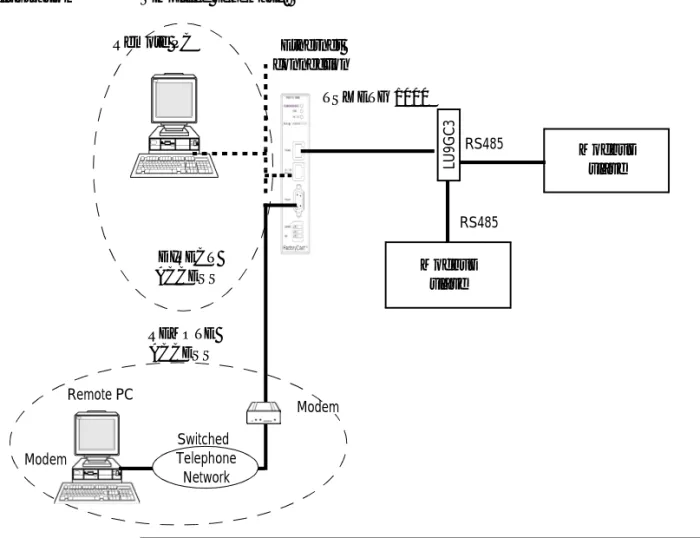
General The TSX ETG 1000 is a standalone TCP-IP/Modbus gateway module that can be
used to connect Modbus devices to a TCP-IP network. It is rated as class C20 (RT standard)
It is not inserted into a PLC rack.
The TSX ETG 1000 module can be configured using an embedded Web server. This is an external module which can be mounted on a DIN rail or on a Telequick pre-slotted plate.
It has a 24 VDC power supply and includes an RS232 serial link for connecting an external modem.
Illustration Simplified schematic:
TSX ETG 1000 Remote PC
Modbus slave Ethernet
connection
Remote PC
Modbus slave
LU
9GC3
Modem
RS485
RS485
Switched Telephone
Network
DIRECT ACCESS
REMOTE ACCESS
General Information about the TSX ETG Module
Presentation The TSX ETG 1000 module includes the following features:
l 24V DC power supply
l Ethernet 10/100 Base-T connection
l RS485 serial link for Modbus communication
l Modbus RTU master
l RS232 serial link for communication with an external modem or for configuration
l 3 LED indicators
l 8 MB of non-volatile Flash memory for backup of embedded software and website data
Module Services The following services are available:
l configuration via web pages, Ethernet or RS232 serial link,
l IP module setup either by configuration or automatically:
l BOOTP client,
l DHCP client: automatic reconfiguration on replacement of module (FDR function),
l secure access to default server without configuration, comprising:
l module configuration pages,
l diagnostic services,
l SNMP V1 service management with MIB-II agent and private Ethernet Transparent Factory MIB,
l Modbus messaging on TCP/IP with a maximum of 64 simultaneous connections,
l diagnostics via LED indicators,
l mail management initiated by Modbus register value on Modbus devices,
l up to 16 Internet browsers can be connected simultaneously,
l 8 MB of additional Flash memory reserved for the user application: the user can add custom pages or applets to the initial website,
l FTP server for loading client pages.
Summary of the Module Functions
At a Glance Various functions are available.
TSX ETG 1000 module
The table below summarizes the functions of the TSX ETG 1000:
Function Details
Messaging via Port 502 (Modbus on TCP/IP)
l A maximum of 64 simultaneous connections (Client +
Server)
l Access control via configuration table
Bootp client service
-DHCP (FDR) client service
-SNMP service l SNMP with MIB-II agent and Ethernet Transparent
Factory MIB
RS232 link for external modem l 4800, 9600, 19200, 38400 and 57400 baud
Modbus link l Configurable speed (1200, 2400, 4800, 9600, 19200,
38400, 57400 and 115200 baud), parity, stop bit, time-out
Email l Up to 8 alarms scanned
Website l Simultaneous connection of up to 16 Internet browsers
l Non-modifiable website, factory-installed, with configuration and diagnostics pages
3
Presentation
Scope of this Chapter
This chapter describes the services offered by the TSX ETG 1000 module.
What's in this Chapter?
This chapter contains the following sections:
Section Topic Page
3.1 Modbus Communication Function 24
3.2 TCP/IP Messaging 30
3.3 BOOTP and DHCP(FDR) Services 42
3.4 SNMP Server 47
3.5 SMTP Server 50
3.1
Modbus Communication Function
Presentation
Scope of this Section
This section describes the Modbus communication function via the TSX ETG 1000 module.
What's in this Section?
This section contains the following topics:
Topic Page
Modbus Communication 25
Modbus Communication
Principles The TSX ETG 1000 module is a TCP/IP/Modbus gateway for transmitting Modbus
requests.
The TSX ETG 1000 module is the Modbus master. In order for the gateway to operate as Modbus master, the module has to be connected to a Modbus slave device.
The Modbus link (speed, parity, address, etc) must be configured so that it is compatible with the slave link.
In Modbus, the TSX ETG 1000 module is always master. This means that exchanges between the module and a device on the bus are always made at the request of the module, which waits for a response from the device (slave) until it is received or until time-out. Only one exchange can be made at a time: if the module is waiting for a response from the device, it cannot send a request. TCP requests are suspended on the network (a maximum of 128 pending requests). The various devices can be assigned a Modbus address from 1 to 254. The TSX ETG 1000 module is the Modbus server accessible via address 255.
Modbus Parameters
The table below shows the parameters that have to be configured for the module:
Note: The TSX ETG 1000 module can only manage the Modbus RTU protocol (not Modbus ASCII).
Parameters Value
Baud rate Speed: 115200, 57600, 38400, 19200, 9600, 4800,
2400, 1200 baud
Data bits 8 data bits.
Stop bits 1 or 2 stop bits.
Parity Even, odd, or no parity.
Timeout In milliseconds, between 1 and 10 seconds (3
seconds by default).
Modbus Server
At a Glance The TSX ETG 1000 module includes a Modbus server.
It can be used to access internal module variable addressing (via Modbus TCP). To access the variables, the module address (UnitID) is 255.
The Modbus server manages the following requests:
l 03 ReadHoldingRegister,
l 16 WriteMultipleRegister,
l 43/14 ReadDeviceIdentification.
The compliance level of the ReadDeviceIdentification is regular with stream mode access and individual access.
Internal Module Registers
The TSX ETG 1000 module provides four register zones:
l User zone,
l Command zone
l Diagnostic zone
l Periodic zone
The user zone (registers 0 to 63).
This zone is available for unrestricted use. The user can read or write in this zone by means of Modbus TCP requests or by RDE/GDE (data table/graphics objects). This zone can be used in various ways:
l to send a mail from an Ethernet network
l to send a mail without a Modbus device: test email
l to store device values or to exchange values between devices
l to simulate a Modbus device,
l etc.
The command zone (register 500 to 511):
Register Description
500 Command status for register 501:
l = 0 for command not OK
l = FFFF for command in progress
l <> 0 for command not OK
501 Command:
l = 0 no command
l = 1 for alarm test service
l = 2 for open PPP connection
l = 3 for close PPP connection
502 Register 501 = 1 then number of alarm to be tested
502 to 505 Register 501 = 2 or 3 and IP address = 86.16.0.4 (for example) l Register 502 = 86 for the 1st value of the IP address l Register 503 = 16 for the 2nd value of the IP address l Register 504 = 0 for the 3rd value of the IP address l Register 505 = 4 for the 4th value of the IP address 506 to 511 Reserved.
The diagnostic zone (register 800 to 849) :
The periodic zone (registers 1000 to 1007):
Register Description
800 to 815 List of devices periodically scanned and present used by the alarms, 16 registers for 256 word bits = 1 bit per device.
816 to 819 Reserved.
820 Alarm service status (mail):
l = 2 for active l = 1 for inactive
l = 0 for not configured
821 Number of emails sent without error
822 Connection error counter at the SMTP server.
823 Number of Modbus requests sent by the ALARM service.
824 Number of Modbus responses for the ALARM service received without error.
825 Number of Modbus responses for the ALARM service received with error.
826 Email send error counter.
827 to 829 Reserved.
830 PPP connection status:
l = 2 for server connection
l = 1 for client connection
l = 0 for PPP inactive
831 to 834 PPP : IP address of remote device, if = 0 PPP line closed. 835 to 838 PPP : IP address of TSX ETG module, if = 0 PPP line closed. 839 to 842 IP address opened by a client PPP connection, if = 0 PPP line closed.
843 Number of PPP connections opened without error.
844 Number of errors on opening a PPP connection.
845 Number of PPP connections closed without error.
846 Number of errors on closing a PPP connection.
847 to 849 Reserved.
Register Description
1000 Value of register configured for alarm 1 for each scan.
1001 Value of register configured for alarm 2 for each scan.
1002 Value of register configured for alarm 3 for each scan.
1003 Value of register configured for alarm 4 for each scan.
1005 Value of register configured for alarm 6 for each scan.
1006 Value of register configured for alarm 7 for each scan.
1007 Value of register configured for alarm 8 for each scan.
Note: all these variables can be read and written as follows:
l via a Modbus TCP request using 255 as the device address
l via the module website data editor page or on custom pages (using 255 as the device address).
3.2
TCP/IP Messaging
Presentation
Scope of this Section
This section describes the TCP/IP messaging service available via the TSX ETG 1000 module.
What's in this Section?
This section contains the following topics:
Topic Page
Reminder of TCP/IP Features 31
IP Address 32
Sub-Addressing, Gateway 34
Connection Management 35
Opening a Connection on the Ethernet Network 36
Opening a Serial Link Connection via Modem 37
Closing a Connection 40
Reminder of TCP/IP Features
Communication Port
The communication port reserved for the TSX ETG 1000 module is Port 502 (port reserved for Schneider). When a client device wishes to access the module, it requests that a connection be opened to this port.
Time-Out on TCP Connection
If a TCP connection is unable to be established (destination unavailable, for example) the time-out for return of an error is 80 seconds.
We recommend setting the time-out for communication functions to a value greater than 80 seconds if the 1st exchange was unsuccessful.
"Keep Alive" Function
This function automatically generates a frame every 2 hours or so to check for broken connections. This mechanism is explained in more detail in this section.
IP Address
General Each device on the network must have a unique IP address.
The unique nature of the IP address is ensured by the attribution of a "network ID" by an approved body. The choice between the various classes depends on the number of networks in the installation and the number of devices to be connected.
Address Structure
Each IP address consists of two elements (network name and device identifier), where network name identifies a network (or a site) and where device identifier identifies a device connected to this network. There are three classes of IP address.
Address Classes The structure of the address classes is as follows:
Externally, a device's IP address is represented by a string of four 8-bit values (0 to 255), separated by dots: "a.b.c.d".
Default IP Address of the Ethernet Interface for the TSX ETG 1000 Module
The default IP address of the Ethernet interface for the TSX ETG 1000 module is constructed from its MAC address:
085.016.xxx.yyy where xxx and yyy are the last two numbers of the MAC address.
Example:
The MAC address of the module (in hexadecimal format) is: 00 80 F4 01 12 20. In this case the default IP address (in decimal format) is: 085.016.018.032.
Class First address of the class Last address of the class
A 0.0.0.1 127.255.255.254
B 128.0.0.1 191.255.255.254
C 192.0.0.1 223.255.255.254
0 Network identifier Device identifier
1 0 Network identifier Device identifier
1 0 Network identifier
1 Device identifier
7 bits 24 bits
14 bits 16 bits
21 bits 8 bits
Class A
Class B
IP Address of the PPP Interface
The TSX ETG 1000 module manages one IP address per interface:
l the IP address of the Ethernet interface, configured by the user or pre-assigned (see above)
l the IP address of the PPP interface
The latter is assigned when a connection is established by the PPP protocol. The TSX ETG 1000 module is configured to accept any type of IP address when a connection is being established. We therefore recommend that any device with which the TSX ETG 1000 module has to establish a modem/PPP connection is configured to assign the IP address to the TSX ETG 1000 module.
However, if the remote device is configured to receive its IP address from the TSX ETG 1000, the IP addresses once a connection has been established will be as follows:
l TSX ETG 1000: 85.16.0.2 l remote device: 85.16.0.1
If the connection is a TSX ETG 1000 <-> TSX ETG 1000 connection, both devices use the IP address 85.16.0.2 for their PPP interface.
Sub-Addressing, Gateway
Sub-Addressing The principle of sub-addressing is to divide the local part into a physical sub-network number and a device identification.
Illustration:
Mask A sub-network mask (Subnet Mask), coded in 32-bits, is used to define the bits of an IP address as the network part.
The mask bits are:
l Set to 1 if the bits corresponding to the IP address are to be interpreted as part of the network address
l Set to zero to identify the device
This system allows local internal networks to be addressed with a single attributed IP address.
Illustration:
Gateway The Gateway allows a message to be routed to a device which is not on the current
network.
Internet part = network Id Local part
Internet part Physical sub-network number
Device identification Format a
Format b
Internet part = network Id Local part
Internet part Physical sub-network number
Device identification Format a
Format b
Subnet(work)
Connection Management
At a Glance A connection can be opened by a remote device wishing to communicate with the
module in order to retrieve data via the Modbus. A connection is characterized by the module as follows:
Local TCP port, local IP address/remote TCP port, remote IP address.
The configuration screen can be used to configure the modem profile and the Ethernet profile.
Note: The maximum number of connections that can be open simultaneously is 64. The number of transactions managed by the TSX ETG 1000 is 128 for all port 502 connections.
Opening a Connection on the Ethernet Network
At a Glance A connection can be opened in one of the following ways:
l by request from a remote device,
l by request to a remote device.
Request from a Remote Device
In this case the TSX ETG 1000 is the connection server.
On receiving a connection request from a remote device, the IP address of the remote device is verified if and only if access control is enabled in the configuration. The test involves checking that this address is included in the list of remote devices authorized to connect. If that is the case, the connection is accepted, otherwise the connection is closed.
Opening a Serial Link Connection via Modem
Presentation A serial link connection via modem can be opened in one of the following ways:
l By request from a remote device (server mode)
l Or by email request from a module (client mode)
l Or by internal register command from a module (client mode)
PPP and PAP Protocols
The connection uses PPP (Point-to-Point Protocol). With this protocol, once a telephone connection has been established, the modem link is regarded at an application level as a TCP/IP link.
With a PPP connection, the identification protocol is PAP (Password Authentication Protocol). Any device with which the TSX ETG 1000 has a modem/PPP connection should be configured with the PAP protocol. The CHAP protocol is not implemented on the TSX ETG 1000.
In order for the connection to be accepted, you need to know the UserName and the
PAP Password for the remote device. Before connecting the TSX ETG 1000 to the remote device, you must also configure the remote device to use the PAP protocol. The password and the user name for the TSX ETG 1000 used by the PAP protocol are the same as those for the HTTP server (default: USER/USER).
The modem connected to the TSX ETG 1000 must respond to AT commands in ASCII mode.
Note: Client mode takes priority over server mode. If a remote device has established communication with the module in server mode, the connection will be closed by the TSX ETG 1000 if the module wishes to establish a connection to a remote device in client mode.
Note: Specialist line mode is not supported.
Connection by Request from a Remote Device
The TSX ETG 1000 is the connection server.
If the TSX ETG 1000 module is configured for use with a modem, the module listens for an incoming telephone connection request.
Once the telephone connection is established, the Username and Password (PAP) are verified. If identification is unsuccessful, PPP communication is not established. Illustration:
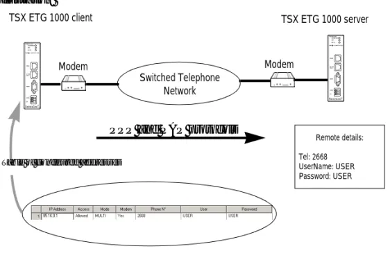
Connection by Request from a Remote Device
In this case the TSX ETG 1000 is the connection client. Two types of modem connection can be opened:
l The SMTP mail server is configured for modem connection; the module opens the connection automatically when an email is to be sent
l By register command from a module (see internal module register) (See Internal Module Registers, p. 27); in this case the connection is opened when the request is written
To open the connection, the module establishes a telephone connection by dialing the telephone number configured for this remote device.
The TCP/IP connection to port 502 on the remote device is then opened automatically by the TSX ETG 1000.
The remote device must be listed in the IP configuration table with its telephone number, name and password.
TM
Switched Telephone Network TSX ETG 1000 server
Modem Modem
Remote PC client
PPP and PAP protocols
TSX ETG details: Tel: 2668 UserName: USER Password: USER
Note: The email connection takes priority over the command; if the IP address is not the same, the email connection will close the current command. Otherwise the command will wait for the end of the email connection (during the wait the status assumes the value -1).
Illustration:
Note: Important: For a given remote device, the telephone number to be dialed can only be modified from the Setup menu on the Web server. The TSX ETG 1000 must then be restarted using the Reboot function in order for the new configuration to take effect.
Switched Telephone Network TSX ETG 1000 client
Modem Modem
TSX ETG 1000 server
PPP and PAP protocols Table of configured addresses
Remote details: Tel: 2668 UserName: USER Password: USER
TM TM
Closing a Connection
At a Glance A TCP/IP connection can be closed in one of two ways:
l by the remote station if it decides to end communication and send a TCP/IP connection cutoff,
l by the TSX ETG 1000; if the maximum number of open connections has been reached, the oldest open connection is closed.
When a connection is closed, it is signaled to the application by an error report (message rejected) as soon as an exchange is initiated.
In the case of a telephone connection, the connection is broken:
l by the remote station if it decides to end communication and hang up the telephone connection,
l if the remote device is not authorized to connect,
l if the time between two frames defined during configuration elapses,
l if the connection time exceeds the time defined during configuration (See Configuration Parameters for TCP/IP Services, p. 108),
l if a module acting as remote station server wants to establish a connection to another remote station in client mode via modem,
l if an email connection is terminated and a command (override on module command register) is sent by the device.
Behavior when a Connection is Broken
Presentation A broken connection can take one of two forms:
l Disconnection of the network cable (cable unplugged, broken, etc.)
l Disappearance of the remote device (device failure, power outage, etc.) The loss of connection is detected after 2 hours by the Keep Alive request. If the connection is reestablished during this time, the restoration of communications depends on the way in which the connection was broken.
Cable Reconnection
In this case the connection was broken due to a network cable, but the two stations are still operational.
When the cable is reconnected, communication between the TSX ETG 1000 module and the remote device is resumed on the open TCP/IP connection.
Remote Device as Server
The remote device that disappeared was acting as server.
1 The client TSX ETG 1000 module continues to send data on the old connection (that
remains partly open).
2 The server receiving data with no associated connection sends a Reset command and
closes the old connection.
3 The client TSX ETG 1000 module opens a new connection.
Remote Device as Client
The remote device that disappeared was acting as client.
1
2
3
Remote device
Server Client
TSX ETG
1 2 Remote device
Client
Server
3.3
BOOTP and DHCP(FDR) Services
Presentation
Scope of this Section
This section describes the BOOTP and DHCP(FDR) services.
What's in this Section?
This section contains the following topics:
Topic Page
BOOTP/DHCP(FDR) Services - General 43
TSX ETG 1000 as BOOTP Client 44
BOOTP/DHCP(FDR) Services - General
Presentation The TSX ETG 1000 module can be configured directly with its Ethernet interface IP address in the FDR Client page or using an automatic configuration protocol. These protocols are: BOOTP and DHCP.
BootP (Bootstrap Protocol) and DHCP (Dynamic Host Configuration Protocol) are protocols for booting diskless terminals or stations using centralized management of network parameters.
Their main purpose is to provide an IP address or a configuration to a station booting on the network.
The TSX ETG 1000 is the BOOTP client or DHCP client.
The BOOTP/DHCP server can therefore be a Premium fitted with a TSX ETY module or a Quantum fitted with an NOE module.
Note: Automatic configuration only works with an Ethernet connection and not with an RS232 or modem connection.
TSX ETG 1000 as BOOTP Client
Principle The principle used is as follows:
l The TSX ETG 1000 module requests an IP configuration (IP address, subnet mask, gateway) from a BOOTP server by means of its MAC address.
l The BOOTP server uses a MACAddress/IP Configuration correspondence table to return the IP configuration to the TSX ETG 1000.
Initial Startup Behavior of the TSX ETG 1000 module on initial startup:
The TSX ETG 1000 module sends a configuration request to the server:
l If the module is not recognized, it starts up with its default IP configuration (factory-set)
l If the BOOTP server sends an IP configuration, the TSX ETG 1000 uses it but
without storing it in Flash memory.
Subsequent Startups
Behavior of the module on subsequent startups:
The TSX ETG 1000 module sends a configuration request to the server:
l If the BOOTP server sends a configuration, the TSX ETG 1000 uses it.
l If the BOOTP server does not respond within about 5 minutes, the
TSX ETG 1000 module switches to downgraded operating mode and uses the IP configuration stored in the Flash memory (the factory-set default configuration).
Note: Important: In order to use the BOOTP service, you must configure the address server as BOOTP server and identify the client device by its MAC address.
Note: The BOOTP server only returns the IP address, the subnet mask and the gateway; the other data can be found in the configuration page.
TSX ETG 1000 as DHCP(FDR) Client
At a Glance This service allows the automatic retrieval of IP, Modbus, SNMP and email
configurations by a TSX ETG 1000 module connected to an Ethernet segment with Transparent Factory.
The FDR function uses a combination of the DHCP and FTP/TFTP protocols. The TSX ETG 1000 uses a name (Device Role Name) to obtain its configuration from the server. The Device Role Name is a string of characters (maximum of 15) associated with the module that must be unique within the architecture.
The TSX ETG 1000 is therefore able to configure itself automatically using a parameters file previously saved in the DHCP server, for example a Premium TSX ETY 5102 module.
Operation The operating principle of the FDR service is as follows:
Note: In order to use the FDR service, you must configure the address server (e.g. TSX ETY 4102/5102) as DHCP server and identify the client device by its Role Name. When configured as FDR server, the TSX ETY 4102/5102 can manage a maximum of 16 TSX ETG 1000 clients.
Note: Passwords are not stored in the server. The passwords retrieved will therefore be default passwords.
1 A TSX ETG is connected to the network with a configured name (Device Role Name).
2 The TSX ETG sends a DHCP request, indicating its associated Device Role Name.
3 If the Device Role Name is included in the DHCP server's configuration table, the
server sends the following to the module: l the IP address that it must use
l the IP address of the FTP/TFTP server
l the location of the configuration file for retrieval from the FTP/TFTP server
4 The TSX ETG 1000 then accesses the FTP/TFTP server to upload or download the
Initial Startup Behavior of the TSX ETG 1000 module on initial startup:
The TSX ETG 1000 module sends a configuration request to the server:
l if the module is not recognized, it starts up with the default configuration (factory-set) after approximately 5 minutes.
l if the module is recognized, the TSX ETG 1000 starts up with the configuration provided and stores it in its Flash memory (according to the IP configuration).
Subsequent Startups
Behavior of the module on subsequent startups:
The TSX ETG 1000 module sends a configuration request to the server:
l If the module is recognized, the TSX ETG 1000 starts up with the configuration provided and stores it in its Flash memory (according to the IP configuration).
l If the module is not recognized, it starts up after approximately 5 minutes with the default configuration based on its MAC address.
3.4
SNMP Server
SNMP Communication in UDP/IP
At a Glance The SNMP standard (Simple Network Management Protocol) defines network
management solutions in terms of protocol and supervised data exchange. The SNMP architecture is based on the following key elements:
l the Manager is used to supervise all or part of the network,
l one or more Agents. Each device being supervised has a software module called an Agent used by the SNMP protocol,
l an MIB (Management Information Base) is a database or collection of objects updated by the agents.
The SNMP agent service is implemented on the TSX ETG 1000 module. The SNMP protocol allows a Manager to access standard MIB objects in the TSX ETG 1000 module.
The MIB-II is used to manage TCP/IP communication layers.
The MIB Ethernet Transparent Factory allows a Manager to access data on the messaging service on port 502.
View of the Ethernet Transparent Factory MIB tree via a Manager: experimental
private enterprises
schneidergroup
transparentFactoryEthernet switch
port502Messaging ioScanning globalData web addressServer deviceProfile
The SNMP Protocol
The SNMP protocol defines 5 types of message between agent and manager: these messages are stored in UDP datagrams.
Messages from the manager to an agent:
l Get_Request: message used to obtain the value of one or more variables
l Get_Next_Request: used to obtain the value of subsequent variables
l Set_Request: used to position the value of a variable
Messages from an agent to the manager:
l Get_Response: used by the agent to return the variable value requested
l Trap: used by the agent to signal an event to the Manager (unauthorized access attempt or rebooting of the device)
Description of Services
The SNMP manager sends write or read requests (Set_Request, Get_Request,
Get_Next_Request, etc.) for objects defined in the SNMP MIB-II, and the SNMP
agent for the TSX ETG 1000 module responds.
The module's SNMP agent sends events (Traps) to the Manager. The following System Traps are managed:
l Coldstart Trap:
l The event is only sent when the module is powered up
l Authentication Failure Trap: event sent after an authentication problem.
The Community Name field in the message received is different from that configured on the module. This trap can be validated when the TSX ETG 1000 module is configured.
Get_Response Trap
Set_Request Get_Request Get_Next_Request
SNMP Agent TSX ETG 1000
3.5
SMTP Server
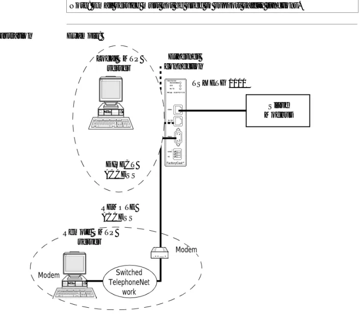
General The TSX ETG 1000 module provides an email function. The sending of emails is
initiated by the scanning of Modbus device registers or of internal module registers. The SMTP server address must be configured; this server can be connected either via the Ethernet or via a modem.
Illustration Example:
Note: Email service must not be used to support safety functions.
TM
TSX ETG 1000
Slave Modbus Ethernet
connection
Modem Switched
TelephoneNet work
REMOTE ACCESS
Modem
Remote SMTP server
Local SMTP server
DIRECT ACCESS
The modem connection is established automatically when an email is to be sent. This connection takes priority and can interrupt all other modem connections established by a remote device or by a module register command.
Note: It is possible to test the sending of an email (alarm) using the register command (See Internal Module Registers, p. 27) or by clicking Test email (See Test Email Page, p. 65) in the Diagnostics menu to initiate one of the configured alarms.
3.6
HTTP Server
Presentation
Scope of this Section
This section describes the HTTP server included with the TSX ETG 1000 module.
What's in this Section?
This section contains the following topics:
Topic Page
Embedded HTTP Server 53
Home Page for the HTTP Server 56
TSX ETG 1000 Version Page 58
Diagnostics Home Page 59
Ethernet Statistics Page 61
Modbus Statistics Page 62
Email Statistics Page 63
Test Email Page 65
PPP/Modem Statistics Page 66
RS232 Modem Connection Diagnostics Page 68
Statistics Page for Faulty Device Replacement - FDR 70
MIB Upload Page 72
TSX ETG 1000 Setup Home Page 73
Security Page 75
TCP/IP Services Configuration Page 77
Modbus Connection Configuration Page 78
Automatic Configuration Page 79
SNMP Function Configuration Page 80
SMTP Function Configuration Page 81
Alarm Configuration Page 82
Module Reboot Page 83
Monitoring Pages for the TSX ETG 1000 84
Data Viewer Page 85
Data Editor Page 87
Embedded HTTP Server
At a Glance TSX ETG 1000 modules are provided as standard with a web server which can be
used:
l to configure the module:
l TCP/IP parameters,
l modem,
l Modbus parameters,
l SNMP,
l SMTP,
l to change the user name and password for accessing the site,
l to access PLC or device data,
l to assign a Device Role Name if automatic configuration has been chosen. The functions provided by the website require no configuration or pre-programming of the module.
All the server data is constructed in the form of standard web pages in HTML format. These pages can be viewed with an Internet browser.
Module functions:
Functions TSX ETG 1000
Number of browsers connected 16 max.
Website embedded as standard Yes
Default Web Server Functions
The following functions are available:
l module diagnostic functions:
l Ethernet and Modbus network statistics,
l statistics and email test,
l RS232 modem connection statistics and diagnostics via log file,
l FDR statistics,
l MIB upload,
l module setup functions:
l security or password change,
l TCP/IP and Modbus parameter configuration,
l FDR client configuration,
l SNMP and SMTP parameter configuration,
l alarm configuration,
l module rebooting,
l module monitoring functions:
l reading and editing Modbus device or module data,
l monitoring custom graphic pages.
Note: The page loading progress bar (functions or services) is only visible if the browser is using Java version 1.4 or later from SUN.
HTTP Connections
The following connection rules must be observed:
l 1 connected Internet browser can open 2 connections, and the TSX ETG 1000 allows a maximum of 32 connections,
l each HTTP connection closes automatically after one minute of inactivity,
l the connection remains active when passwords are being entered.
This means that up to 16 Internet browsers can be connected to one TSX ETG 1000 module.
When the maximum number of HTTP connections is reached, the following screen is displayed:
e 503 Service Unavailable - Microsoft Internet Explorer
File Edit View Favorites Tools ?
Links
Address http://192.168.2.14
Back Forward Stop
X
Refresh Home Search
e
Internet
e Done
e
Maximum number of connections has been
exceeded
Please try again later!!!
>> >>
Home Page for the HTTP Server
Presentation This page is the website home page. It is used to access the service pages on the site:
l The module diagnostics access page: Diagnostics l the Monitoring page
l the module configuration access page: Setup
Accessing the Home Page
The procedure below shows how to access the website home page.
Note: On this home page you can also choose the language you wish to use to navigate the various service pages and determine the product version.
Step Action
1 Open your usual browser.
Illustration The TSX ETG 1000 home page looks like this:
Note: The Documentation link allows you to access and open product documentation in HTML format.
Home Documentation
Monitoring Control Diagnostics Maintenance Setup
FactoryCast TSX ETG 1000
TMa brand of
Schneider
Electric
Internet
Home Language
Product
English French Version About
Telemecanique
Web site version: 1.0.0.0
TSX ETG 1000 Version Page
At a Glance This page gives the version of the TSX ETG 1000 module.
Illustration The TSX ETG 1000 version page is shown below:
Home Documentation
Monitoring Control Diagnostics Maintenance Setup
FactoryCast TSX ETG 1000
TMa brand of
Schneider
Electric
Internet
Home Languages
Product
English French Version About
Telemecanique
© 2000-2004 Schneider Electric. All Rights Reserved Version: TSX ETG 1000 V1. 0 .4
Diagnostics Home Page
Home Page This page lists the various diagnostic services supported by the web server of the TSX ETG 1000 module and provides links for accessing the service you require.
Accessing the Diagnostics Page
To access the Diagnostics page, follow the steps below:
Step Action
1 Click the Diagnostics link on the Home page. Click one of the services offered
on the Diagnostics home page.
2 Result: a window opens, asking for your user name and password. Enter your user name and password (these fields are case-sensitive).
Note: The default values are as follows:
l user name: USER
l password: USER
Illustration The Diagnostics home page looks like this:
To access the service you require, click on one of the following links:
l Ethernet statistics to find out about managing the diagnostics counters for Ethernet communications,
l Modbus statistics to find out about managing the diagnostics counters for messaging, timeout and CRC counters for Modbus messages,
l email Statistics to find out about managing the diagnostics counters for messaging,
l email test to simulate sending alarms by email,
l PPP statistics to find out about managing diagnostic and IP address counters for PPP communications,
l log file to view the modem connection log file,
l FDR statistics to find out about managing the diagnostic parameters and counters for the FDR service(Faulty Device Remplacement),
l MIB upload to upload the module MIB (Management Information Base) onto the PC.
Diagnostics
Ethernet Statistics
Statistics Test
PPP/Modem
Statistics Log File FDR Statistics MIB Upload Modbus Statistics
Home Documentation
Monitoring Control Diagnostics Maintenance Setup
FactoryCast TSX ETG 1000
TMInternet
Telemecanique
Web site version: 1.0.0.0
© 2000-2004 Schneider Electric. All Rights Reserved
a brand of
Schneider
Ethernet Statistics Page
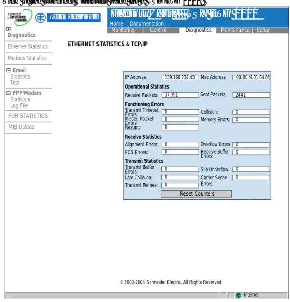
At a Glance This page provides statistics about the Ethernet network. It can be used to perform diagnostics on a network.
Illustration View of the Ethernet Statistics page for a TSX ETG 1000:
Reset Counters IP Address: 0 139.160.234.43 37 391 0 0 0 0 0 0 0 0 0 0 0 0 0 2441 00.80.f4.01.64.6f Receive Packets: Operational Statistics Functioning Errors Receive Statistics Transmit Statistics Transmit Timeout Errors: Missed Packet Errors: Restart: Alignment Errors: FCS Errors: Transmit Buffer Errors: Late Collision: Transmit Retries: Silo Underflow: Carrier Sense Errors: Overflow Errors: Receive Buffer Errors: Collision: Memory Errors: Sent Packets: Mac Address Diagnostics Email Ethernet Statistics Statistics Test PPP/Modem Statistics Log File FDR STATISTICS MIB Upload Modbus Statistics Home Documentation
Monitoring Control Diagnostics Maintenance Setup
FactoryCast TSX ETG 1000
TM Telemecaniquea brand of
Schneider
Electric
Modbus Statistics Page
At a Glance This page provides statistics about the Modbus network. It can be used to perform diagnostics on a network.
It provides access to the following counters:
l number of frames sent
l Number of frames received
l number of Modbus requests received with no response
l number of responses received with CRC errors
Illustration View of the Modbus Statistics page for a TSX ETG 1000:
Diagnostics
Ethernet Statistics
Statistics Test
PPP/Modem
Statistics Log File FDR STATISTICS MIB Upload Modbus Statistics
Home Documentation
Monitoring Control Diagnostics Maintenance Setup
FactoryCast TSX ETG 1000
TMInternet
Telemecanique
© 2000-2004 Schneider Electric. All Rights Reserved
a brand of
Schneider
Electric
MODBUS STATISTICS SERIAL LINK
3612
Reset counters
sent frames:
Receiver Statistics
Received frames:
Timeout errors:
CRC errors:
3648
36
0 Transmitter Statistics
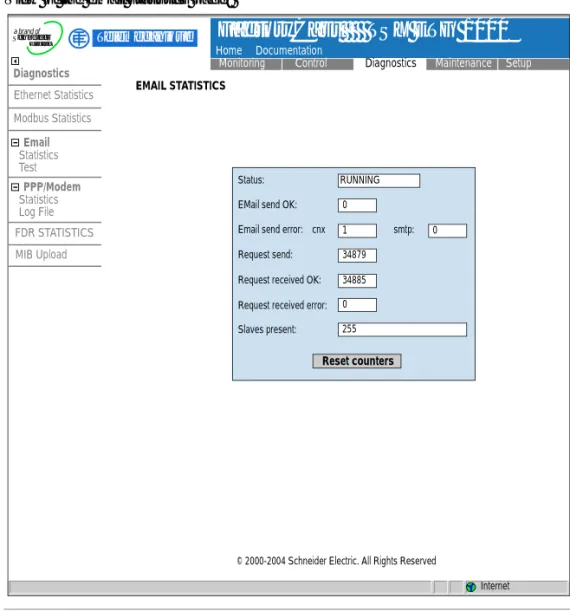
Email Statistics Page
At a Glance This page can be used to view the status of the email service.
Illustration View of the email statistics page:
RUNNING
Reset counters
Status:
EMail send OK:
Email send error:
Request send:
Request received OK:
Request received error:
Slaves present: 0 1 34879 34885 0 255 0 smtp: cnx Diagnostics Email Ethernet Statistics Statistics Test PPP/Modem Statistics Log File FDR STATISTICS MIB Upload Modbus Statistics Home Documentation
Monitoring Control Diagnostics Maintenance Setup
FactoryCast TSX ETG 1000
TMInternet
Telemecanique
© 2000-2004 Schneider Electric. All Rights Reserved
a brand of
Schneider
Electric
Parameters Description of parameters:
Text Description
Status Indicates the status of the email function:
l Not configured: no alarms declared in the alarm configuration page,
l Inactive: alarms declared but actions disabled (Enable alarms: unchecked in the alarm configuration page),
l Running: alarms declared and action enabled (Enable
alarms selected in the alarm configuration page).
Email send OK Number of alarms sent without error.
Email send error cnx Number of alarms sent with problem connecting to SMTP server.
Email send error smtp Number of alarms sent with SMTP protocol error. Email received OK Number of responses to Modbus requests received
without error.
Email received error OK Number of responses to Modbus requests received with error.
Slaves present List of Modbus slaves present (configured in the alarm configuration page).
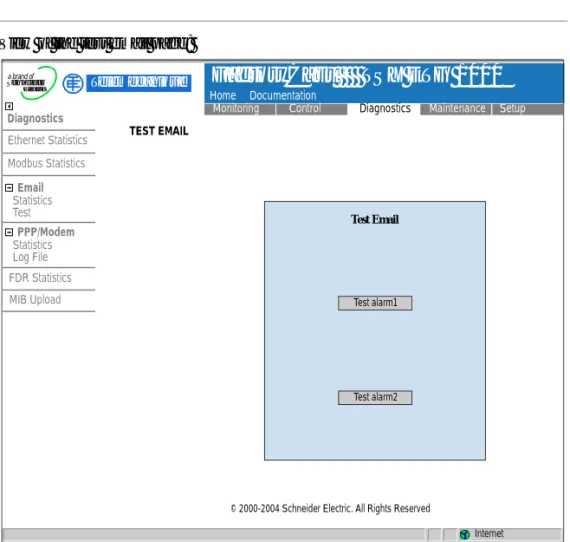
Test Email Page
At a Glance This page can be used to test the sending of an email with just one click.
Illustration View of the test email page:
Note: Before it can be used, you must configure at least one alarm in the alarm configuration page.
Test Email
Test alarm1
Test alarm2
Diagnostics
Ethernet Statistics
Statistics Test
PPP/Modem
Statistics Log File FDR Statistics MIB Upload Modbus Statistics
Home Documentation
Monitoring Control Diagnostics Maintenance Setup
FactoryCast TSX ETG 1000
TMInternet
Telemecanique
© 2000-2004 Schneider Electric. All Rights Reserved
a brand of
Schneider
Electric
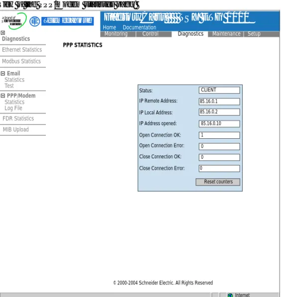
PPP/Modem Statistics Page
At a Glance This page can be used to view PPP/modem statistics.
Illustration View of the PPP/modem statistics page:
CLIENT
Reset counters Status:
85.16.0.1 85.16.0.2
85.16.0.10
1
0 0
0 IP Remote Address:
IP Local Address: IP Address opened:
Open Connection OK: Open Connection Error: Close Connection OK:
Close Connection Error:
Diagnostics
Ethernet Statistics
Statistics Test
PPP/Modem
Statistics Log File FDR Statistics MIB Upload Modbus Statistics
Home Documentation
Monitoring Control Diagnostics Maintenance Setup
FactoryCast TSX ETG 1000
TMInternet
Telemecanique
© 2000-2004 Schneider Electric. All Rights Reserved
a brand of
Schneider
Electric
Parameters Description of parameters:
Text Description
Status Indicates the status of the PPP connection:
l inactive if there is no connection, l server if there is a remote connection,
l client if the TSX ETG 1000 is connected (command or
sending email).
IP remote address IP PPP address of the remote connection. If the PPP
connection is closed IP=0.0.0.0.
IP local address PPP IP address of the local connection (module). If the
PPP connection is closed IP=0.0.0.0.
IP address opened Current IP address opened for the PPP connection (for
client connections only). If the PPP connection is closed IP=0.0.0.0.
Open connection OK Number of PPP connection opened without error.
Open connection error Number of PPP client connection opened with error (IP
address error, no response from modem, line busy, etc.).
Close connection OK Number of PPP connection closed without error.
Close connection error Number of PPP client connection closed with error (IP
RS232 Modem Connection Diagnostics Page
At a Glance This page can be used to perform diagnostics on the RS232 Modem connection.
Illustration View of the PPP/Modem Log File page:
Diagnostics
Ethernet Statistics
Statistics Test
PPP/Modem
Statistics Log File FDR Statistics MIB Upload Modbus Statistics
Home Documentation
Monitoring Control Diagnostics Maintenance Setup
FactoryCast TSX ETG 1000
TMInternet
Telemecanique
© 2000-2004 Schneider Electric. All Rights Reserved
a brand of
Schneider
Electric
**************************************** ETG1000 PPP/Modem Log File ---****************************************
---Modem connection configured RS232 link down
---Dial phone number ... Remote Modem connection OK
PPP Client Connected on Remote network PPP Client: IP Remote Address: 85.16.0.1 PPP Client: IP Remote Network: 85.0.0.0 PPP Client: IP Local Address: 85.16.0.2 PPP Link down
---Modem connection configured
Description This page displays a text file showing a log of the last four connections. The following reports can be displayed:
Text Meaning
Dial phone number... The modem is dialing the remote telephone
number.
No Remote Modem Answer The remote modem is not responding.
Remote Modem connection OK The modem connection has been
established.
Phone line busy The remote modem is already connected.
Phone Line Error Faulty connection on the phone line.
No Modem Answer The local modem is not responding.
PPP Client Connected on Remote Network The local client has connected to a network or
a remote station.
PPP Client: IP Remote Address: xx.xx.xx.xx IP address of the station called.
PPP Client: IP Remote Network: xx.xx.xx.xx IP network number of the station called.
PPP Client: IP Local Address: xx.xx.xx.xx Local IP address of the station that is calling.
PPP Client Connection Error No PPP connection has been established
(password or IP address problem).
Direct cable connection configured The RS232 connection is ready for a cable
connection.
Modem connection configured A modem connection has been configured.
PPP server ok A call from a remote station has been
established.
PPP server: IP Remote Address IP address of the remote station that is calling.
PPP server: IP Local Address Local IP address of the station.
RS232 lind down Communication interrupted (cable
disconnected, etc.).
Caution: this report is normal before the modem dials the remote number (Dial phone number).
PPP connection timeout expired Connection timeout detected, communication
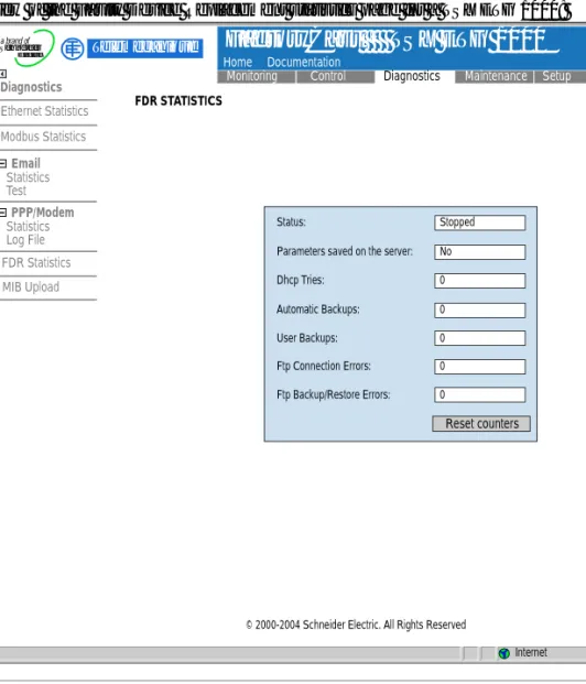
Statistics Page for Faulty Device Replacement - FDR
At a Glance This page can be used to perform diagnostics on the Faulty Device Replacement
(FDR) function.
Illustration View of the Faulty Device Replacement statistics page for a TSX ETG 1000:
Stopped
No
0
0
0
0
0
Reset counters
Status:
Parameters saved on the server:
Dhcp Tries:
Automatic Backups:
User Backups:
Ftp Connection Errors:
Ftp Backup/Restore Errors:
Diagnostics
Ethernet Statistics
Statistics Test
PPP/Modem
Statistics Log File FDR Statistics MIB Upload Modbus Statistics
Home Documentation
Monitoring Control Diagnostics Maintenance Setup
FactoryCast TSX ETG 1000
TMInternet
Telemecanique
© 2000-2004 Schneider Electric. All Rights Reserved
a brand of
Schneider
Electric
Parameters Description of parameters:
Text Description
Status Indicates the status of the FDR function:
l Starting, Running, Stopped, Error.
Parameters saved on server Parameters saved on server:
l Yes, No.
This information is only relevant if the FDR function is enabled.
Dhcp Tries Total number of DHCP tries.
Automatic Backups Total number of successful automatic backups of the
TSX ETG 1000 configuration to the server.
User Backups Total number of successful backups of the
TSX ETG 1000 configuration to the server, initiated by the user by means of the button on the Force Backup of the Client FDR (See Command Area, p. 112) page.
Ftp Connections Errors Number of failed FTP connections in FDR mode. This
error counter shows FTP errors other than configuration file write or read errors.
Ftp Backup/Restore Errors Number of failed configuration file backup or restore
MIB Upload Page
Presentation This page is used to upload the MIB of the TSX ETG 1000 to a PC connected to the module.
TSX ETG 1000 Setup Home Page
Home Page This page lists the various setup services supported by the default web server of the TSX ETG 1000 module and provides links for accessing the service you require.
Accessing the Setup Page
To access the setup page, click Setup. You will be asked to enter your user name and password to access the services (default is USER).
Illustration The Online Setup home page looks like this:
To access the service you require, click one of the links.
l Security to configure user name or password
l Modbus to configure the Modbus serial connection
l IP/PPP to configure IP and PPP services
l FDR Client to configure the choice of BootP or DHCP
l SNMP to configure the SNMP service
l SMTP to inform the SMTP server module
l Alarms to configure remote email alarms
l Reboot to reinitialize the module Setup
Security Modbus IP/PPP FDR Client SNMP SMTP Alarms Reboot
Home Documentation
Monitoring Control Diagnostics Maintenance Setup
FactoryCast TSX ETG 1000
TMInternet
Telemecanique
Web site version: 1.0.0.0
© 2000-2004 Schneider Electric. All Rights Reserved
a brand of
Schneider
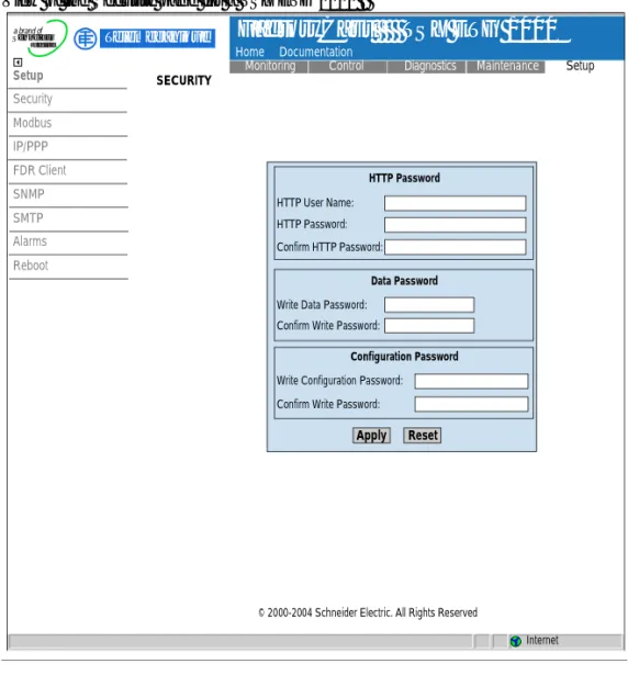
Security Page
Presentation For HTTP access, this page allows you to change:
l The user name and password to access the home page
l The password for writing variables to the data editor
l The password for accessing the configuration parameters
The maximum length of the user name and password is 15 characters (a-z, A-Z and 0-9).
The default values for the Username/Password fields protecting Web page access are USER/USER.
Illustration View of the Security page for a TSX ETG 1000 :
Apply Reset
HTTP Password
Data Password
Configuration Password HTTP User Name:
HTTP Password: Confirm HTTP Password:
Write Data Password: Confirm Write Password:
Write Configuration Password: Confirm Write Password:
SECURITY
Setup
Security Modbus IP/PPP FDR Client SNMP SMTP Alarms Reboot
Home Documentation
Monitoring Control Diagnostics Maintenance Setup
FactoryCast TSX ETG 1000
TM Telemecaniquea brand of
Schneider