http://dx.doi.org/10.4236/cs.2016.710288
An Optimal Control Theory Based Analysis
of Brushless DC Motor Drive
Murugan Marimuthu
1, Jeyabharath Rajaiah
21K. S. Rangasamy College of Technology, Tiruchengode, India
2K. S. R. Institue for Engineering and Technology, Tiruchengode, India
Received 5 May 2016; accepted 15 May 2016; published 31 August 2016
Copyright © 2016 by authors and Scientific Research Publishing Inc.
This work is licensed under the Creative Commons Attribution International License (CC BY). http://creativecommons.org/licenses/by/4.0/
Abstract
The application of BLDC motor drives in industries is becoming more popular nowadays. An error will occur in the drive that is originated by some disturbances which are the major problems to reduce the stability of the system. To obtain the minimum performance index, the optimal control signal is formulated, which is the main objective of this paper. Based on quadratic performance index, the optimal control system of BLDC motor drive is a design which spotlights in this paper. The complexity of the mathematical expressions has been reduced by using state space approach to the BLDC system. The burden to the control engineers has reduced based on tedious computa-tion by using thus optimal design. To provide the desired operating performance, this optimal de-sign helps to realize the BLDC system with practical components.
Keywords
BLDC Motor, Optimal Control, Performance Index, Stability Analysis and State Variables
1. Introduction
Due to change in load variations, BLDC motor exhibits oscillations in speed response and hence the stability of the system gets affected. The stability issues can be recovered by two ways, namely reducing the gain of speed controller and regulating output method [3]-[5]. But reducing the gain increases the oscillations and de-creases the system performance. The regions of instability occur due to changes in the reference input command. Because of oscillations in the output of BLDC motor, it cannot achieve precise speed control. In the next method of regulating the system output modification cannot achieve the time optimal operation [6]-[8]. In the classical design method of control systems, the designer is given a set of specifications in time domain or in frequency domain with the system configuration. In practice, it may not be possible to satisfy all the desired specifications
[9]-[11]. The optimal control design is aimed at obtaining a best possible system of a particular type with respect to a certain performance index or design criterion. The optimal control problem of systems has always been the key focus of control fields in the past several decades. The optimal control approaches are mostly based on li-nearization methods or numerical computation methods [12] [13].
The optimal control design is aimed to obtain a best possible system of a particular type with respect to a cer-tain performance index. In the optimal control design, the performance index replaces the conventional design criteria. A transfer function for the BLDC drive is derived in this paper. In this paper, for digitally PWM con-trolled BLDC motor drive, the optimal control system is designed. To achieve this optimization, the state and control variables are formulated in this paper. Based on optimal control theory, the BLDC performance charac-teristics close to the optimal control system are synthesized.
2. Digital PWM Control of BLDC Motors
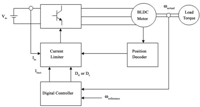
By changing the applied voltage across the motor phases, the speed of BDC motor can be controlled. This is achieved by utilizing pulse amplitude modulation, PWM or hysteresis control. Another method of speed control involves sensorless techniques.Figure 1 shows the block diagram for digital PWM control for a BLDC motor drive system. The derivation of this model is based on the assumption that the induced currents in the rotor due to stator harmonic fields are neglected and the iron and stray losses are also neglected [4].
The torque equation is given by,
d d
em L
T J B T
t
ω
ω
= + + (1)
where Tem, ω(t), B, J and TL denote electromagnetic torque, rotor angular velocity, viscous friction constant, ro-tor moment of inertia and load ro-torque respectively.
em
[image:2.595.116.511.491.702.2]T
α
I (2)em t
T =k I (3) d
d
t L
k I J B T
t
ω
ω
= + + (4)
where Kt = torque constant and I = average current. For the purpose of analysis, the digital controller was consi-dered equivalent to a proportional controller with high gain and saturation.
From the above equations it is possible to derive the transfer function
( )
( )
2t
a
a a a t
a a
K
s JL
V s JL BL BR K K
s s
JL JL
ω
∞ =
+ +
+ +
(5)
The state variable equation for this BLDC drive is given by 1 2
2 1 2
a t e a a t
a a a
x x
BR k k JR BL k
x x x u
JL JL JL
=
+ +
= − − +
(6)
Arranging in matrix form, the following equations are obtained
(
)
(
)
1 1
2 2
0 1 0
t
a t e a a
a
a a
x x
u k
BR k k JR BL
x x
JL
JL JL
=− + − + +
(7)
The output equation is given by,
[
]
12 1 0 x y
x
=
(8)
3. State Variable Feedback
The design of a state feedback BLDC motor control system is based on a suitable selection of a feedback system structure. If the state variables are known, then they can be utilized to design a feedback controller so that the input becomes u = kx. It is necessary to measure and utilize the state variables of the system in order to control the speed of the BLDC motor. This design approach of state variable feedback control gives sufficient informa-tion about the stability of the BLDC drive system. Feedback control system will be chosen so that,
( )
1 1 2 2u t = −k x −k x (9) Then Equations (6) & (7) become,
1 2
1 2
2 1 2
a t e t a a t
a a
x x
BR k k k k JR BL k k
x x x
JL JL
=
+ + + +
= − −
(10)
Arranging in matrix form the following state equation is obtained
(
)
(
)
1 1
1 2
2 2
0 1
a t e t a a t
a a
x x
BR k k k k JR BL k k
x x
JL JL
= − + + − + +
(11)
This is in the form x=Hx
where
(
1)
(
2)
0 1
a t e t a a t
a a
H BR k k k k JR BL k k
JL JL
= − + + − + +
Let k1=1 and determine a suitable value for k2 so that the performance index is minimized.
( )
( )
T T
0
d 0 0
J X X t X PX
∞
=
∫
= (13)T
H P+PH= −I (14)
(
)
(
)
(
)
(
)
1
11 12
12 22 2
11 12
1 2
12 22 0
1
0 1
1 0
0 1
a t e t
a
a a t
a
a t e t a a t
a a
BR k k k k
JL P P
P P
JR BL k k
JL
P P
BR k k k k JR BL k k
P P
JL JL
− + +
− + +
−
+ + + − + + =
−
(15)
Completing matrix multiplication, addition and solving the following are obtained
(
)
(
)
(
(
2)
)
11
2
2 2
a a t e t a a t
a a t a t e t
JR BR k k k JR BL k k
P
JR BL k k BR k k k
+ + + + +
= +
+ + + + (16)
(
)
12 2
a
a t e t
JR P
JR k k k
=
+ + (17)
(
)
(
)(
)
22
2 2
a a a t e t
a a e t a t e t
JL JL BR k k k
P
JR BL k k k BR k k k
+ + +
=
+ + + + + (18)
11 2 12 22
J=P + P +P (19) To minimize as a function of k2
2 0 J k
∂ =
∂ (20) Therefore,
(
) (
2)
2 2t 2 2
2
k 2
a a a a t e a a
a a
t t
JR BL JL BR k k J Ra JR BL B La
JR BL k
K k
− + + + + + +
−
= ± (21)
2 1.01499
k = (22) min 1.47
J = (23) The system matrix H obtained for the compensated system is,
0 1
2629.476 2833.7
H =
− −
(24)
The feedback control signal is obtained as,
1 1.015 2
u= − −x x (25) This optimal controlled BLDC drive system results in a minimum value for the performance index. Also, the control law given by Equation (25) yields optimal result for any initial state under the given performance index. This design based on the quadratic performance index yields a stable control system for the BLDC drive system.
4. Optimal System with Control Energy Considerations
expenditure of the optimal energy of the performance index T T
( )
( )
0d 0 0
J X X t X PX
∞
=
∫
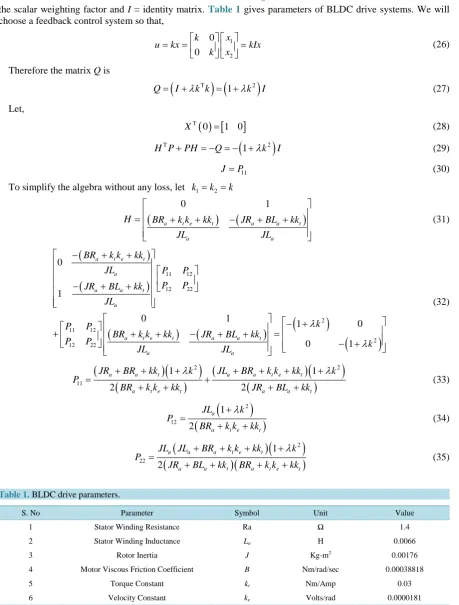
= is chosen where λ is the scalar weighting factor and I = identity matrix. Table 1 gives parameters of BLDC drive systems. We will choose a feedback control system so that,1 2 0 0 x k
u kx kIx
x k
= = =
(26)
Therefore the matrix Q is
(
T) (
2)
1
Q= I+λk k = +λk I (27) Let,
( )
[
]
T
0 1 0
X = (28)
(
)
T 2
1
H P+PH = − = − +Q λk I (29)
11
J=P (30) To simplify the algebra without any loss, let k1=k2 =k
(
)
(
)
0 1
a t e t a a t
a a
H BR k k kk JR BL kk
JL JL = + + − + + (31)
(
)
(
)
(
)
(
)
(
)
(
)
11 12 12 22 2 11 12 2 12 22 0 1 0 1 1 0 0 1a t e t
a
a a t
a
a t e t a a t
a a
BR k k kk
JL P P
P P
JR BL kk
JL
k
P P
BR k k kk JR BL kk
P P k
JL JL λ λ − + + − + + − + + + + − + + = − + (32)
(
)
(
)
(
)
(
)
(
)
(
)
2 2 11 1 1 2 2a a t a a t e t
a t e t a a t
JR BR kk k JL BR k k kk k
P
BR k k kk JR BL kk
λ λ
+ + + + + + +
= +
+ + + + (33)
(
)
(
)
2 12 1 2 aa t e t
JL k
P
BR k k kk
λ + =
+ + (34)
(
)
(
)
(
)(
)
2 22 1 2a a a t e t
a a t a t e t
JL JL BR k k kk k
P
JR BL kk BR k k kk
λ
+ + + +
=
[image:5.595.88.548.112.718.2]+ + + + (35)
Table 1. BLDC drive parameters.
S. No Parameter Symbol Unit Value
1 Stator Winding Resistance Ra Ω 1.4
2 Stator Winding Inductance La H 0.0066
3 Rotor Inertia J Kg-m2 0.00176
4 Motor Viscous Friction Coefficient B Nm/rad/sec 0.00038818
5 Torque Constant kt Nm/Amp 0.03
To obtain minimum performance index, set J 0 k ∂ =
∂ , following equations are obtained
5 4 3 2
0
ak +bk +ck +dk +ek+ =f (36) where
4 8 t
a= k
λ
(37)3 3 4 3 3 4 3 4
8 a a t 8 a t 8 t e 8 t a 8 t a 8 a t e 2 t a 2 t
b= JR BL K + BR k
λ
+ k kλ
+ k JRλ
+ K BLλ
+ BR k kλ
+ k JLλ
− k (38)(
)
(
)
(
)
2
2 2 2
2 2 2 2 3 2 4
4 3 4 2 4 2 3
4 2 3 4 2 2
t
a a t a t t e a t a t t a t t e
a a t t e a t a t t e a t e t e t
k
c JR BL k R Bk k k JR k BL k k BJR k Ra kt Rak k
B L R k k k BR k BR k k k BR k k k k k
λ λ λ λ λ = + + + − + + + + + + + + + − (39)
(
)(
)
2 2 2 2 2
2 2 3 2 2 3 2 3
2 2 2 2 2 2 3 3 3 4
2 6 6 4 4
2 2 2 8 8 2
8 8 2 2 2 2
a a a a a t t e t a t a
t a t a t a a t a a t a t
a t e a a t e a a t a t a t t e
d J R B L JR BL BR K k k Jk R k BL
k JR k BL k J R B L k JR B L k JR k
BR k k J L BR k k L BL k JL k BR k k k
λ λ λ λ
λ λ λ λ
λ = + + + + + − − − + + − + + − − − − (40)
(
)(
)
(
)(
)
2 2 2 2 2 2
2 2 2 2 2 2 3 2 2 3 2
2 2 2 2 2 2 2 2 2
2 4 4 4 4
4 4 4 4 2 4
2 4 4 4 4 4 2
a a a a a a a t e a t e a
a a t a a t a t e a a t e a t e
a t e a t e a a a a a a a t e t
e J R B L JR BL BJR B L R k k JR Bk k JL
J BR L k JB R L k BR k k JL B R k k BR k k
B R k k BR k k J R L JR B BJL B L R BL k k k
λ λ λ λ
λ λ λ λ λ
= + + + + +
− − − − −
+ + + + + + + −
(41)
When λ =0, Solving the above equations we get,
4 3 2 4 4
0.871 3.29 10 5.61 10 0
k +k + k + × − k+ × − = (42) Applying Lin’s Method the above equation becomes
(
2)(
2 4 4)
0.998 0.868 3.63 10 6.46 10 0
k + k+ k − × − k+ × − = (43)
5. Quadratic Optimal Control
This section discusses about the design of a stable control system for BLDC drive based on quadratic perfor-mance indexes. The system design will be stable by using the quadratic optimal control scheme has the main advantage except in the case where the system is not controllable. The matrix “P” is determined from the solu-tion of the matrix Riccatti equasolu-tion. This optimal control is called the Linear Quadratic Regulator (LQR) [10] [11]. The optimal feedback gain matrix k can be obtained by solving the following Riccatti equation for a posi-tive-definite matrix “P”.
T 1 T
0
A P+PA−PBR B P− + =Q (44) Let,
(
)
1 0 ; 0 0 Q µ µ = ≥ (45)
(
)
(
)
(
)
(
)
[ ]
11 12 11 12
21 22 21 22
11 12 11 12
21 22 21 22
0 0 1
1
0
1 0
1 0 0
0
a t e
a
a t e a a
a a a a a t t a a
BR k k
JL P P P P
BR k k JR BL
P P P P
JR BL
JL JL
JL
P P k P P
k
P P JL P P
Solving we obtain the following three equations
(
)
2 2 12
2 2 2
1 0
a t e
t
a a
BR k k P k
JR J L
+
+ − = (47)
(
)
(
)
212 22 12 22
11 2 2 0
a a a t e t
a a a
P JR BL P BR k k P P k
P
JL JL J L
+ +
− − − = (48)
(
)
2 222 22
11 2 2
2
2 a a t 0
a a
P JR BL P k
P
JL J L µ
+
− − + = (49)
1 T
k=R B P− (50) Solving these three equations we get,
3 4
4 5 5
1.09 10 1 13298 3.8 10
3.8 10 3.18 10 3.35 10 1 13298
P µ
µ
− −
− − −
− × + + ×
=
× − × + × +
(51)
The optimal feedback gain matrix
1 T
k=R B P− (52) 0.981 0.08 0.0865 1 132.98
k= − + + µ (53)
(
)
1 2
0.981 0.08 0.0865 1 132.98
u= − = −kx x − − + + µ x (54)
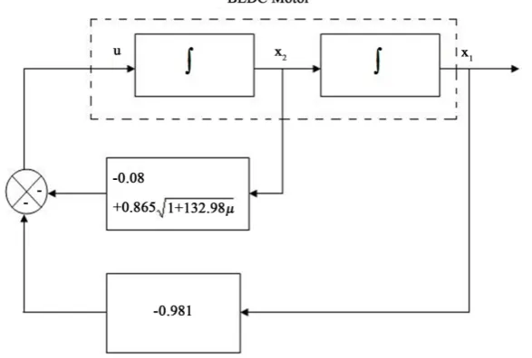
This control signal yields an optimal result for any initial state under the given performance index. Figure 2
shows the block diagram for optimal control of the BLDC drive system.
6. Conclusion
[image:7.595.168.462.505.703.2]To achieve the desired system response, the BLDC drive system had designed with state variable feedback. Also the performance index value is minimum for BLDC drive which was designed by optimal control. In accordance with the expenditure of energy and resources, the control signal is often included in the performance integral. From the foregoing analysis, the value of K2 is obtained as 1.0149 so that the performance index is minimized. The minimum value of performance index is obtained as 1.47. This optimal controlled BLDC drive system re-sults in a minimum value for the performance index. Also, the control law given by Equation (54) yields optimal
results for any initial state under the given performance index. This design based on the quadratic performance index yields a stable control system for the BLDC drive system.
References
[1] Pillay, P. and Krishnan, R. (1989) Modelling, Simulation, and Analysis of Permanent Magnet Drives, Part I. The Per-manent Magnet Synchronous Motor Drive. IEEE Transaction on Industrial Applications, 25, 265-273.
http://dx.doi.org/10.1109/28.25541
[2] Pillay, P. and Krishnan, R. (1989) Modelling, Simulation, and Analysis of Permanent Magnet Drives, Part II. The Permanent Magnet Synchronous Motor Drive, IEEE Transaction on Industrial Applications, 25, 274-279.
http://dx.doi.org/10.1109/28.25542
[3] Krishnan, R. (2009) Electric Motor Drives, Modelling, Analysis and Control. PHI Learning Private Limited, New Delhi. [4] Sathyan, A., Milivojevic, N., Lee, Y.J. and Krishnamoorthy, M. (2009) An FPGA-Based Novel Digital PWM Control
Scheme for BLDC Motor Drives. IEEE Transaction Industrial Electronics, 35, 3040-3049. http://dx.doi.org/10.1109/TIE.2009.2022067
[5] Kuo, C.-F.J. and Hsu, C.-H. (2005) Precise Speed Control of a Permanent Magnet Synchronous Motor. International Journal of Advanced Manufacturing Technology, 28, 942-949.http://dx.doi.org/10.1007/s00170-004-2447-2
[6] Venkitaraman, R. and Ramaswami, B. (1981) Thyristor Converter-Fed Synchronous Motor Drive. Electric Machines and Electro Mechanics, 6, 433-449.
[7] Pan, C.-T. and Fang, E. (2008) A Phase-Locked-Assisted Internal Model Adjustable-Speed Controller for BLDC Mo-tors. IEEE Transaction Industrial Electronics, 55, 3415-3425.http://dx.doi.org/10.1109/TIE.2008.922600
[8] Rodigeuz, F., Desai, P. and Emadi, A. (2004) A Novel Digital Control Technique for Trapezoidal Brushless DC Motor Drives. Proceedings on Electronics and Technology Conference, Chicago, November 2014.
[9] Rodigeuz, F. and Emadi, A. (2005) A Novel Digital Control Technique for Brushless DC Motor Drives: Conduction- Angle Control. Proceedings of IEEE International Conference on Electric Machines and Drives, San Antonio, 15 May 2005, 308-314.
[10] Ogata, K. (1998) Modern Control Engineering. International Edition, Prentice-Hall of India, New Delhi.
[11] Dorf, R.C. (1998) Modern Control Systems. Addison Wesley Longman Inc., Boston.
[12] Murugan, M., Jeyabharath, R. and Sarankumar, V. (2015) An Approach of PFC in BLDC Motor Drives Using BLSEPIC Converter. TELKOMNIKA Indonesian Journal of Electrical Engineering, 14, 215-221.
[13] Niasar, A.H., Moghbeli, H. and Vahedi, A. (2006) Implementation of Four-Switch Brushless DC Motor Drive Based on TMS320LF2407 DSP. IEEE International Conference on Signal Processing and Communications, Dubai 24-27 November 2007, 332-335.
Submit or recommend next manuscript to SCIRP and we will provide best service for you:
Accepting pre-submission inquiries through Email, Facebook, LinkedIn, Twitter, etc. A wide selection of journals (inclusive of 9 subjects, more than 200 journals) Providing 24-hour high-quality service
User-friendly online submission system Fair and swift peer-review system
Efficient typesetting and proofreading procedure
Display of the result of downloads and visits, as well as the number of cited articles Maximum dissemination of your research work