Introduction
Congratulations on your purchase of a DASH2 display unit from Race Technology. This is an advanced, feature-packed display system, designed to be compact, robust and water resistant. Make sure that you follow this instruction manual to ensure correct installation and operation; and the DASH2 should provide you with many years of trouble-free service.
You should begin by installing the provided software onto your PC. The CD contains the latest versions of all the Race Technology standard software products, including the DASH2 configuration program and the Race Technology Online Help System. After installation, the Help System is accessible under the heading “Documentation” “Start\Program Files\Race Technology”. If you encounter any problems with the installation and operation of your DASH2 please refer to the Online Help System in the first instance. If, after this, you are still experiencing difficulties, please visit the support page on the website for further assistance – this can be found at www.race-technology.com/support.
Race Technology Ltd. VAT reg. 715 9671 09
Contents
Introduction ... 2
Contents ... 3
DASH2 General Layout ... 4
What’s in the Box? ... 5
Installing the DASH2 ... 5
Physical installation of the Display Unit ... 5
Electrical installation ... 5
Connection to a data logger ... 8
Switch inputs ... 8
Connections to the vehicle wiring harness... 9
Indicators/hazard warning lights ... 9
Main beam warning light ... 9
Brake warning light ... 9
Fog light warning ... 9
Alternator charge warning ... 9
Sidelight input ... 9
Wheel speed input ... 10
Engine speed input ... 10
Analogue inputs ... 10
Setting up the DASH2 from a PC ... 10
Uploading configuration data to the DASH2 ... 11
Directly from the PC ... 11
Through a data logger ... 11
Operating the DASH2 ... 11
Menu structure ... 12
Logging status display ... 14
Changing displayed information ... 14
Starting and stopping a data logger from the DASH2... 14
Programming soft buttons ... 15
Reviewing maximum and minimum data values ... 15
Resetting a monitored value to zero for change measurement ... 15
Setting up internal/external RPM and vehicle speed readings ... 16
Changing the speed / distance units ... 16
Using an Internal input for Gear calculations ... 17
Odometer and trip meter ... 17
Resetting the trip meter ... 18
Configuring and changing the brightness of the shift lights... 18
Setting warning and sector display times ... 18
Lap timing on the DASH2 ... 18
Adding track markers from the DASH2 or DL1/DL2 ... 19
Adding track markers from the Analysis Software ... 19
Using lap marker files with the DASH2 ... 20
Lap timing operation ... 20
Predictive lap times ... 20
Using target marker and sector times ... 21
Copying current lap/sector times to memory ... 21
Editing target lap/sector times ... 21
Using target marker/sector times ... 21
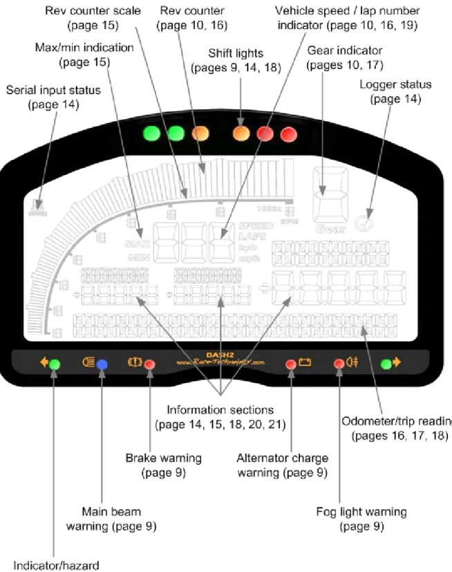
DASH2 General Layout
Race Technology Ltd. VAT reg. 715 9671 09
What’s in the Box?
Please take a few moments to ensure that you have received all of the following components:: The DASH2 display unit itself
Wiring harness with one conn1 connector and one conn2 connector, with a 9 way D-type connector, for connection to a data logger or PC.
Serial extension cable, to enable connection to a PC for configuration Instruction manual
Comprehensive software CD Printed mounting template
Carrying case with cut foam interior
Installing the DASH2
Physical installation of the Display Unit
The DASH2 must be securely mounted onto flat surface or suitable bracket. When deciding on a mounting location it is important to position the viewing angle for the best display contrast. The display can be clearly read over a wide range of incidence angles, but it is most clearly viewed from an angle of approximately 10-20° above the display axis.
A printed template has been provided and should be used to check that there is sufficient space for mounting the unit. There should also be room for drilling the clearance holes for the fixing screws and the 14 way electrical connections. All three mounting holes should be used to prevent the unit from loosening under vibration. In addition, the use of a low strength, thread locking compound is recommended for installations in a high vibration environment. Mounting requires M4 fasteners with a thread engagement depth of 5mm. Avoid over tightening the mounting screws to prevent thread damage.
Electrical installation
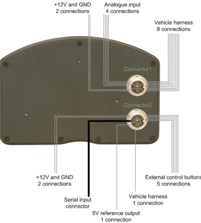
Due to its wide range of features, the DASH2 can be connected in many different configurations. The unit is supplied with a wiring harness consisting of two 14-way connectors to attach to the back of the DASH2, a serial connector for communication with a PC or data logger, and an array of flying leads for connection to the power supply, vehicle harness and external sensors. Figure 2 illustrates all DASH2 connections. Depending on your particular application and the features of the DASH2 that you wish to make use of, it may not be necessary to make all of the connections shown. The connector pin assignments and connector orientations are given in Table 1 and Figure 3, (pages 7 and 8) respectively. The wiring up of the unit should only be entrusted to competent persons familiar with vehicle wiring installations, as incorrect installation may result in both a risk of fire and damage to the DASH2 unit. THE DASH2 WARRANTY DOES NOT COVER DAMAGE CAUSED BY INCORRECT CONNECTION. The flying leads from the DASH2 harness should be connected to the appropriate leads on the vehicle wiring harness using suitable connectors and with reference to the vehicle circuit diagram. Check the output configuration of any external sensors before connecting these to the DASH2 wiring harness to avoid causing damage to the DASH2 or to the sensor.
Figure 2: DASH2 electrical connections
NOTE: The DASH2 wiring harness is supplied in two sections. With reference to Figure 2 ensure that each harness section is connected to the correct connector on the rear of the DASH2. INCORRECT CONNECTION MAY RESULT IN INTERNAL DAMAGE TO THE DASH2.
NOTE: All connections to the DASH2 should be made with the power supply disconnected. The ends of any unused cables on the DASH2 wiring harness should either be insulated with the cables coiled and secured in a safe manner, or trimmed back and removed altogether.
Race Technology Ltd. VAT reg. 715 9671 09
NOTE: As indicated in Figure 2, the DASH2 is provided with its own power input and ground connections. These should normally be connected directly to a 12V power supply, but if the DASH2 is used with a DL2 data logger it is also possible to power the DASH2 from the DL2 by connecting the DASH2 +12V wire to Pin 7 of Conn1, Conn3 or Conn4 on the DL2, and the DASH2 ground wire to Pin 12 of Conn1, Conn3 or Conn4 on the DL2. It is
recommended that a switch is included in the power supply wire to the DASH2; otherwise the unit will be on whenever power is supplied to the DL2, regardless of whether the DL2 is actually turned on or not.
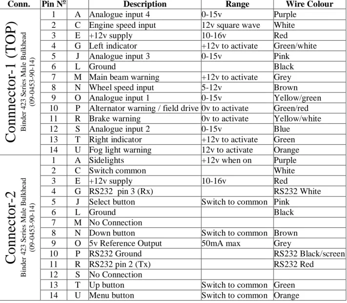
Conn. Pin No Description Range Wire Colour
C
o
n
n
n
e
cto
r-1
(
T
OP)
Bi nde r 4 23 S e ri e s M a le Bu lkh e a d (09 -0453 -90 -14)1 A Analogue input 4 0-15v Purple
2 C Engine speed input 12v square wave White Red
3 E +12v supply 10-16v Red
4 G Left indicator +12v to activate Green/white
5 J Analogue input 3 0-15v Pink
6 L Ground Black
7 M Main beam warning +12v to activate Grey
8 N Wheel speed input 5-12v Brown
9 O Analogue input 1 0-15v Yellow/green
10 P Alternator warning / field drive 0v to activate Green/red
11 R Brake warning 0v to activate Yellow/white
12 S Analogue input 2 0-15v Blue
13 T Right indicator +12v to activate Green 14 U Fog light warning 12v to activate Orange
C
o
n
n
ec
to
r-2
Bi nde r 4 23 S e ri e s M a le Bu lkh e a d (09 -0453 -90 -14)1 A Sidelights +12v when on Purple
2 C Switch common White
3 E +12v supply 10-16v Red
4 G RS232 pin 3 (Rx) RS232 White
5 J Select button Switch to common Pink
6 L Ground Black
7 M No Connection
8 N Down button Switch to common Brown
9 O 5v Reference Output 50mA max Grey
10 P RS232 Ground RS232 Black/screen
11 R RS232 pin 2 (Tx) RS232 Red
12 S No Connection
13 T Up button Switch to common Green
14 U Menu button Switch to common Orange
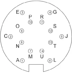
Figure 3: Connector orientation.
NOTE: Please take special care to ensure correct orientation relative to connector keyway when identifying connector pins.
Connection to a data logger
The DASH2 can be connected to the serial output port of a DL1 or DL2 data logger, an AX22 performance meter, or a SPEEDBOX speed sensor. By connecting the unit in this way, many more data channels are available compared to when used in stand-alone configuration. For example, when connected to a DL1 data logger, some of the additional information that is available for real-time display is:
Battery voltage
8 additional analogue inputs 4 frequency inputs
Vehicle position (and position accuracy) Vehicle speed (and speed accuracy) Vehicle altitude (and altitude accuracy) Vehicle heading
Lap and sector timing
The DASH2 is connected to the output from a DL1, DL2, AX22 or SPEEDBOX using the serial connector provided on the Connector2 section of the DASH2 wiring harness, as shown in Figure 2. This connection is optional and does not affect the stand-alone functions of the DASH2. When connected to the vehicle harness and to a data logger, the DASH2 has a choice of which vehicle speed and engine speed inputs to use. See Page 14 for information on how to configure which inputs the DASH2 uses in this situation.
Switch inputs
Four buttons should be connected to the DASH2 to allow in-vehicle control of many functions and display options. These buttons are required to set certain display functions and options, as described on Page 11. Momentary push-to-make buttons should be used. These are available from Race Technology or from any good electrical or automotive component supplier. Each button must be wired with one terminal connected to the switch common and
Race Technology Ltd. VAT reg. 715 9671 09
the other terminal connected to the relevant DASH2 switch input. The switch common pin and four switch input pins are all included in Connector2, as shown in Table 1 and Figure 2.
Connections to the vehicle wiring harness
Indicators/hazard warning lights
The warning lights for the indicators and hazard lights are activated by applying 12v to Connector1, pins 4 and 13 (left and right indicators, respectively) as ident ified in Table 1. These should normally be connected directly to the vehicle wiring loom between the indicator switch and the indicator itself.
The brightness of the LEDs will vary depending on the status of the sidelight input. This feature is included to dim the indicator warning lights at night to avoid dazzling the driver, yet allow them to be clearly visible during daylight hours.
Main beam warning light
The main beam warning light is activated when 12v is applied to Connector1, Pin 7, as shown in Table 1. This is usually achieved by connecting to the vehicle wiring loom between the headlight switch and the main beam bulb(s).
Brake warning light
The brake warning light is activated when 0v is applied to Connector1, Pin 11, as shown in Table 1. This is usually achieved by connecting directly to the handbrake warning switch and/or low brake fluid warning switch at the appropriate point in the vehicle wiring harness.
Fog light warning
The fog light warning is activated when 12v is applied to Connector1, Pin 14, as shown in Table 1. This is usually achieved by connecting to the vehicle wiring loom between the fog light switch and the fog light itself.
Alternator charge warning
This warning lamp is illuminated when alternator output is low and the vehicle battery is not being charged. This will be the case when the ignition is turned on but the engine is not running, or if there is an alternator fault. To make use of this feature, Connector 1, Pin 10 should normally be connected to the field/alternator warning terminal on the alternator, via the relevant cable in the vehicle wiring harness.
Sidelight input
The sidelight input is used to alter the brightness of the shift lights and indicator/hazard warning lights. This requires Connector2, Pin 1, as shown in Table 1, to be connected directly into the vehicle wiring loom between the sidelight switch and the sidelights themselves. When the input to this pin is at 0v the shift and indicator/hazard warning lights will be bright, but when the input to this pin is at 12v the shift and indicator/hazard warning lights will be dimmed slightly. The brightness of the shift lights can also be adjusted independently, as described on Page 17.
Wheel speed input
Wheel speed input data are used by the DASH2 for the vehicle speed, odometer and trip recorder displays, and for gear indicator calculations. This input requires a 5v or 12v square wave signal applied to Connector1, Pin 8, as listed in Table 1. This output format is normally provided by a standard vehicle wheel speed sensor. If not already fitted, these are available from Race Technology or from any good electrical or automotive component supplier. There is no conditioning on this input for a VRS sensor. The input has an internal pull down to ground so the input can be activated by a simple switch to either 5 or 12v. The procedure for configuring this input to the correct pulse rate per distance travelled is described on Page 17.
Engine speed input
The engine speed input can be used with the DASH2 in stand alone mode or with a data logger connected, to give an engine RPM input reading. This information is also used in the gear indicator calculation.
This channel requires a 5v or 12v square wave input applied to Connector1, Pin 2, as show in Table 1. IT MUST NOT BE CONNECTED DIRECTLY TO THE IGNITION COIL OR AN INDUCTIVE PICKUP FROM THE HIGH TENSION SIDE OF THE IGNITION SYSTEM. This channel should normally be connected to the engine speed output channel from the engine management ECU.
Analogue inputs
The DASH2 is provided with four, fully configured, analogue input channels of its own. These are in addition to any analogue inputs provided by connection to a data logger. These channels may typically be used to monitor variables such as fuel level, water temperature and oil pressure, via existing sensors. If these are not already provided, suitable items are available from Race Technology. The sensor outputs should be connected to the DASH2 analogue input channels on Connector1, Pins 1, 5, 9 and 12, as listed in Table 1. THE MAXIMUM INPUT VOLTAGE APPLIED TO THESE CHANNELS MUST NOT EXCEED 15V! The input voltages will need scaling to display the correct readings for the physical parameters being measured. This calibration is carried out using the DASH2 configuration software. Further details are included in the Race Technology Online Help System.
Setting up the DASH2 from a PC
The DASH2 display consists of three main sections, each of which has multiple configuration options. These settings can all be changed using the configuration utility program on the supplied software CD. Five user-configurable screens are available, each displaying three sensor input channels, enabling up to fifteen variables to be viewed in total. All data channels can also be simultaneously monitored for alarm conditions. As well as selecting which data is viewed and setting the alarm limits, the configuration software is also used to set the scaling on each input channel, and to set up the RPM display options and gear indicator calculations. The DASH2 is supplied with a default configuration suitable for many typical applications, particularly if external analogue sensors are not in use. This will allow display of all the basic features after connection to the vehicle wiring harness as described above.
Race Technology Ltd. VAT reg. 715 9671 09
To make custom configuration changes, full operating instructions for the configuration software are available from the Race Technology Online Help System, which is also included on the CD provided with the DASH2. Simply follow the path: Software\Configuration and reflash\Configuring display products.
Uploading configuration data to the DASH2
Once changes have been made with the configuration program, the new settings require uploading to the DASH2. This can be done either by a direct serial connection between the PC and the DASH2 or through connection to a DL1, DL2 or AX22 data logger.
Directly from the PC
This requires connection of the DASH2 serial connector and the serial port on the PC, using the serial extension cable provided. A USB to serial adaptor will also be required if the PC does not have a serial port. Full instructions for uploading the new configuration to the DASH2 are provided in the Race Technology Online Help System by following the path: Software\Configuration and reflash\Configuring display products.
Through a data logger
After completing all changes in the configuration software, click on the save button. The file with the new configuration settings must be saved as DASH.DAT on to a compact flash memory card in to the root directory. The compact flash card should then be inserted into the data logger, with the DASH2 connected. The compact flash card may be inserted in to the data logger with the unit and DASH2 powered up. When uploading configuration changes, it is recommended that the new DASH.DAT is the only file on the compact flash card. The DASH.DAT file will be automatically read by the data logger and the new configuration settings will be uploaded to the DASH2. During configuration upload, the display will freeze for a few seconds, before displaying the new settings when the configuration upload is complete. To ensure all new configuration settings are displayed it is recommended to cycle the power supply to the DASH2. The DASH2 stores all configuration settings, so there is no need to repeat this procedure each time the unit is powered-up, unless making changes to the existing configuration.
Operating the DASH2
During normal operation, the DASH2 will display the selected information to the driver and monitor all inputs for alarm conditions. In-vehicle control of the DASH2 functions is via a logical menu structure and four buttons: MENU, SELECT, UP, and DOWN. These allow the user to alter displayed units, switch between data screens, change button functions, and set or configure many other options. When in menu system display mode the actual function of the MENU/SELECT/UP/DOWN buttons is fixed, but their function during normal display mode can be programmed, for example, to provide shortcuts to frequently used features. The MENU button is used to switch between normal display and menu system display. This is the only button whose function cannot be changed.
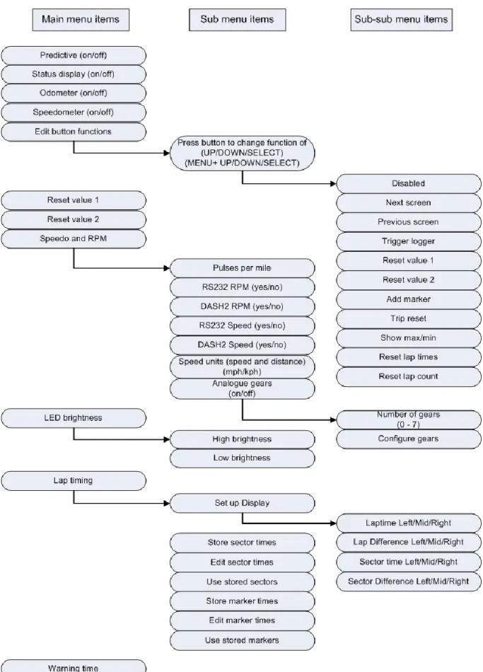
Figure 4 illustrates the structure of the menu system. The following sections describe the details and operation of each function.
Menu structure
Press MENU to enter menu system display mode. Using the UP/DOWN buttons you can then scroll through the following options:
Predictive lap timing on/off Logging status display on/off
Odometer and trip meter display on/off Speedometer on/off
Edit button functions Reset value 1
Reset value 2
Speedo, RPM and gear LED Brightness Lap times Warning times
Race Technology Ltd. VAT reg. 715 9671 09
To edit function settings, display the function in question using the UP/DOWN buttons and press SELECT. Use UP/DOWN to change the function settings, then SELECT to save the new setting and return the DASH2 to its normal display mode. Several menu items also have sub-menus, as shown in Figure 4. In the case of the lap timing functions, first press SELECT to access the lap timing functions from the top level menu, then use the UP/DOWN buttons to display the required sub-menu item and press SELECT again to open the settings, followed by UP/DOWN to change the settings and SELECT to save the new settings and return to normal display mode. In the case of speedo and RPM settings, and LED brightness, press SELECT to access these items from the main menu, then use the UP/DOWN buttons to configure the setting for each item and the SELECT button to save each setting and move onto the next item on that sub-menu. When the last item on the sub-menu is reached pressing SELECT will return the DASH2 to the normal display mode. The normal display mode may also be reached, at any time, by pressing MENU.
Logging status display
The status of an attached logger can be displayed on the DASH2, with a tick mark in the top right hand corner, as shown in Figure 1. It is also possible to set the left hand shift light as a secondary, more highly visible logger status indicator. This is selected using the “Status display” option – item 2 in the DASH2 menu system (see Figure 4). When this mode is enabled, the left-most shift light operates as a logging status indicator. The remaining five shift lights operate as normal. In the top left corner of the display (see Figure 1), the DASH2 also has a binary symbol to indicate that serial communications are being received when the unit is used with a Race Technology data logger or other device, such as a PC.
Changing displayed information
There are five user-configurable screens of data that can be displayed on the DASH2. The data to display on each screen is selected using the DASH2 configuration program on the PC. Once the screens are configured, the programmable buttons can be used to select which screen to display. This enables toggling through the five screens of data. To set up a button to do this, see the section “Programming soft buttons” and assign the “Next screen” or “Previous screen” functions, as shown in Figure 4. When changing between screens, the screen number is briefly indicated at the bottom of the display.
Starting and stopping a data logger from the DASH2
When suitably connected and configured, the DASH2 can be used to start and stop data recording on an attached logger. To enable this feature, set up one of the buttons on the DASH2 to the “Trigger logger” function, as described in the “Programming soft buttons” section. The data logger must be configured to decode serial data to make use of this feature. This can be done in the data logger configuration software. Without setting the data logger up to decode serial data the commands from the DASH2 will be ignored. Whenever the “Trigger logger” button is pressed, a command will be sent to the data logger to start or stop logging. The logger must be powered up and have a correctly formatted card inserted in order to commence logging.
Race Technology Ltd. VAT reg. 715 9671 09
Programming soft buttons
The UP, DOWN, and SELECT buttons can be programmed to perform many different „shortcut‟ functions in normal display mode, these buttons can also be combined with the MENU button to provide a further three soft buttons if required. This does not change the function of the buttons from their standard purpose in menu display mode. To change a button function, simply select “Edit button functions” using the UP/DOWN buttons (main menu, item 3), then press SELECT. You will then be asked to press the button you wish to change the function of. Press either SELECT, UP, or DOWN to access the three extra soft buttons, press and hold MENU, without releasing it, press SELECT, UP, or DOWN. The display will change to show which button is selected and the current function assigned to that button. The UP and DOWN buttons can then be used to select any one of 12 functions to assign to this button, as shown in the sub-sub menu in Figure 4. Press SELECT to confirm the button function and return to the main menu.
Reviewing maximum and minimum data values
The DASH2 can store and display maximum and minimum values for each of its input channels. These values can be reviewed by setting one of the buttons to the “Show max/min” function as shown in the sub-sub menu in Figure 4. Refer to “Programming soft buttons” and set the button function to “Show max/min”. Whenever this button is pressed it will temporarily replace the current three displayed channels with their maximum values. This display will be held for around five seconds, during this time, moving on to another display screen will reset the timer, thus enabling you to scroll through all display screens and view all maximum values. If the max/min button is pressed again during this time the screen will change to show the minimum values. A third press of the button will reset all Max/Min values.
Resetting a monitored value to zero for change measurement
Whilst most values displayed on the DASH2 will show an absolute reading, such as the water temperature or quantity of fuel in the tank, there are times when it would be useful to monitor changes in value, such as how much fuel has been used to cover a certain distance. To achieve this, the DASH2 can be configured to reset a channel to zero on a single button press. There are two steps in this process: Firstly selecting which channel to reset and then secondly setting one of the buttons to perform the reset function.
To select which channel to reset, go to “Reset value 1”, or “Reset value 2”. Press SELECT then use the UP/DOWN buttons to scroll through the list of available channels until you see the one you wish to reset. Press SELECT to choose this channel and return to normal display mode.
To set up a button to perform the reset function see “Programming soft buttons” and set the button to either “Reset value 1” or “Reset value 2”. Whenever this button is pressed it will reset the displayed value of the selected channel to zero. To return the channel to reading its normal value, change to another channel on the reset button, and/or change the button function.
Setting up internal/external RPM and vehicle speed readings
The DASH2 can display RPM and vehicle speed data from two different sources: Either from vehicle sensors wired directly to the DASH2 inputs (termed “internal” or DASH2 inputs), or via the output from an external data logger (termed “RS232” inputs). If the DASH2 is always used with a data logger, it is better to configure the unit to use the RPM output from the data logger so that a high level RPM input can be used. The vehicle speed output from the data logger would also give a more accurate input to the DASH2, but would only be present when the GPS signal is valid. The odometer and trip counter only use the pulse input from the “internal” vehicle sensor, so if the DASH2 is set up to use only the external speed input the odometer will not function. When RS232 speeds are enabled, the odometer updates in the same way as for the internal speed input, when used this way, the unit must be set up for a minimum of 400 pulses per mile. Otherwise the odometer readings will become inaccurate. For road legal applications the DASH2 must be used with a wheel speed input to measure vehicle speed and enable operation of the odometer and trip meter.
Configuring the DASH2 to read both input sources for RPM or vehicle speed simultaneously should be avoided. This can lead to information on the screen becoming unstable due to conflicting data being read from the two sources. The RPM and vehicle speed sources are selected from main menu item 6; “Speedo and RPM”, followed by selecting yes/no for “RS232 RPM” / “DASH2 RPM” and “RS232 speed” / “DASH2 speed”, where RS232 input refers to “external” data from a logger and “DASH2” input refers to “internal” sources from vehicle sensors connected directly to the DASH2.
Recommendations:
1. Without a data logger connected: Use vehicle sensors to provide “internal” inputs to DASH2. RS232 inputs may be left enabled; with no signal present on these channels they will cause no disruption to normal operation
2. Road car with data logger: Internal wheel speed input, otherwise there will be no odometer. Internal RPM if available, otherwise external through data logger
3. Race car with data logger: External speed and RPM from data logger
To set the correct scaling and configuration of the RPM input, please refer to the DASH2 configuration software.
Changing the speed / distance units
Speed and distance are displayed in mph/miles by default. To change this to kph/km select “Speedo RPM Gear” from the main menu, then press the SELECT button until “Speed units” is displayed. Use the UP/DOWN buttons select the desired display units, then press SELECT to save the new setting and return to normal display mode.
NOTE: Although it is possible to select km or miles for the odometer and trip displays, the calibration for the wheel speed input is always in pulses per mile. If calibration data for external sensors is quoted in pulses per km this must be converted to pulses per mile to be entered as a calibration factor for the DASH2 in the configuration software.
Race Technology Ltd. VAT reg. 715 9671 09
Using an Internal input for Gear calculations
As well as calculating which gear is currently in use from the ratio of the RPM and wheel speed inputs, the DASH2 can use analogue channel 1 as in input to show which gear is selected. To set the DASH2 up for gear indication, set the Ana Gears option to “On”, next you will be asked how many gears are present. Here, enter the number of forward gears. The unit will automatically add on for reverse and neutral. After setting the number of gears, the display will change to show the current gear being edited, “STORE” which is the stored reading for the current gear, and “NEW” which is the current reading on the analogue input. To set up a particular gear, use the UP and DOWN buttons to select the required gear and then press the SELECT button to store the reading. The value from the NEW window will now appear in the STORE window, showing that the upgrade has been completed. When you have finished setting up the gears, press the MENU button to exit and store the readings. Please note that the DASH2 rounds off to the nearest Volt. For example, if gear 1 is set to 3v and gear 2 is set to 4v and voltage reading between 2.51 and 3.50 will be gear 1.Similarly, any reading between 3.51v and 4.50v will be gear 2.
Odometer and trip meter
The DASH2 features a non-resettable odometer as well as a resettable trip counter. These counters are both driven from the “internal” wheel speed input (i.e.: from vehicle sensors connected directly to the DASH2). As such, if the wheel speed input is not used (as might be the case if the DASH2 is connected only to a data logger for vehicle speed data) the odometer will not function.
For the odometer to function correctly, the number of pulses per mile must be set. Change this using “Speedo and RPM”, followed by “Pulses per mile” from the sub-menu. Use the UP/DOWN buttons to toggle to the desire value, then press SELECT to save the new setting. To calculate the number of pulses per mile, measure on the ground the distance travelled during one complete wheel rotation in metres or inches and use one of the following formulae:
Distance in meters: Pulses per mile = 1609/rolling circumference of wheel
Distance in inches: Pulses per mile = 63360/rolling circumference of wheel
NOTE: These formulae assume 1 output pulse per wheel rotation. The DASH2 configuration software also allows for calibration with wheel speed sensors giving more than one pulse per revolution, as described in the Race Technology Online Help System. To calculate the number of pulses per mile in the case, simply multiply the result of the equations overleaf by the number of pulses per wheel rotation.
It is also possible to hide both the odometer and trip meter – for example in racing applications when this information is not relevant. To hide the odometer and trip meter select “Odometer” from the DASH2 menu system, as shown in Figure 4, and use the SELECT/UP/DOWN buttons to change the setting.
Resetting the trip meter
To reset the trip meter, one of the programmable buttons (UP, DOWN, or SELECT) must be configured to perform the reset function. To set up a button to do this, see the section “Programming soft buttons” and assign a button to the “Trip reset” function. When this button is pressed in normal display mode the bottom section of the display will then read “trip reset”. Press any button to return to normal display mode with the trip meter reading zero.
Configuring and changing the brightness of the shift lights
Configuration of the shift lights is carried out in the DASH2 configuration software, under the “RPM setup” tab. The engine speeds at which the LEDs illuminate are set by first entering a value for “RPM of final shift light”. This is the engine speed at which all 6 LEDs will flash and would typically be set to the maximum permissible engine speed. The engine speed interval between illumination of each shift light (1,2,3,4,5,6,6+flashing) is then defined by entering the engine speed interval in the “Shift light interval” field. The brightness of the shift lights is controlled from the DASH2 itself. The sidelight input to the DASH2 is used to detect when the vehicle lights are turned on and dim the shift lights and indicator lights accordingly. The brightness of the shift lights at both high and low settings can be altered by the user to suit personal preference. To do this, go to “LED brightness” and press SELECT. The shift lights will then be illuminated at the current high brightness setting. The UP and DOWN buttons can be used to edit the brightness to the desired level. Then press SELECT to save the high brightness setting and move on to the low brightness setting. Again, use the UP and DOWN buttons to set the desired brightness, then press SELECT to save and return to normal display mode. If the sidelight input is not connected the shift LEDs will remain at the high brightness setting at all times.
Setting warning and sector display times
The duration for which warning messages and sector times are displayed on the screen can also be configured from the DASH2 menu system. Enter menu display mode and use the UP/DOWN buttons to display “Warning times”, in the main menu and press SELECT. Then use the UP/DOWN buttons to select the desired warning duration, press SELECT to save the new setting, then use the UP/DOWN buttons to set the duration of the sector time display and press SELECT again to save this setting and return to normal display mode. The red shift lights on the right will flash when the warnings are displayed.
Lap timing on the DASH2
To use the DASH2 lap timing functions the unit must be connected to a Race Technology DL1 or DL2 data logger. The data logger monitors when the vehicle has passed a track marker and sends the lap or sector timing information to the DASH2 which displays the data and stores best lap and sector times. The lap timing functions only operate when the data logger is logging data. If the logger is just monitoring sensors and sending this information to the DASH2 no lap or sector times will be displayed. The lap timing functions use GPS data from the data logger, so can only function correctly when the logger has a valid GPS lock. Lap timing functions use GPS coordinates as track markers to define sectors and laps. These markers can be added either by setting up a button on the DASH2 to add a marker, by using a dedicated button connected to the data logger, or by adding them to data using the Race
Race Technology Ltd. VAT reg. 715 9671 09
Technology Analysis Software and saving the resulting .lap file to the memory card for transfer to the data logger. Each of these options is explained in detail below.
Adding track markers from the DASH2 or DL1/DL2
To use a DASH2 button to add markers, refer to “Programming soft buttons” and programme one of the buttons to perform the “Add marker” function, as illustrated in Figure 4. To use a DL1/DL2 switch, connect a switch to the data logger as described in the documentation provided with the data logger itself.
When the data logger is in operation, a track marker will be added each time the DASH2 or logger button is pressed. When you wish to add track markers, it is advisable to drive slowly around the circuit and press the “add marker” button each time you pass a point you wish to use as a track marker. The first marker you add will ALWAYS be the LAP marker. The markers you subsequently add will split the track up into sectors. It should also be noted that each marker has an approach direction associated with it, as well as a position. This means that if you have a hairpin with the two straight-ways fairly close together and you added the track marker as you approach the hairpin, then both the approach and exit paths will cross the track marker, but the only time the software will log that you've crossed the track marker is when you have passed the marker in the same direction as it was added.
If the addition of a desired track marker was missed, it is possible to add a marker in after the first lap. The data logger will calculate where the track marker is in comparison to the track you have drawn so far, and if it is in between two other markers, the hardware will split the sector into two, but the track marker will be numbered as the next value.
When you press the button to add a track marker, a marker will be added at the next GPS sample point, so it could be up to 0.2 seconds before the marker is actually added (depending on the model and specification of data logger used). If you are travelling slowly when the markers are added this will have no serious side effects. If you are travelling quickly, it is unlikely that you will be able to position the track markers with great accuracy. This will not affect the timing between markers, as these are in the same place on every lap, but may affect the positioning of the markers with respect to circuit features.
Adding track markers from the Analysis Software
Track marker files can also be written to the Compact Flash card. The file names MUST be in 8.3 format, meaning that the entire file name must be in UPPERCASE letters, and it must have no more than 8 characters before the decimal point. The file extension MUST be .LAP, and must also be in UPPERCASE letters. If the files are not named in this way the data logger will not recognise them.
To generate a .LAP file from raw data, please refer to the section on “Adding Track Markers” in the Analysis Software documentation or Race Technology On-line Help System. The resulting .LAP file should be saved to compact flash card for transfer to the data logger. The .LAP file must be placed in the root directory of the Compact Flash card. It is advisable not to have multiple .LAP files with similar marker locations in this directory to avoid the possibility of the data logger selecting the wrong lap marker file if multiple .LAP files are present.
Using lap marker files with the DASH2
The data logger stores the lap markers in a .LAP file in the root directory of the compact flash card. At the start of a run, the data logger will check its current position against the reference positions in any .LAP files on the memory card. As such, you can have 10 different .LAP files on the card, and so long as they were not started within about 15km of each other, the data logger will pick up the correct one for the current location. For this reason, it is very important that the data logger has a GPS lock at the start of the run; otherwise it will just pick up the first file found. If there are no files on the compact flash card, then it will write to the file MARKER01.LAP, if MARKER01.LAP already exists, it will go to MARKER02.LAP, and so on.
Lap timing operation
With a .LAP marker file present on the compact flash card, lap timing operation will start automatically when you pass the start/finish marker for the first time with the data logger on, with GPS lock and logging data. After this, when you complete each sector, the time will be compared with the time to that point on your fastest lap, and your fastest time for that particular sector. These times will be displayed on the DASH2 in the following format:
SECT LAP LAP
+0:00.21 +0:30.62 +0:00.19
The first value is the sector time information, showing that at this marker the time was 0.21s slower than the best time for that sector. The second value is the time to this point on the lap, showing that it has taken 30.62s. The third value is the difference between current and the best time to this point on the lap. The driver is 0.19s slower than on the best lap, in this case. The sector timing will continue in this way for each sector marker passed until the end of the lap, at which time the lap time and sector times will be compared against the previous best ones, the best will be updated as required (unless stored lap or marker times are being used). The vehicle speed display will temporarily be replaced with the number of laps completed each time a lap marker is passed. The lap counter will be reset every time that data logging is stopped or started on the data logger.
Predictive lap times
With predictive lap timing enabled, instead of the lap times being shown as the time up to that point in the lap, the lap time is extrapolated to estimate the lap time if the rest of the lap was covered at the same pace as the fastest lap. For example, if the best lap time was previously 2:45.23, after passing the first sector marker the DASH2 will display:
SECT LAP LAP
+0:00.21 +2:45.42 +0:00.19
The first value is again the difference between the time for the sector just completed and the best time for that sector. The second value is the predicted lap time if the remainder of the lap is covered at the same pace as the fastest lap and the third value is the resulting difference between the predicted current lap time and the fastest lap time. Then, after passing the second
Race Technology Ltd. VAT reg. 715 9671 09
sector marker the following screen could be displayed. The first figure indicates that the second sector was covered 1.00s faster than the previous fastest time for that sector. The second figure is the update predicted lap time and the third figure is the difference between this predicted lap time and the current fastest lap time.
SECT LAP LAP
-0:01.00 +2:44.42 -0:00.81
Using target marker and sector times
The best lap and sector times will be reset by default each time you start a new run. There is a mode on the DASH2 where the lap and sector times can be edited and kept from one run to the next. This is very useful for pacing functions where a comparison against a known lap time is required.
The lap timing is split into two sections, sector times and lap times. The lap times are the times from the beginning of the lap to the given marker, whereas the sector times are the total times for the given sector. The two sets of timing data are set up independently. Thus it is possible to monitor performance against fixed sector times whilst still having a constantly updated best lap time or vice versa.
Copying current lap/sector times to memory
After completing a run, the lap and sector times from the run can be stored to use as a reference for the next run. To do this, go to “Lap timing”, followed by “Store sector times”, to store sector times or “Store marker times”, to store lap times. In each case press the SELECT button to save the current sector or lap times to the DASH2 memory. Once the times have been stored to memory they can be used for subsequent runs or edited.
Editing target lap/sector times
To edit the target sector or lap times, go to “Lap timing”, followed by “Edit sector times” or “Edit marker times”, and press SELECT to edit the stored target sector and lap times, respectively. NOTE: Target sector and lap times must first be stored to the DASH2 memory before they are available for editing. The screen will now show the marker or sector times for each sector. Use the UP and DOWN buttons to select the sector time to edit, and then press the SELECT button. The UP and DOWN buttons can now be used to change the target time. Pressing and holding the buttons will cause the times to change faster. When the required time is displayed press the SELECT button to save the new time and return to the previous screen, to enable selection of another sector for editing. When all times are set, press the MENU button to exit and return to display mode.
Using target marker/sector times
To use the target sector times and lap times, go to “Lap timing”, followed by “Use stored sectors” or “Use stored markers”. Press SELECT, then use the UP and DOWN button to set the option to “yes” and SELECT to save and exit. For each run, lap and sector times will then be compared with the target values stored in the DASH2 memory.
Re-flashing the DASH2
The DASH2 firmware can be re-flashed to take advantage of any software changes or new features introduced. To find out which firmware is on the DASH2 press and hold the “down” button before turning on the power to the DASH2, the firmware version will be displayed on the screen. New firmware upgrades will be introduced from time to time as new features are implemented. Firmware files will be available for download and installation from the Race Technology website. Re-flashing can be done either through a connection to a Race Technology data logger or through serial connection to a PC. Full details of how to perform the re-flashing process are provided with all firmware updates, or from the Race Technology Online Help System. PLEASE DO NOT ATTEMPT TO REFLASH YOUR DASH2 UNLESS YOU ARE ABSOLUTELY CONFIDENT IN THE REQUIRED PROCEDURE AND HAVE READ THE REFLASHING INSTRUCTIONS IN FULL.