Equipment Issue 1 Second Printing, August 1999 Charles Industries, Ltd.
1999 Charles Industries Ltd.
CLEI is a trademark of Bell Communications Research, Inc.
STS 3192–9P Short Loop Office Repeater
Complies with UL Standard 1459 Second Edition.
CONTENTS PAGE
Part 1. GENERAL . . . 2
Part 2. TESTING . . . 4
Part 3. TECHNICAL ASSISTANCE . . . 5
Part 4. WARRANTY & CUSTOMER SERVICE . . . 5
Part 5. SPECIFICATIONS . . . 6
Wescom
SHORT LOOP RPTR
3192–9P
D S X R P T M O N
R C V
X M T D S X R P T M O N 91-31929P
0.6V
ISS 1
FA
2
1.
GENERAL
1.1 Document Purpose
This document provides general and testing information for the Charles Industries 3192–9P Short Loop Office Repeater, shown in Figure 1.
1.2 Document Status
This document is reprinted to provide a general editorial update.
1.3 Equipment Function
The 3192–9P is an optionless repeater intended for applications where T1 service is provided to a customer premise via a lightwave multiplexer and short non-repeated metallic extensions are provided beyond the normal DSX range. In this application, a STS shelf equipped with 3192–9P units is co-located with the fiber multiplexer providing up to 3000 foot repeaterless metallic extensions. The 3192–9P contains a –48 volt current regulator that provides simplex current at a constant 60mA to power a DS1 Connector located at the Network Interface. The 3192–9P cannot be used in T1 service applications where the Local Exchange Carrier provides network power to operate the customer’s T1 CSU.
1.4 Equipment Features
Provides a wide range ALBO (Automatic Line Build-Out) that will regenerate incoming signals that have experienced from 0 to 35dB of loss. No optionable padding of the incoming signal is required.
Transformer-coupled passive transmit path with a fixed insertion loss of approximately 1.0dB.
Provides a fault locate output. A resistive network on the secondary of the fault locate transformer provides the proper termination to the repeater when fault locate filters are not being deployed; eliminating the need to short the fault locate output when not in use.
When the 3192–9P’s internally-located fuse opens, the front-panel-mounted FA LED will illuminate and –48 volts will appear at the Fuse Alarm output (pin 10). The fuse will only open if the module is damaged and the fuse is not field replaceable.
Front-panel-mounted bantam jacks that provide split and monitor access to the DSX.
Front-panel-mounted pin jacks for measuring span current and voltage.
Provides a fixed pre-equalization for up to 110 feet of 22 gauge cable or 90 feet of 24 gauge cable.
Units are shipped in static-protective material to protect static-sensitive devices. Use static-preventive measures for storage and handling.
STATIC-SENSITIVE
Potentially hazardous voltages can exist on carrier span lines. Always exercise caution when wiring a live circuit or when performing maintenance on the backplane of any span shelf.
Table 1. 3192–9P Front Panel Function Description
ITEM FUNCTION
FA (Fuse alarm) Red LED Indicates that the internal fuse on the 3192-9P has opened. The internal fuse is not field replaceable.
RCV Bantam Jacks DSX Isolates repeater allowing injection of signal toward the DSX. RPT Isolates the DSX allowing monitoring of repeater RCV DSX (OUT). MON Non-service-affecting RCV DSX (OUT) monitor jack.
Voltage and Current Test Pins Used for measuring span current and voltage (see Testing). XMT Bantam Jacks DSX Isolates the repeater allowing monitoring of signal from the DSX.
RPT Isolates the DSX allowing injection of signal toward the span. MON Non-service-affecting XMT DSX (IN) monitor jack.
3192–9P REPEATER
N.I. CABLE LOSS 15dB MAXIMUM
TOTAL LOSS 16.5dB
250 ohm Maximum
CSU LOCAL POWER
Local Power DS1
CONNECTOR LOOP POWERED LIGHTWAVE
MULTIPLEXER
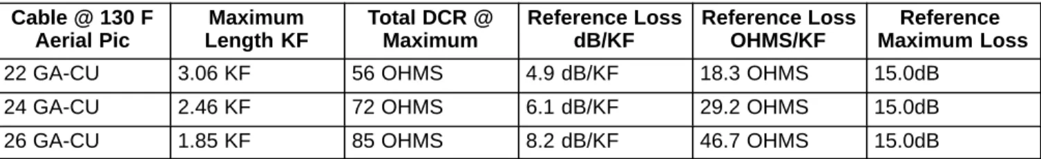
Note: Range is limited to maximum cable loss of 15.0db. See the table below for maximum cable length at various cable gauges.
Cable @ 130 F Aerial Pic
Maximum Length KF
Total DCR @ Maximum
Reference Loss dB/KF
Reference Loss OHMS/KF
Reference Maximum Loss
22 GA-CU 3.06 KF 56 OHMS 4.9 dB/KF 18.3 OHMS 15.0dB 24 GA-CU 2.46 KF 72 OHMS 6.1 dB/KF 29.2 OHMS 15.0dB 26 GA-CU 1.85 KF 85 OHMS 8.2 dB/KF 46.7 OHMS 15.0dB
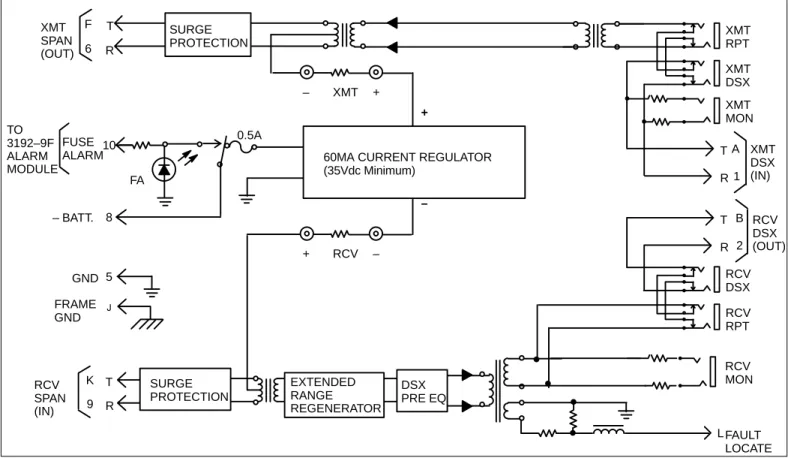
4 F XMT SPAN (OUT) 6 5 K 9 10 8 0.5A SURGE PROTECTION XMT DSX (IN) FA FUSE ALARM – BATT. SURGE PROTECTION RCV SPAN (IN) GND J FRAME GND RCV DSX (OUT) B A 1 2 XMT DSX XMT MON XMT RPT RCV DSX RCV RPT EXTENDED RANGE REGENERATOR L FAULT LOCATE + – T R T R T R T R – + RCV MON TO 3192–9F ALARM MODULE XMT – + RCV
60MA CURRENT REGULATOR (35Vdc Minimum)
DSX PRE EQ
Figure 2. 3192–9P (Issue 1) Office Repeater Block Diagram
2.
TESTING
If trouble is suspected with the 3192–9P Short Loop Office Repeater, use the following procedure to test the unit. This test is to be performed in service, with the 3192–9P under test and continuing to receive T1 signals from the metallic facility as well as the DSX. Also, the test can be performed out-of-service, in an appropriate test setup that would provide an equivalent T1 signal source.
Step Action Verification
1. With a voltmeter, check for DC voltage between terminals 1 (–48V) & 3 (Gnd) and 2 (–48V) & 4 (Gnd) on terminal block TB–1. Verify span current and voltage at front panel test points.
Local battery voltage across terminals 1 & 3 and 2 & 3 of TB–1 should be between –42V and –56V. Verify span current; the DC voltage between the front panel test points should read 0.6 + 0.03 Vdc. This corresponds to a span line current of 60mA + 5 percent. Span voltage can be verified by connecting the neg-ative lead of the voltmeter to the upper right (front panel) test point and the positive test lead to the lower left (front panel) test point.
2. Check for the existence of the regen-erated receive signal.
When checking with a T1 transmission test set, pulses should be observed. If not, replace the 3192–9P (see note).
3. Check for signal error (bipolar viola-tions) in the regenerated receive sig-nal.
The error indicator on the T1 transmission test set should not light. If excessive errors are evident, replace the unit (see note).
4. Verify the transmit signal on the span line.
A valid signal received from the DSX should be observed on the T1 transmission test set. Verify the wiring from the DSX. (This test assumes that the XMT from DSX signal input is a 3V (base to peak) 1.544mb/s T1 signal.)
3.
TECHNICAL ASSISTANCE
3.1 Technical Assistance — U.S.
If technical assistance is required, contact Charles Industries’ Technical Services Center at: 847–806–8500
847–806–8556 (FAX) 800–607–8500
[email protected] (e-mail)
3.2 Technical Assistance — Canada
Canadian customers contact:
905–821–7673 (Main Office) 905–821–3280 (FAX)
4.
WARRANTY & CUSTOMER SERVICE
4.1 Warranty
Charles Industries, Ltd. offers an industry-leading, 5-year warranty on products manufactured by Charles Indus-tries. Contact your local Sales Representative at the address or telephone numbers below for warranty details. The warranty provisions are subject to change without notice. The terms and conditions applicable to any specific sale of product shall be defined in the resulting sales contract.
Charles Industries, Ltd. 5600 Apollo Drive
Rolling Meadows, Illinois 60008–4049
Telephone: 847–806–6300 (Main Office) 847–806–6231 (FAX)
4.2 Field Repairs (In-Warranty Units)
Field repairs involving the replacement of components within a unit are not recommended and may void the war-ranty and compatibility with any applicable regulatory or agency requirements. If a unit needs repair, contact Charles Industries, Ltd. for replacement or repair instructions, or follow the Repair Service Procedure below.
4.3 Advanced Replacement Service (In-Warranty Units)
Charles Industries, Ltd. offers an “advanced replacement” service if a replacement unit is required as soon as possible. With this service, the unit will be shipped in the fastest manner consistent with the urgency of the situa-tion. In most cases, there are no charges for in-warranty repairs, except for the transportation charges of the unit and for a testing and handling charge for units returned with no trouble found. Upon receipt of the advanced re-placement unit, return the out-of-service unit in the carton in which the rere-placement was shipped, using the pre-addressed shipping label provided. Call your customer service representative at the telephone number above for more details.
4.4 Standard Repair and Replacement Service (Both In-Warranty and Out-Of-Warranty Units)
Charles Industries, Ltd. offers a standard repair or exchange service for units either in- or out-of-warranty. With this service, units may be shipped to Charles Industries for either repair and quality testing or exchanged for a replacement unit, as determined by Charles Industries. Follow the Repair Service Procedure below to return units and to secure a repair or replacement. A handling charge applies for equipment returned with no trouble found. To obtain more details of this service and a schedule of prices, contact the CI Service Center at 217–932–5288 (FAX 217–932–2943).
Repair Service Procedure
6
2. Include the following information: – Company name and address – Contact name and phone number – Inventory of equipment being shipped – Particulars as to the nature of the failure – Return shipping address
3. Ship the equipment, purchase order, and above-listed information, transportation prepaid, to the ser-vice center address shown below.
CI Service Center Route 40 East
Casey, IL 62420–2054
4. Most repaired or replaced units will be returned within 30 or 45 days, depending on the product type and availability of repair parts. Repaired units are warranted for either 90 days from the date of repair or for the remaining unexpired portion of the original warranty, whichever is longer.
5.
SPECIFICATIONS
5.1 Electrical
(a) OFFICE REPEATER TYPE: Passive transmit; regenerative receive. (b) LINE SIGNAL TYPE: Bipolar at 1.544Mbps +200bps.
(c) REPEATER LINE SIGNAL PULSE AMPLITUDE: 3V peak +0.6V at DSX (6V peak-to-peak, pre-equalized).
(d) REPEATER LINE SIGNAL PULSE WIDTH: 324 +45nsec.
(e) REPEATER LINE SIGNAL PULSE OVERSHOOT: 10 to 30 percent of pulse height, 20 percent nomi-nal.
(f) REPEATER LINE SIGNAL PULSE RISE AND FALL TIME: 100nsec maximum. (g) INPUT IMPEDANCE: 100 ohms nominal at 772kHz.
(h) RECEIVE LINE BUILD-OUT: Automatic, 0.0 to 35dB.
(i) SURGE PROTECTION: Input/output to ground, +1000V; metallic, +1000V. (j) LINE CURRENT: 60mA +5 percent.
(k) MAXIMUM CURRENT DRAIN: 65mA .
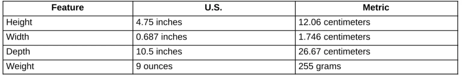
5.2 Physical
See Table 2 for the physical characteristics of the 3192–9P.
Table 2. Physical Specifications
Feature U.S. Metric
Height 4.75 inches 12.06 centimeters
Width 0.687 inches 1.746 centimeters
Depth 10.5 inches 26.67 centimeters
Feature U.S. Metric
Temperature –40 to 149F –40 to 65C
Mounting The 3192–9P ASPR Office Repeater is designed for use in the Charles Indus-tries Span Termination System (STS) Mounting Shelves, or the 340 or 343 mountings. For additional information regarding the Span Termination System refer to Section 319–211–100 (Span Termination System General Description) and Section 319–211–200 (Span Termination System Installation and Applica-tion Engineering).