T3.1
Technology Guides T1 Hardware
T2 Software
T3 Data and Databases T4 Telecommunications T5 The Internet and the Web
T6 Technical View of System Analysis and Design
T E C H N O L O G Y G U I D E
3
Data and Databases
T3.1
File Management
T3.2
Databases and Database Management Systems
T3.3
Logical Data Organization
T3.4
Creating Databases
T3.5
Emerging Database Models
T3.6 Data Warehouses T3.7 Database Management T3.8 Emerging Technologies: IP-based Storage, SANs,
and NAS
T3.9
Data Storage Infrastructure and Management
t03.qxd 01/25/2005 09:41PM Page T3.1
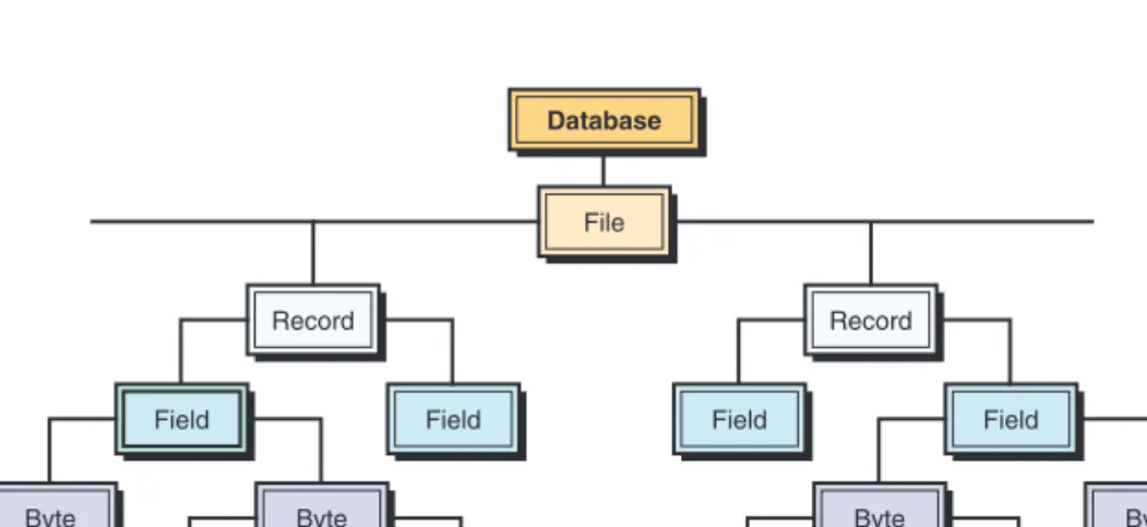
A computer system organizes data in a hierarchy that begins with bits, and pro-ceeds to bytes, fields, records, files, and databases (see Figure T3.1). A bit repre-sents the smallest unit of data a computer can process (i.e., a 0 or a 1). A group of eight bits, called a byte, represents a single character, which can be a letter, a number, or a symbol. A logical grouping of characters into a word, a group of words, or a complete number is called a field. For example, a student’s name would appear in the name field.
A logical group of related fields, such as the student’s name, the course taken, the date, and the grade, comprise a record.A logical group of related records is called a file. For example, the student records in a single course would consti-tute a data file for that course. A logical group of related files would consticonsti-tute a database. All students’ course files could be grouped with files on students’ personal histories and financial backgrounds to create a student’s database.
Another way of thinking about database components is that a record describes an entity.An entity is a person, place, thing, or event on which we maintain data. Each characteristic or quality describing a particular entity is called an attribute (corresponds to a field on a record).
Every record in a file should contain at least one field that uniquely iden-tifies that record so that the record can be retrieved, updated, and sorted. This identifier field is called the primary key. For example, a student record in a U.S. college could use the Social Security number as its primary key. In addition, locating a particular record may require the use of secondary keys. Secondary keys are other fields that have some identifying information, but typically do not identify the file with complete accuracy. For example, the student’s last name might be a secondary key. It should not be the primary key, as more than one student can have the same last name.
Records can be arranged in several ways on a storage medium, and the arrange-ment determines the manner in which individual records can be accessed. In sequential file organization, data records must be retrieved in the same physical sequence in which they are stored. (The operation is like a tape recorder.) In direct or random file organization, users can retrieve records in any sequence, without regard to actual physical order on the storage medium.
T3.1
F
ILEM
ANAGEMENTAccessing Records from Computer Files
FIGURE T3.1 Hierarchy of data for a computer-based file. File Database Record Field Byte Byte Bit Bit Record Field Byte Byte Bit Bit Field Field
T3.1 FILE MANAGEMENT T3.3
(The operation is like a CD drive.) Magnetic tape utilizes sequential file organ-ization, whereas magnetic disks use direct file organization.
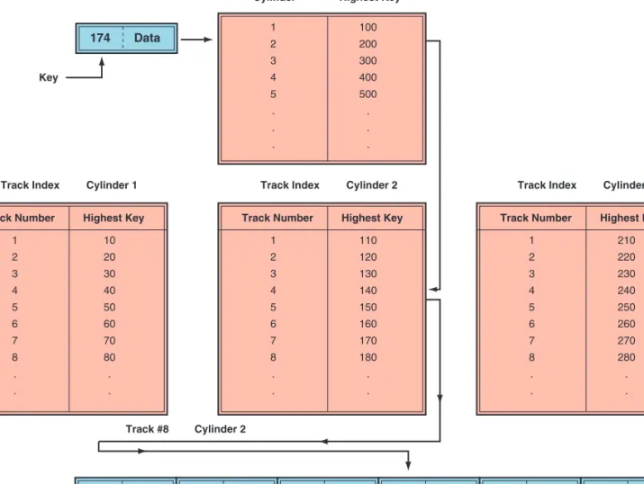
The indexed sequential access method (ISAM) uses an index of key fields to locate individual records (see Figure T3.2). An index to a file lists the key field of each record and where that record is physically located in storage. Records are stored on disks in their key sequence. A track indexshows the high-est value of the key field that can be found on a specific track. To locate a spe-cific record, the track index is searched to locate the cylinder and the track containing the record. The track is then sequentially read to find the record.
The direct file access method uses the key field to locate the physical address of a record. This process employs a mathematical formula called a trans-form algorithmto translate the key field directly into the record’s storage loca-tion on disk. The algorithm performs a mathematical calculaloca-tion on the record key, and the result of that calculation is the record’s address. The direct access method is most appropriate when individual records must be located directly and rapidly for immediate processing, when a few records in the file need to be retrieved at one time, and when the required records are found in no particular sequence. FIGURE T3.2 Indexed sequential access method.
Track Number 1 2 3 4 5 6 7 8 . . Highest Key 10 20 30 40 50 60 70 80 . . Track Number 1 2 3 4 5 6 7 8 . . Highest Key 110 120 130 140 150 160 170 180 . . Cylinder Cylinder Index 1 2 3 4 5 . . . Highest Key
Track Index Cylinder 2 Track Index Cylinder 3 Key
Track Index Cylinder 1
Track #8 Cylinder 2 100 200 300 400 500 . . . Track Number 1 2 3 4 5 6 7 8 . . Highest Key 210 220 230 240 250 260 270 280 . . 171 Data 174 Data
172 Data 173 Data 174 Data 175 Data 176 Data
t03.qxd 01/25/2005 09:41PM Page T3.3
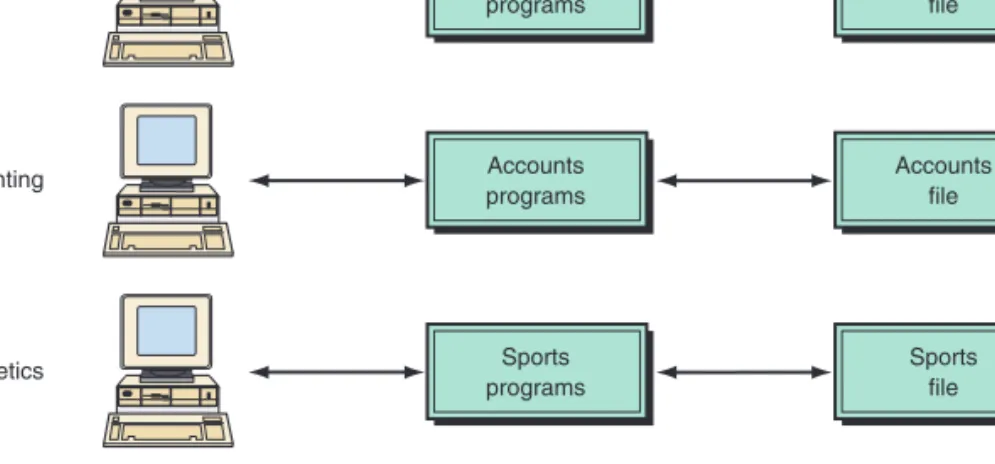
Organizations typically began automating one application at a time. These sys-tems grew independently, without overall planning. Each application required its own data, which were organized into a data file. This approach led to redun-dancy, inconsistency, data isolation, and other problems. Figure T3.3 uses a uni-versity file environment as an example.
The applications (e.g., registrar, accounting, or athletics) would share some common core functions, such as input, report generation, querying, and data browsing. However, these common functions would typically be designed, coded, documented, and tested, at great expense, for each application. Moreover, users must be trained to use each application. File environments often waste valuable resources creating and maintaining similar applications, as well as in training users how to use them.
Other problems arise with file management systems. The first problem is data redundancy: As applications and their data files were created by differ-ent programmers over a period of time, the same data could be duplicated in several files. In the university example, each data file will contain records about students, many of whom will be represented in other data files. Therefore, stu-dent files in the aggregate will contain some amount of duplicate data. This wastes physical computer storage media, the students’ time and effort, and the clerks’ time needed to enter and maintain the data.
Data redundancy leads to the potential for data inconsistency. Data incon-sistencymeans that the actual values across various copies of the data no longer agree or are not synchronized. For example, if a student changes his or her address, the new address must be changed across all applications in the univer-sity that require the address.
File organization also leads to difficulty in accessing data from different applications, a problem called data isolation. With applications uniquely designed and implemented, data files are likely to be organized differently, stored in different formats (e.g., height in inches versus height in centimeters), and often physically inaccessible to other applications. In the university exam-ple, an administrator who wanted to know which students taking advanced courses were also starting players on the football team would most likely not be able to get the answer from the computer-based file system. He or she would probably have to manually compare printed output data from two data files. This process would take a great deal of time and effort and would ignore the greatest strengths of computers—fast and accurate processing.
FIGURE T3.3 Computer-based files of this type cause problems such as redundancy, inconsis-tency, and data isolation.
Problems Arising from the File Environment Class programs Class file Registrar Accounts programs Accounts file Accounting Sports programs Sports file Athletics
T3.2 DATABASES AND DATABASE MANAGEMENT SYSTEMS T3.5
Additionally, securityis difficult to enforce in the file environment, because new applications may be added to the system on an ad-hoc basis; with more applications, more people have access to data.
The file environment may also cause data integrity problems. Data values must often meet integrity constraints. For example, the students’ Social Security data field should contain no alphabetic characters, and the students’ grade-point-average field should not be negative. It is difficult to place data integrity constraints across multiple data files.
Moreover, the shared file environment may have concurrency problems. While one application is updating a record, another application may access that record. As a result, the second application may not get the desired information. Finally, applications should not have to be developed with regard to how the data are stored. That is, applications and data in computer systems should have application/data independence—that is, they should be independent. In the file environment, the applications and their associated data files are dependent on each other.
Storing data in data files that are tightly linked to their applications even-tually led to organizations having hundreds of applications and data files, with no one knowing what the applications did or what data they required. There was no central listing of data files, data elements, or definitions of the data. The numerous problems arising from the file environment approach led to the development of databases.
The amount of data the average business collects and stores is doubling each year. Businesses collect data from multiple sources, including customer-relationship management and enterprise resource planning applications, online e-commerce systems, and suppliers and business partners. The steadily falling price of storage also fuels the data deluge, with the cost of storing 1 Mbyte of data now about 1 percent of what it was 10 years ago. Organizations have found databases to be the optimal way to store and access such huge amounts of data. A databaseis an organized logical grouping of related files. In a database, data are integrated and related so that one set of software programs provides access to all the data, alleviating many of the problems associated with data file envi-ronments. Therefore, data redundancy, data isolation, and data inconsistency are minimized, and data can be shared among all users of the data. In addition secu-rity and data integsecu-rity are increased, and applications and data are independent of one another.
A centralized database has all the related files in one physical location. Centralized database files on large, mainframe computers were the main data-base platform for decades, primarily because of the enormous capital and oper-ating costs of other alternatives. Not only do centralized databases save the expenses associated with multiple computers, but they also provide database administrators with the ability to work on a database as a whole at one loca-tion. Files can generally be made more consistent with each other when they are physically kept in one location because file changes can be made in a super-vised and orderly fashion. Files are not accessible except via the centralized host computer, where they can be protected more easily from unauthorized access
T3.2
DATABASES AND
DATABASE
MANAGEMENT
SYSTEMS
Databases t03.qxd 01/25/2005 09:41PM Page T3.5
or modification. Also, recovery from disasters can be more easily accomplished at a central location.
Like all centralized systems, however, centralized databases are vulnerable to a single point of failure. When the centralized database computer fails to function properly, all users suffer. Additionally, access speed is often a problem when users are widely dispersed and must do all of their data manipulations from great distances, thereby incurring transmission delays.
A distributed databasehas complete copies of a database, or portions of a database, in more than one location, which is usually close to the user (see Fig-ure T3.4). There are two types of distributed databases: replicated and partitioned. A replicated database has complete copies of the entire database in many locations, primarily to alleviate the single-point-of-failure problems of a centralized database as well as to increase user access responsiveness. There is significant FIGURE T3.4 (a)
Cen-tralized database. (b) Dis-tributed database with complete or partial copies of the central database in more than one location.
Users Los Angeles Users New York Users Kansas City Users Chicago Central Location New York Users Los Angeles Los Angeles Users Kansas City Kansas City Central Location New York Users New York (a) (b) New York Users Chicago Chicago
T3.2 DATABASES AND DATABASE MANAGEMENT SYSTEMS T3.7
overhead, however, in maintaining consistency among replicated databases, as records are added, modified, and deleted.
A partitioned database is subdivided, so that each location has a portion of the entire database (usually the portion that meets users’ local needs). This type of database provides the response speed of localized files without the need to replicate all changes in multiple locations. One significant advantage of a par-titioned database is that data in the files can be entered more quickly and kept more accurate by the users immediately responsible for the data. On the other hand, widespread access to potentially sensitive company data can significantly increase corporate security problems. Telecommunications costs and associated time delays can also be major factors.
SPECIALIZED DATABASES. There are many specialized databases, depending on the type or format of data stored. For example, a geographical information database(see Chapter 10) may contain location and other data for overlaying on maps or images. Using this type of data, users are able to view customer and vendor locations spatially instead of simply reading the actual addresses. A
knowledge database(knowledge base, see Chapters 10, 11, and 12) can store decision rules used to evaluate situations and help users make decisions like an expert. A multimedia database (see Chapter 10) can store data on many media—sounds, video, images, graphic animation, and text.
The largest database on the drawing boards is at CERN, the European organ-ization for nuclear and particle physics research in Geneva, Switzerland. CERN is constructing a particle accelerator that will begin operating in 2006, and IT managers at the laboratory are designing a system to collect up to 20 petabytes of data (1 petabyte equals 1000 terabytes) from the accelerator every year, potentially leading to the accumulation of hundreds of petabytes.
The program (or group of programs) that provides access to a database is known as a database management system (DBMS).The DBMS permits an organi-zation to centralize data, manage them efficiently, and provide access to the stored data by application programs. (For a list of capabilities and advantages of the DBMS, see Table T3.1.) The DBMS acts as an interface between application programs and physical data files (see Figure T3.5) and provides users with tools to add, delete, maintain, display, print, search, select, sort, and update data. These tools range from easy-to-use natural language interfaces to complex programming languages used for developing sophisticated database applications. DBMSs are used in a broad range of information systems. Some are loaded on a single user’s personal computer and used in an ad-hoc manner to support individual decision making. For example, Microsoft’s Access and Coral’s Para-dox are desktop DBMSs. Others (such as IBM’s DB2) are located on several interconnected mainframe computers and are used to support large-scale trans-action processing systems, such as order entry and inventory control systems. Still others (such as Oracle’s 9i) are interconnected throughout an organization’s local area networks, giving individual departments access to corporate data. Because a DBMS need not be confined to storing just words and numbers, firms use them to store graphics, sounds, and video as well.
A database management system provides the ability for many different users to share data and process resources. But as there can be many different users, Database
Management Systems
t03.qxd 2/16/05 12:16 PM Page T3.7
there are many different database needs. How can a single, unified database meet the differing requirements of so many users? For example, how can a sin-gle database be structured so that sales personnel can see customer, inventory, and production maintenance data while the human resources department main-tains restricted access to private personnel data?
A DBMS minimizes these problems by providing two views of the database data: a physical view and a logical view. The physical view deals with the actual, physical arrangement and location of data in the direct access storage devices (DASDs). Database specialists use the physical view to make efficient use of stor-age and processing resources.
Users, however, may wish to see data differently from how they are stored, and they do not want to know all the technical details of physical storage. After all, a business user is primarily interested in using the information, not in how it is stored. The logical view, or user’s view, of a database program represents data in a format that is meaningful to a user and to the software programs that
TABLE T3.1 Advantages and Capabilities of a DBMS ● Access and availability of information can be increased.
● Data access, utilization, security, and manipulation can be simplified.
● Data inconsistency and redundancy is reduced.
● Program development and maintenance costs can be dramatically reduced.
● Captures/extracts data for inclusion in databases.
● Quickly updates (adds, deletes, edits, changes) data records and files.
● Interrelates data from different sources.
● Quickly retrieves data from a database for queries and reports.
● Provides comprehensive data security (protection from unauthorized access, recov-ery capabilities, etc.).
● Handles personal and unofficial data so that users can experiment with alternative solutions based on their own judgment.
● Performs complex retrieval and data manipulation tasks based on queries.
● Tracks usage of data.
● Flexibility of information systems can be improved by allowing rapid and inex-pensive ad hoc queries of very large pools of information.
● Application-data dependence can be reduced by separating the logical view of data from its physical structure and location.
FIGURE T3.5 Database management system pro-vides access to all data in the database. Class programs Registrar Accounts programs Accounting Database Class file Accounts file Sports file Sports programs Athletics Database management system
T3.2 DATABASES AND DATABASE MANAGEMENT SYSTEMS T3.9
process that data. That is, the logical view tells the user, in user terms, what is in the database.
One strength of a DBMS is that while there is only one physical view of the data, there can be an endless number of different logical views—one specif-ically tailored to each individual user, if necessary. This feature allows users to see database information in a more business-related way rather than from a technical, processing viewpoint. Clearly, users must adapt to the technical requirements of database information systems to some degree, but DBMS logical views allow the system to adapt to the business needs of the users.
Database management systems are designed to be relatively invisible to the user. To interact with them, however, one needs to understand the procedures for interacting, even though much of their work is done behind the scenes and is therefore invisible or “transparent” to the end user. Most of this interaction occurs by using DBMS languages.
DBMS LANGUAGES. A DBMS contains four major components: the data model, the data definition language, the data manipulation language, and the data dic-tionary. The data modeldefines the way data are conceptually structured. Exam-ples of model forms include the hierarchical, network, relational, object-oriented, object-relational, hypermedia, and multidimensional models. The data definition language (DDL) is the language used by programmers to specify the types of information and structure of the database. It is essentially the link between the logical and physical views of the database. (“Logical” refers to the way the user views data, and “physical” to the way the data are physically stored and processed.) A DBMS user defines views or schema using the DDL. The schema is the logical description of the entire database and the listing of all the data items and the relationships among them. A subschemais the specific set of data from the database that is required by each application.
The DDL is used to define the physical characteristics of each record, the fields within a record, and each field’s logical name, data type, and character length. The DDL is also used to specify relationships among the records. Other primary functions of the DDL are the following:
● Provide a means for associating related data.
● Indicate the unique identifiers (or keys) of the records. ● Set up data security access and change restrictions.
The data manipulation language (DML)is used with a third- or fourth-generation language to manipulate the data in the database. This language con-tains commands that permit end users and programming specialists to extract data from the database to satisfy information requests and develop applications. The DML provides users with the ability to retrieve, sort, display, and delete the contents of a database. The DML generally includes a variety of manipulation verbs (e.g., SELECT, MODIFY, DELETE) and operands for each verb.
Requesting information from a database is the most commonly performed operation. Because users cannot generally request information in a natural lan-guage form, query lanlan-guages form an important component of a DBMS. Struc-tured query language (SQL)is the most popular relational database language, combining both DML and DDL features. SQL offers the ability to perform com-plicated searches with relatively simple statements. Keywords such as SELECT [to specify desired attribute(s)], FROM (to specify the table(s) to be used), and t03.qxd 2/16/05 12:16 PM Page T3.9
WHERE (to specify conditions to apply in the query) are typically used for the purpose of data manipulation. For example, a state legislator wants to send con-gratulatory letters to all students from her district graduating with honors from a state university. The university information systems staff would query the stu-dent relational database with an SQL statement such as SELECT (Stustu-dent Name) FROM (Student Table) WHERE (Congressional District 57 and Grade Point Aver-age 3.4 or higher).
End users often use an approach called query-by-example (QBE) instead of SQL. The user selects a table and chooses the fields to be included in the answer. Then the user enters an example of the data he or she wants. The QBE provides an answer based on the example. QBE hides much of the complexity involved with SQL.
The data dictionarystores definitions of data elements and data characteris-tics such as usage, physical representation, ownership (who in the organization is responsible for maintaining the data), authorization, and security. A data element represents a field. Besides listing the standard data name, the dictionary lists the names that reference this element in specific systems and identifies the individu-als, business functions, applications, and reports that use this data element.
Data dictionaries provide many advantages to the organization. Because the data dictionary provides standard definitions for all data elements, the potential for data inconsistency is reduced. That is, the probability that the same data ele-ment will be used in different applications, but with a different name, is reduced. In addition, data dictionaries provide for faster program development because programmers do not have to create new data names. Data dictionaries also make it easier to modify data and information because programmers do not need to know where the data element is stored or what applications use the data element in order to make use of it in a program.
Data dictionaries are a form of metadata. Metadata is information about information. Metadata matters in the business-to-business world as well. As more corporate transactions are conducted over the Net, each needs metadata so that companies can track the transaction and analyze its success.
Database environments ensure that data in the database are defined once and consistently, and that they are used for all applications whose data reside in the database. Applications request data elements from the database and are found and delivered by the DBMS. The programmer and end user do not have to specify in detail how or where the data are to be found.
DBMS BENEFITS. Database management systems provide many advantages to the organization:
● Improved strategic use of corporate data
● Reduced complexity of the organization’s information systems environment ● Reduced data redundancy and inconsistency
● Enhanced data integrity ● Application-data independence ● Improved security
● Reduced application development and maintenance costs ● Improved flexibility of information systems
T3.3 LOGICAL DATA ORGANIZATION T3.11
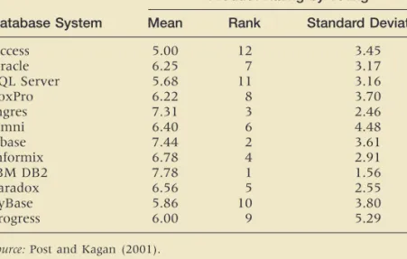
A DBMS is a complex software tool with many features. Its multiple attributes and variations make it difficult for developers to compare products. Moreover, individual developers and administrators have their own personal preferences that are driven by a systems professional’s knowledge investment in the current product. Today, DBMSs are encountering large data sets, multi-dimensional data formats and the use of distributed data inputs. Some scholars discussed the need for data management systems to be designed for the changes in data type and format that would take advantage of faster hardware process-ing capabilities. Others argued that as database systems become more complex in nature, added data management product features will be needed to handle the complexity, which includes object management, knowledge management and multi-faceted issues related to data, objects and knowledge. Actually, certain PC-implemented tools are adding similar features that mimic enterprise-oriented products because user demand is positioning the PC tools due to the issues of rapid development timelines, business process reengineering and the increased processing capabilities of the PC workstation. A survey was done by Post and Kagan (2001) about DBMS in terms of its use and demand for various features of current DBMS regardless of specific implementation. The results are shown in Table T3.2. In another survey, by Bloeman and Brunner, IBM DB2 # UDB (V.8.1) is considered the best product (crmandcontactcentre247.com).
TABLE T3.2 Comparison of Database Management Systems
Product Rating by Voting
Database System Mean Rank Standard Deviation
Access 5.00 12 3.45 Oracle 6.25 7 3.17 SQL Server 5.68 11 3.16 FoxPro 6.22 8 3.70 Ingres 7.31 3 2.46 Omni 6.40 6 4.48 Dbase 7.44 2 3.61 Informix 6.78 4 2.91 IBM DB2 7.78 1 1.56 Paradox 6.56 5 2.55 SyBase 5.86 10 3.80 Progress 6.00 9 5.29
Source:Post and Kagan (2001).
T3.3
LOGICAL
DATA
ORGANIZATION
Just as there are many ways to structure business organizations, there are many ways to structure the data those organizations need. A manager’s ability to use a database is highly dependent on how the database is structured logically and physically. The DBMS separates the logical and physical views of the data, mean-ing that the programmer and end user do not have to know where and how the data are actually stored. In logically structuring a database, businesses need to consider the characteristics of the data and how the data will be accessed.
t03.qxd 01/25/2005 09:41PM Page T3.11
There are three basic models for logically structuring databases: hierarchical, network, and relational. Four additional models are emerging: multidimensional, object-oriented, small-footprint, and hypermedia. (The latter three of these emerg-ing models are explained in Section T3.5.) Usemerg-ing these various models, database designers can build logical or conceptual views of data that can then be physi-cally implemented into virtually any database with any DBMS. Hierarchical, net-work, and object-oriented DBMSs usually tie related data together through linked lists. Relational and multidimensional DBMSs relate data through infor-mation contained in the data. In this section we will present the three basic models. (Others are described in Chapter 10.)
The hierarchical structure was developed because hierarchical relationships are commonly found in many traditional business organizations and processes. The
hierarchical database model relates data by rigidly structuring data into an inverted “tree” in which records contain two elements:
1.A single root or master field, often called a key, which identifies the type, location, or ordering of the records.
2.A variable number of subordinate fields that defines the rest of the data within a record.
As a rule, while all fields have only one “parent,” each parent may have many “children.” An example of a hierarchical database is shown in Figure T3.6.
The strongest advantage of the hierarchical approach is the speed and effi-ciency with which it can be searched for data. This speed is possible because so much of the database is eliminated in the search with each “turn” going down the tree. As shown in Figure T3.6, half the records in the database (East Coast Sales) are eliminated once the search turns toward West Coast Sales, and two-thirds of the West Coast Sales are eliminated once the search turns toward stemware.
Finally, the explicit child/parent relationships in a hierarchical model mean that the integrity of the database is strongly maintained. Every child in a hier-archical database must belong to a parent, and if a parent is eliminated from the database, all its children automatically become children of the parent’s parent.
But the hierarchical approach does have some deficiencies. In the hierarchi-cal model, each relationship must be explicitly defined when the database is created. Each record in a hierarchical database can contain only one key field, and only one relationship is allowed between any two fields. This can create a problem because real-world data do not always conform to such a strict hier-archy. For example, in a matrix organization, an employee might report to more than one manager, a situation that would be awkward for a hierarchical The Hierarchical Database Model FIGURE T3.6 Hierarchical database model. Sales West Coast China Stemware East Coast
T3.3 LOGICAL DATA ORGANIZATION T3.13
structure to handle. Moreover, all data searches must originate at the top or “root” of the tree and work downward from parent to child.
Another significant disadvantage of the hierarchical model is the fact that it is difficult to relate “cousins” in the tree. In the example shown in Figure T3.6, there is no direct relationship between china sales on the East Coast and china sales on the West Coast. A comparison of company-wide china sales would entail two separate searches and then another step combining the search results. The network database model creates relationships among data through a linked-list structure in which subordinated records (called members, not children) can be linked to more than one parent (called an owner). Similar to the hierarchical model, the network model uses explicit links, called pointers,to link subordinates and parents. That relationship is called a set.
Physically, pointers are storage addresses that contain the location of a related record. With the network approach, a member record can be linked to an owner record and, at the same time, can itself be an owner record linked to other sets of members (see Figure T3.7). In this way, many-to-many relation-ships are possible with a network database model—a significant advantage of the network model over the hierarchical model.
Compare Figure T3.7 with Figure T3.6. In Figure T3.7, sales information about china, flatware, and stemware is in one subordinate or member location. Information about each has two parents or owners, East Coast and West Coast. The problem of getting a complete picture of nationwide china sales that exists with the hierarchical model does not occur with the network model. Moreover, searches for data do not have to start at a root—there may not even be a sin-gle root to a network—which gives much greater flexibility for data searches.
The network model essentially places no restrictions on the number of rela-tionships or sets in which a field can be involved. The model, then, is more consistent with real-world business relationships where, for example, vendors have many customers and customers have many vendors. However, network databases are very complex. For every set, a pair of pointers must be main-tained. As the number of sets or relationships increases, the overhead becomes substantial. The network model is by far the most complicated type of database to design and implement.
While most business organizations have been organized in a hierarchical fashion, most business data, especially accounting and financial data, have traditionally been organized into tables of columns and rows. Tables allow quick compar-isons by row or column, and items are easy to retrieve by finding the point of intersection of a particular row and column. The relational database model is FIGURE T3.7 Network database model. The Relational Database Model The Network Database Model Sales West Coast China Stemware East Coast Flatware t03.qxd 01/25/2005 09:41PM Page T3.13
EQA
based on this simple concept of tables in order to capitalize on characteristics of rows and columns of data, which is consistent with real-world business situations. In a relational database, the tables are called relations, and the model is based on the mathematical theory of sets and relations. In this model, each row of data is equivalent to a record,and each column of data is equivalent to a field. In the relational model terminology, a row is called a tuple, and a column is called an attribute.However, a relational database is not always one big table (usually called a flat file) consisting of all attributes and all tuples. That design would likely entail far too much data redundancy. Instead, a database is usually designed as a collection of several related tables.
There are some basic principles involved in creating a relational database. First, the order of tuples or attributes in a table is irrelevant, because their position rel-ative to other tuples and attributes is irrelevant in finding data based on specific tuples and attributes. Second, each tuple must be uniquely identifiable by the data within the tuple—some sort of primary key data (for example, a Social Security number or employee number). Third, each table must have a unique identifier— the name of the relation. Fourth, there can be no duplicate attributes or tuples. Finally, there can be only one value in each row-column “cell” in a table.
In a relational database, three basic operations are used to develop useful sets of data: select, join, and project. The select operationcreates a subset con-sisting of all records in the file that meet stated criteria. “Select” creates, in other words, a subset of rows that meet certain criteria. The join operation com-bines relational tables to provide the user with more information than is avail-able in individual tavail-ables. The project operation creates a subset consisting of columns in a table, permitting the user to create new tables that contain only the information required.
One of the greatest advantages of the relational model is its conceptual sim-plicity and the ability to link records in a way that is not predefined (that is, they are not explicit as in the hierarchical and network models). This ability provides great flexibility, particularly for end users. The relational or tabular model of data can be used in a variety of applications. Most people can easily visualize the rela-tional model as a table, but the model does use some unfamiliar terminology.
Consider the relational database example on East Coast managers shown in Figure T3.8. The table contains data about the entity called East Coast man-agers. Attributes or characteristics about the entity are name, title, age, and divi-sion. The tuples, or occurrences of the entity, are the two records on A. Smith and W. Jones. The links among the data, and among tables, are implicit, as they are not necessarily physically linked in a storage device but are implicitly linked by the design of the tables into rows and columns.
This property of implicit links provides perhaps the strongest benefit of the relational model—flexibility in relating data. Unlike the hierarchical and network models, where the only links are those rigidly built into the design, all the data within a table and between tables can be linked, related, and compared. This ability gives the relational model much more data independence than the hierarchical and network models. That is, the logical design of data into tables can be more independent of the physical implementation. This independence
FIGURE T3.8 Relational database model tables.
Code Name 01 Stemware Division Code Description 01 Director Title
Name Title Code
Smith, A. 01 01 42 Employee
T3.3 LOGICAL DATA ORGANIZATION T3.15
allows much more flexibility in implementing and modifying the logical design. Of course, as with all tables, an end user needs to know only two things: the identifier(s) of the tuple(s) to be searched and the desired attribute(s).
The relational model does have some disadvantages: Because large-scale databases may be composed of many interrelated tables, the overall design may be complex and therefore have slower search and access times (as compared to the hierarchical and network models). The slower search and access time may result in processing inefficiencies, which led to an initial lack of acceptance of the relational model. These processing inefficiencies, however, are continually being reduced through improved database design and programming. Second, data integrity is not inherently a part of this model as with hierarchical and net-work models. Therefore, it must be enforced with good design principles.
OBJECT-RELATIONAL DATABASE SYSTEMS. Object-relational database products are replacing purely relational databases. Object-relational database management systems (ORDBMSs) have some of the capabilities of object-oriented database systems as well as additional unique capabilities. (For details, see Katz, 1998.) The main advantage of the hierarchical and network database models is pro-cessing efficiency. The hierarchical and network structures are relatively easy for users to understand because they reflect the pattern of real-world business rela-tionships. In addition, the hierarchical structure allows for data integrity to be easily maintained.
Hierarchical and network structures have several disadvantages, though. All the access paths, directories, and indices must be specified in advance. Once specified, they are not easily changed without a major programming effort. Therefore, these designs have low flexibility. Hierarchical and network struc-tures are programming intensive, time-consuming, difficult to install, and diffi-cult to remedy if design errors occur. The two structures do not support ad-hoc, English-language-like inquiries for information.
The advantages of relational DBMSs include high flexibility in regard to ad-hoc queries, power to combine information from different sources, simplicity of design and maintenance, and the ability to add new data and records without disturbing existing applications.
The disadvantages of relational DBMSs include their relatively low process-ing efficiency. These systems are somewhat slower because they typically require many accesses to the data stored on disk to carry out the select, join, and proj-ect commands. Relational systems do not have the large number of pointers car-ried by hierarchical systems, which speed search and retrieval. Further, large relational databases may be designed to have some data redundancy in order to make retrieval of data more efficient. The same data element may be stored in multiple tables. Special arrangements are necessary to ensure that all copies of the same data element are updated together.
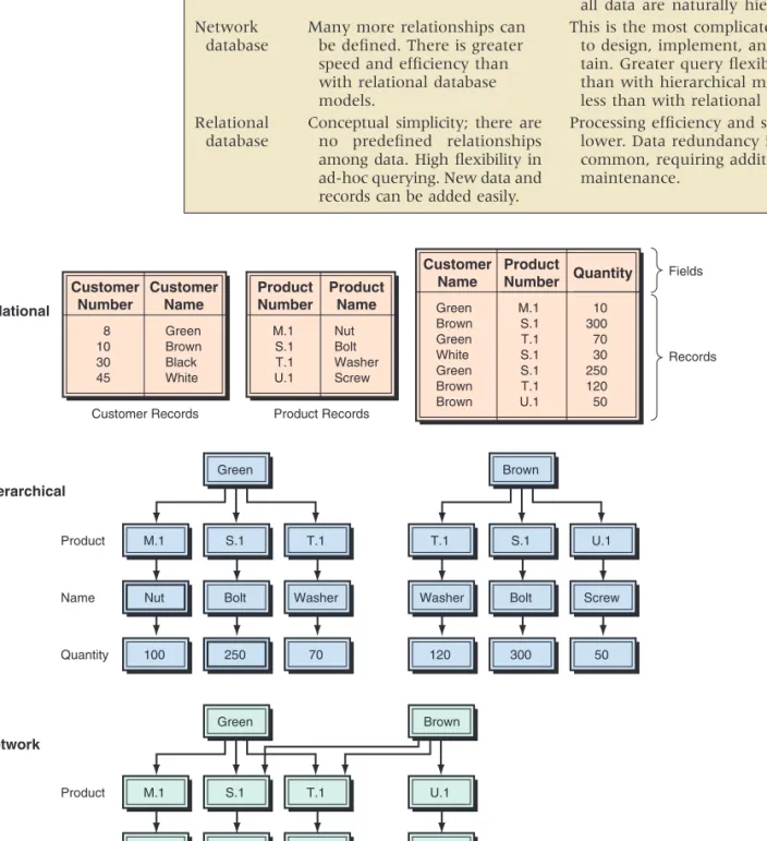
Table T3.3 summarizes the advantages and disadvantages of the three com-mon database models.
Large relational databases may be designed to have some data redundancy in order to make retrieval of data more efficient. The same data element may be stored in multiple tables. Special arrangements are necessary to ensure that all copies of the same data element are updated together. A visual comparison of the three models is shown in Figure T3.9. The lines with arrows in the rela-tional models show the duplication of information.
Comparing the Database Models t03.qxd 01/25/2005 09:41PM Page T3.15
TABLE T3.3 Advantages and Disadvantages of Logical Data Models
Model Advantages Disadvantages
Searching is fast and efficient.
Many more relationships can be defined. There is greater speed and efficiency than with relational database models.
Conceptual simplicity; there are no predefined relationships among data. High flexibility in ad-hoc querying. New data and records can be added easily.
Access to data is predefined by ex-clusively hierarchical relationships, predetermined by administrator. Limited search/query flexibility. Not all data are naturally hierarchical. This is the most complicated model to design, implement, and main-tain. Greater query flexibility than with hierarchical model, but less than with relational mode. Processing efficiency and speed are
lower. Data redundancy is common, requiring additional maintenance. Hierarchical database Network database Relational database
FIGURE T3.9 Database structures. Customer Number 8 10 30 45 Customer Name Green Brown Black White Green M.1 S.1 T.1
Nut Bolt Washer
100 250 70 Customer Records Product Name Quantity a. Relational b. Hierarchical Product Records Product Number M.1 S.1 T.1 U.1 Product Name Nut Bolt Washer Screw Fields Records Customer Name Green Brown Green White Green Brown Brown Product Number M.1 S.1 T.1 S.1 S.1 T.1 U.1 Quantity 10 300 70 30 250 120 50 Green M.1 S.1 T.1
Nut Bolt Washer
100 550 190 Product Name Quantity c. Network Brown T.1 S.1 U.1
Washer Bolt Screw
120 300 50
Brown
U.1
Screw
T3.4 CREATING DATABASES T3.17
Extensible Markup Language (XML) databasescan store whole documents in their native XML format. Such a database makes an archive easier to search by title, author, keywords, or other attributes. Relational databases, in contrast, either convert documents into relational data (stored in tables) or treat them as indiscriminate binary large objects (BLOBs), but it is difficult to find and to retrieve the part of the BLOB that you want. XML database products include Software AG’s Tamino XML Database and Ipedo’s XML Database System. X Query is the XML query language used in these products, which can query a large set of documents based on the name of an author, date filled, subject, or keywords in the document.
To create a database, designers must develop a conceptual design and a physi-cal design. The conceptual design of a database is an abstract model of the database from the user or business perspective. The physical designshows how the database is actually arranged on direct access storage devices.
The conceptual database design describes how the data elements in the data-base are to be grouped. The design process identifies relationships among data elements and the most efficient way of grouping data elements together to meet information requirements. The process also identifies redundant data elements and the groupings of data elements required for specific applications. Groups of data are organized, refined, and streamlined until an overall logical view of the relationships among all of the data elements in the database appears. To pro-duce optimal database design, entity-relationship modeling and normalization are employed. These are described next.
Database designers often document the conceptual data model with an entity-relationship (ER) diagram. ER diagrams consist of entities, attributes, and relationships. In ER diagrams, the boxes represent entities, ovals represent attributes, and the diamonds represent relationships. The attributes for each entity are listed next to the entity.
An entity is something that can be identified in the users’ work environ-ment. In the university example, STUDENT and PROFESSOR are examples of entity. Entities of a given type are grouped in entity classes. An instance of an entity is the representation of a particular entity, so John Smith is an instance of the STUDENT entity, and Sara Douglas is an instance of the PROFESSOR entity.
Entities have attributes, or properties, that describe the entity’s character-istics. In our example, attributes for STUDENT would be Name, IDNumber, and Major. Examples of attributes for PROFESSOR would include Name, Depart-ment, and ClassTaught.
Entity instances have identifiers, which are attributes that identify entity instances. For example, STUDENT instances can be identified with IDNumber. These identifiers are underlined on ER diagrams.
Entities are associated with one another in relationships, which can include many entities. The number of entities in a relationship is the degree of the relationship. Relationships of degree 2 are common and are called binary relationships.
T3.4
CREATING
DATABASES
Entity-Relationship Modeling XML Databases t03.qxd 01/25/2005 09:41PM Page T3.17EQA
There are three types of binary relationships.
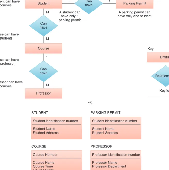
● In a 1:1 (one-to-one) relationship, a single-entity instance of one type is related to a single-entity instance of another type. Figure T3.10 shows STUDENT-PARKING PERMIT as a 1:1 relationship that relates a single STUDENT with a single PARKING PERMIT. That is, no student has more than one parking permit, and no parking permit is for more than one student. ● The second type of relationship, 1:M (one-to-many),is represented by the COURSEPROFESSOR relationship in our example. This relationship means that a professor can have many courses, but each course can have only one professor. See Figure T3.10.
FIGURE T3.10 Entity-relationship diagram model.
(b) Student
A student can have many courses.
A course can have many students.
A course can have only 1 professor.
A professor can have many courses. Parking Permit Can have Can have Can have Course Relationships Entitles Keyfield Key Professor M (a) 1 M M 1 1 A student can have only 1 parking permit
A parking permit can have only one student
STUDENT
Student identification number Student Name Student Address COURSE Course Number Course Name Course Time Course Place PARKING PERMIT
Student identification number Student Name
Student Address
PROFESSOR
Professor identification number Professor Name
T3.4 CREATING DATABASES T3.19
● The third type of relationship, M:M (many-to-many),is represented by the STUDENT-COURSE and SCHEDULE-COURSE relationships in our example. The first part of this relationship means that a student can have many courses, and a course can have many students. The second part of the rela-tionship means that a schedule can have many courses and a course can ap-pear on many schedules (see Figure T3.10).
The ER diagrams are supported by tables. The diagrams help to ensure that the relationships among the data elements in the database are logically struc-tured. When the database includes many files it is difficult to navigate and find data there. The ER acts like conceptual blueprints of the database. It represents all entity relationships. The ER diagrams are often consulted to determine a problem with a query or the complement changes.
In order to use a relational database model effectively, complex groupings of data must be streamlined to eliminate redundant data elements and awkward many-to-many relationships. The process of creating small, stable data struc-tures from complex groups of data is called normalization.
Normalization is a method for analyzing and reducing a relational database to its most parsimonious or streamlined form for minimum redundancy, maxi-mum data integrity, and best processing performance. Specifically, normalization has several goals:
● Eliminate redundancy caused by fields repeated within a file or record, at-tributes that do not directly describe the entity, and fields that can be derived from other fields.
● Avoid update anomalies (i.e., errors from inserting, deleting, and modifying records).
● Represent accurately the item being modeled. ● Simplify maintenance and information retrieval.
Several levels of normalization exist, which build upon each other address-ing increasaddress-ingly specialized and complex normalization problems.
THE NORMALIZATION PROCESS. The concepts of functional dependency and keys are fundamental to normalization. A functional dependencyis a relation-ship between or among attributes, where, given the value of one attribute, we can obtain (or look up) the value of another attribute. For example, in Figure T3.11 Normalization
of Relational Databases
FIGURE T3.11 Lab rela-tion (single key)—first normal form. IDNumber 3244 1697 9611 1234 Major Management Economics Accounting Marketing Lab Inorganic Chemistry Physics Organic Chemistry Physics Fee 25 25 125 25 t03.qxd 01/25/2005 09:41PM Page T3.19
EQA
Many of today’s applications require database capabilities that can store, retrieve, and process diverse media and not just text and numbers. Full-motion video, voice, photos, and drawings cannot be handled effectively or efficiently by either hierarchical, network, or relational databases and the DBMS. For multimedia and other complex data we use special data models.
The most common database models are:
● Multidimensional database. This is an additional database that enables end users to quickly retrieve and present complex data that involve many di-mensions (see Chapter 10).
● Deductive databases. Hierarchical, network, and relational DBMSs have been used for decades to facilitate data access by users. Users, of course, must understand what they are looking for, the database they are looking at, and at least something about the information sought (like a key and some field or attribute about a record). This approach, however, may not be adequate for some knowledge-based applications that require deductive reasoning for searches. As a result, there is interest in what is called deductive databasesystems.
● Multimedia and hypermedia databases. These are analogous to contempo-rary databases for textual and numeric data; however, they have been tailored to meet the special requirements of dealing with different types of media materials (see Chapter 10).
● Small-footprint databases.Small-footprint databases enable organizations to put certain types of data in the field where the workers are located. Whereas laptops were once the only portable machines capable of run-ning a database, advances in technology (e.g., more powerful CPUs and increased memory at lower cost) are enabling handheld devices and smart phones to run some form of an SQL database and to synchronize that mo-bile database with a central database at headquarters. The name comes from the fact that the engines running these databases (e.g., Access) typi-cally are small, and thus the databases do not use a lot of space in memory. Small-footprint databases have replication mechanisms that take into account the occasionally connected nature of laptops and handhelds, that are programmed to resolve replication conflicts among mobile users, and that ensure that data synchronization will survive a low-quality wireless or modem connection. Small-footprint database technology also runs on PDAs (such as those from Palm or Psion) and can be embedded in spe-cialty devices and appliances (like a barcode scanner or medical tool). ● Object-oriented databases.In order to work in an object-oriented
environ-ment, it is necessary to use OO programming and OO databases. This topic is presented next. (Also see the description in Chapter 10.)
T3.5
E
MERGINGD
ATABASEM
ODELSif we know the value of IDnumber, we can find the student’s major. Therefore, we say that a student’s major is functionally dependent on the student’s identifi-cation number, and that the student’s identifiidentifi-cation number is a determinant of the student’s major.
T3.6 DATA WAREHOUSES T3.21
Although there is no common definition for object-oriented database, there is agreement as to some of its features. Terminology in the object-oriented model, similar to object-oriented programming languages, consists of objects, attributes, classes, methods, and messages (see Technology Guide 2).
Object-oriented databases store both data and procedures acting on the data, as objects. These objects can be automatically retrieved and processed. Therefore, the OO database can be particularly helpful in multimedia environments, such as in manufacturing sites using CAD/CAM. Data from design blueprints, photographic images of parts, operational acoustic signatures, and test or quality control data can all be combined into one object, itself consisting of structures and operations. For companies with widely distributed offices, an object-oriented database can provide users with a transparent view of data throughout the entire system.
Object-oriented databases can be particularly useful in supporting temporal and spatial dimensions. All things change; sometimes keeping track of tempo-ral and spatial changes, rather than just the latest version, is important. Related but slightly different versions of an object can easily be maintained in an object-oriented database. Object-object-oriented databases allow firms to structure their data and use them in ways that would be impossible, or at least very difficult, with other database models. An OO database is slow and therefore cannot be used efficiently for transaction-processing-type data. Therefore, as indicated earlier, it is sometimes combined with a relational database.
The hypermedia database model stores chunks of information in the form of nodes connected by links established by the user. The nodes can contain text, graphics, sound, full-motion video, or executable computer programs. Search-ing for information does not have to follow a predetermined organizational scheme. Instead, users can branch to related information in any kind of rela-tionship. The relationship between nodes is less structured than in a traditional DBMS. In most systems, each node can be displayed on a screen. The screen also displays the links between the node depicted and other nodes in the data-base. Like OO databases, this database model is slow.
The Hypermedia Database Model
T3.6
DATA
WAREHOUSES
A data warehouse is an additional database that is designed to support DSSs, EISs, online analytical processing (OLAP), and other end-user activities, such as report generation, queries, and graphical presentation. It can provide an “executive view” of data and a unified corporate picture to the end users by combining the data from many operational systems and incompatible databases without affecting the performance of the running operational systems. It can also provide the decision support system environment in which end users can analyze timely information, and it increases the ability of end users to exploit such information effectively by using data-mining tools or OLAP. The topic is discussed at length in Chapter 10.
However, many companies are struggling to achieve measurable results from their data-warehousing efforts. To be successful, data-warehousing initiatives must adopt two basic concepts: (1) true and comprehensive integrationacross complete data warehousing and business intelligence processes, and (2) a business-centered focus that aims to deliver information that supports business users and addresses business issues. SAP Business Information Warehouse (SAP BW) is the component The
Object-Oriented Database Model t03.qxd 01/25/2005 09:41PM Page T3.21
Database management, outside of purely technical hardware and software con-siderations, consists primarily of two functions: database design and implementation, and database administration.
In designing and implementing databases, specialists should carefully con-sider the individual needs of all existing and potential users in order to design and implement a database, which optimizes both processing efficiency and user effectiveness. The process usually starts by analyzing what information each user (or group of users) needs and then producing logical views for each. These log-ical views are analyzed as a whole for similarities that can lead to simplifica-tion, and then are related so that a single, cohesive logical database can be formed from all the parts. This logical database is implemented with a particular DBMS in a specific hardware system.
Database administrators are IT specialists responsible for the data as well as for ensuring that the database fulfills the users’ business needs, in terms of functionality. User needs, like business in general, do not remain constant. As the business environment changes, and organizational goals and structures react, the database that the firm depends on must also change to remain effec-tive. The computer hardware on which the DBMS software is installed must change to meet changing environments or to take advantage of new technol-ogy. This brings accompanying constraints and/or new opportunities for the DBMS processing performance.
Further, database administrators need to ensure the reliability of databases under their care by managing daily operations, including planning for emer-gency contingencies by providing backup data and systems to ensure minimal loss of data in the event of a disaster. Security is always a data administration concern when there are multiple accesses to databases that contain all the corporate data. Administrators must balance the business advantages of wide-spread access with the threat of corporate espionage, sabotage by disgruntled employees, and database damage due to negligence.
Database administrators also play a significant role in training users about what data are available and how to access them. Finally, administrators are responsible for ensuring that the data contained in the database are accurate, reliable, verifiable, complete, timely, and relevant—a daunting task at best. Otherwise-brilliant business decisions, based on wrong information, can be disastrous in a highly competitive market.
One of the elements of contingency planning is data backup,which is of crit-ical importance to any IT users. Tapes and diskettes are popular data backup media because they are relatively cheap. There are two main methods of backup, full backup and incremental backup. Full backupinvolves keeping a duplicate of
T3.7
DATABASE
MANAGEMENT
of mySAP Business Intelligence (mySAP BI) that delivers enterprise-wide data warehousing.
A data martis smaller, less expensive, and more focused than a large-scale data warehouse. Data marts can be a substitution for a data warehouse, or they can be used in addition to it. In either case, end users can use the warehouse and/or the marts for many applications, such as query, DSS/EIS, reporting, OLAP, knowledge discovery, and data mining. It can increase the productivity of the end users. Also see the description in Chapter 10.
T3.8 EMERGING TECHNOLOGIES: IP-BASED STORAGE, SANs, AND NAS T3.23
the entire database; incremental backup involves keeping just the additional or updated data each time the database is backed up. The incremental backup method is more efficient because of shorter backup time, but it is not as safe as full backup since loss of any one media may make recovery impossible.
Currently, there is a trend for users to back up data using a hard disk—what is called the D2D (disk-to-disk) backupmethod. This method is actually a disk dupli-cation using another hard disk as the backup medium. It is a relatively easier operation than using tapes or diskettes and is now possible because the price of hard disks has fallen a lot lately. A report from QualStar said that 58 percent of respondents had already implemented the D2D backup method, and 25 percent were planning to implement the D2D backup method within the next 24 months (bitpipe.com/detail/RES/1089741706_761.html&src%3Dzdib; see QualStar story).
Nowadays, it is imperative to have the computer systems online in 24 7 365, that is, in nonstop operation, partly because of e-business requirements. A survey done by Ziff-Davis Media in March 2003 found that lost employee pro-ductivity, lost revenue, and damaged company image were the top three conse-quences of a disruption of service. HP’s Business Continuity Storage Solutions are products to meet the need for continuous backup as a result of nonstop opera-tions. HP’s OpenView Continuous Access Storage Appliance (CASA) is a replica-tion applicance for SANs (see secreplica-tion T3.8), in which a new SAN fabric is used to connect different SANs into a single logical pool of storage. HP’s OpenView Storage Data Protector can help companies recover terabytes of data in minutes rather in hours. HP’s StorageWorks Enterprise Virtual Array (EVA), used mainly by data centers, can support heterogeneous environments (e.g., HP OpenVMS, IBM AIX, Microsoft Windows, Novell Netware, and Sun Solaris).
T3.8
E
MERGINGT
ECHNOLOGIES: IP-
BASEDS
TORAGE, SAN
S,
ANDNAS
Storage connected to servers over IP (Internet protocol) networks, also known as IP storage,enables servers to connect to SCSI (small computer system inter-face) storage devices and treat them as if they were directly attached to the server, regardless of the location. IP storage is a transport mechanism that seeks to solve the problem of sending storage data over a regular network in the block format it prefers rather than the file format generally used. IP storage can save money by allowing a company to use its existing network infrastructure for storage. We need to describe what IP-storage attempts to replace, in order to understand why it is an improvement.
Traditionally, data management tasks are handled by tape and disk devices directly attached to each server in the network, called direct attached storage (DAS). Network storage devices are optimized for data management tasks. These devices are attached to the corporate network and can be accessed from networked applications throughout the enterprise. However, sending storage data over the company network can seriously slow network speeds, which will affect applications such as e-mail and Internet access. Enterprises have transi-tioned much of their direct-attached storage (DAS) to networked storage.
Network attached storage (NAS)is an IP-based and Etherbased net-work storage architecture replacing the general-purpose file server with a server running a custom operating system that is optimized for data processing and management. The optimized operating system improves file server performance and supports features of RAID, caching, clustering, etc.
t03.qxd 2/16/05 12:16 PM Page T3.23
A storage area network (SAN) seeks to solve problems associated with sending storage data over regular networks by building a separate, dedicated, high-speed network just for storage devices, servers, and backup systems. It can handle the heavy bandwidth demands of storage data and segregates storage traffic to a network built specifically for storage needs. Communication between the applica-tion server and the storage devices is done using a low-level block-based SCSI-3 protocol. SAN technology is implemented using either a direct point-to-point con-nection or a network switch to a data storage farm. It is both expensive and com-plicated to construct. A SAN requires specially trained management personnel and uses relatively expensive hardware that may be incompatible among vendors.
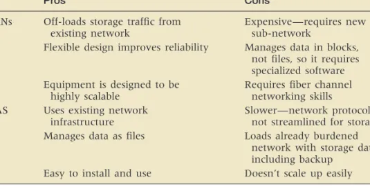
IP or Ethernet networks enable cost-effective SANs to be deployed by a broad market. Since IP storage runs over the existing Ethernet infrastructure, it retains all of the existing networking. This offers interoperability, manageability, compat-ibility, and cost advantages. People can use inexpensive, readily available Ethernet switches, hubs, and cables to implement low-cost, low-risk IP storage-based SANs. The advantages and disadvantages of SANs and NAS are shown in Table T3.4.
Although SANs and NAS have distinct profiles and different environments in which they work best, several companies including DataCore Software (datacore .com/products/prod_home.asp), Nishan Systems (mcdata.com/splash/nishan), Pirus Networks (storagesearch.com/pirusnetw.html), and Vicom Systems (vicom.com/ library/cs_BCBSofTennesseeCompletes.shtml) are taking the advantages of both SANs and NAS by producing software and devices that work with both. New standards are being developed for both types of networked storage. The SCSI-over-IP pro-tocol, called iSCSI, is a new Internet Engineering Task Force (IETF) specification that will let storage systems using SANs data transfer method send SCSI-style blocks of data over an IP network. In addition, a protocol, developed by IETF, called Fiber Channel-over-IP, would allow an enterprise to connect a SAN at one location with a SAN at another over an IP network
TABLE T3.4 Pros and Cons of SANs and NAS
Pros Cons
SANs Off-loads storage traffic from Expensive—requires new existing network sub-network
Flexible design improves reliability Manages data in blocks, not files, so it requires specialized software Equipment is designed to be Requires fiber channel
highly scalable networking skills
NAS Uses existing network Slower—network protocols are infrastructure not streamlined for storage Manages data as files Loads already burdened
network with storage data, including backup
Easy to install and use Doesn’t scale up easily
Data Storage Infrastructure
T3.9
D
ATAS
TORAGEI
NFRASTRUCTURE ANDM
ANAGEMENTThe Direct Access File System (DAFS)protocol is one of the important tech-nologies in data center storage infrastructure. It is a collaborative effort among dozens of vendors that will enable databases, Web servers, e-mail backends, and
T3.9 DATA STORAGE INFRASTRUCTURE AND MANAGEMENT T3.25
Storage Resource Management
a host of other server-resident applications to achieve performance levels that are simply unattainable in the pre-DAFS world.
Another important technology in data center storage is IBM’s Storage Tank storage management system, which combines storage virtualization, enterprise performance, policy-based storage management, and data sharing across het-erogeneous storage systems at a greatly reduced total cost of ownership (TCO) due to more simplified management. IP storage protocols like iSCSI can sim-plify the complexity of SANs while allowing many customers to use a net-working infrastructure with which they are comfortable or at least have already deployed for other uses.
Analysts and consultants estimate that from 50 percent to 70 percent of most companies’ capital technology budget is spent on storage. An analyst at Gartner Group (May 21, 2003) reports that worldwide storage capacity will sky-rocket from 283,000 TB in 2000 to more than 5 million TB by 2005 (hi.is/ ~joner/eaps/wwwgrow4.htm).
In the long term, as part of the data center’s “re-architecting,” the storage infrastructure will be transformed to provide storage automation for resource pooling, provisioning, and policy-driven management. Two strategic storage trends will continue in order to help IT departments: expansion of storage networking, and the continued splitting of the storage pyramid into more categories. Ongoing storage networking trends will include: storage networking intelligence, IP-based storage networking, NAS-SAN convergence, and single-image file systems. Ongo-ing storage pyramid trends will focus on lifecycle content management to deter-mine where in the storage pyramid content in each lifecycle stage should reside. Lifecycle content management builds around the concept of data temperature— that is, hot to cold. Hot data are accessible immediately whenever needed; cold data require some arrangement before they can be used. The trade-offs between hot and cold data are value/cost versus the need for responsive access.
Storage resource management (SRM) and storage virtualization are pieces of software that help manage storage as a whole entity rather than the disparate bits of technology you actually own. It works much like network management devices on corporate networks: The idea is to be able to have a bird’s eye view of everything on the storage networks and allocate storage resources as needed. Fujitsu’s Softek Storage Manager Software ( az.softek.com/en/press/20020219-001.html) is designed specifically to meet the complex storage management requirements. Organizations are creating more information than they can man-age, often doubling storage data each year. On the other hand, many current storage resources are not effectively utilized; only 40% of storage capacity is utilized. Softek Storage Manager has the following features highlights: central-ized management—view and manage storage resources from a single console; meaningful reporting—assess how storage resources are used and identify capacity and performance trends with views at both the physical and logical layer; operation across heterogeneous environments—monitor and manage storage resources across hardware vendors, platforms and operating systems as well as disparate storage topologies; automation of routine tasks—schedule actions based on predefined criteria; business-process views—define and view storage as it applies to the business model; management of storage related costs—assess, utilize and where possible, reduce storage costs; management of service-level requirements—proactively manage service levels as required by the business.
t03.qxd 2/16/05 12:16 PM Page T3.25