Int. J. Production Economics 90 (2004) 129–149
Business process modelling: Reviewand framework
Ruth Sara Aguilar-Sav
en*
!
Department of Production Economics, Linkoping Institute of Technology, SE 581 83 Link. oping, Sweden. Received 18 April 2002; accepted 9 April 2003
Abstract
A business process is the combination of a set of activities within an enterprise with a structure describing their logical order and dependence whose objective is to produce a desired result. Business process modelling enables a common understanding and analysis of a business process. A process model can provide a comprehensive understanding of a process. An enterprise can be analysed and integrated through its business processes. Hence the importance of correctly modelling its business processes.
Using the right model involves taking into account the purpose of the analysis and, knowledge of the available process modelling techniques and tools. The number of references on business modelling is huge, thus making it very time consuming to get an overviewand understand many of the concepts and vocabulary involved. The primary concern of this paper is to make that job easier, i.e. reviewbusiness process modellingliterature and describe the main process modelling techniques. Also a framework for classifying business process-modelling techniques according to their purpose is proposed and discussed.
r2003 Elsevier B.V. All rights reserved.
Keywords: Business process modelling; Enterprise modelling; Modelling tools; Modelling techniques
1. Introduction
Value-adding processes have become more and more the principle of organising the business, rather than a functional hierarchy perspective. Some business processes application examples can be found inSwanson (2003),Artiba (2001),Guinet (2001),Mart!ınez et al. (2001),Al-Mubarak (2003)
and Chan (2002) to mention a few. Hence the modelling of business processes is becoming increasingly popular. Both experts in the field of Information Technology and Business Engineering have concluded that successful systems start with
an understanding of the business processes of an organisation. Furthermore, business processes are a key factor when integrating an enterprise (Aguilar-Saven and Olhager, 2002! ). Conceptual modelling of business processes is deployed on a large scale to facilitate the development of soft-ware that supports the business processes, and to permit the analysis and re-engineering or improve-ment of them.
Even though it was 1960 when Levitt first mentioned the importance of business processes it was not until the last decade that processes have acquired a real importance in enterprise design (Levitt, 1960). Authors such asHarrington (1991), Davenport (1993) and Hammer (1990), among others, promoted the newperspective. The *Tel.: +46-13-285785; fax: +46-13-288975.
E-mail address:[email protected] (R.S. Aguilar-Saven).!
0925-5273/03/$ - see front matterr2003 Elsevier B.V. All rights reserved. doi:10.1016/S0925-5273(03)00102-6
increasing popularity of business process orienta-tion (Hammer and Champy, 1993) has yielded a rapidly growing number of methodologies, and modelling techniques and tools to support it. The process of selecting the right technique and the right tool has become more and more complex not only because of the huge range of approaches available but also due to the lack of a guide that explains and describes the concepts involved. For example, when searching the Internet for guides on business process modelling many thousands of references may be found. There is therefore a need to aid practitioners and academics alike in filtering the wealth of data available on business process modellingso that they do not spend excessive time and effort in undertaking repetitive searches. Instead, they can dedicate themselves to reviewing, understanding and applying many of the asso-ciated concepts and vocabulary.
The aim of this paper is two-fold. On the one hand, it is to reviewa number of business process modelling techniques and tools. On the other hand, it is to propose a framework to classify the techniques according to their purpose as a guide to practitioners and academics who may need to choose from these techniques.
As the research approach followed, the author conducted a literature search on the state of
business process modelling techniques and tools
using as research sources scholarly and trade literature both in scientific journals and material on the web. Searching on the Internet yielded a considerable amount of data although as an initial source of information it was difficult to filter. Web sources are useful for further detailed and specific information on certain techniques or tools and especially in identifying tool availability and potential vendors. With the aid of a number of databases, such asCambridge Scientific Abstracts-Internet Database Service, IEEE Xplore and
Compendex by Engineering Information Inc.,more than 7000 scientific journals and conference proceedings since 1985 were reviewed. The key words used during the search werebusiness process modellingand/orrevieworframework. Most of the papers found are published in journals or proceed-ings related to Information Systems or Computer Sciences. The oldest paper is dated 1993 and
published by ‘‘Information and Software Technol-ogy’’ (Macintosh, 1993).
The focus of the present reviewtherefore is on available techniques and tools explicitly aimed at modelling business processes. These last three words have been the key during the search. Nevertheless, the author is aware that other techniques might exist that are used or that might be used for modelling business processes, which are not referred in the literature. Such techniques have not been identified in this reviewsince all modelling techniques applicable to processes in general are applicable to business processes in particular. However, whether all business process modelling techniques and tools are applicable or not to process modelling is beyond the scope of this paper. The author of this paper confines attention to business processes and the set of modelling techniques applicable to them. In the remainder of this paper the terms ‘‘processes’’ and ‘‘modelling techniques’’ are used in this more limited sense.
This section presents the background of the present research, its aim, and the research approach followed as well as its scope. Section 2 builds the proposal framework used in Section 5 based on the literature survey and highlights some relevant associated concepts. Section 3 describes briefly the main process modelling techniques where some of their key factors are identified. Also some of their strengths and weaknesses are discussed. Section 4 describes some of the generic methodologies with their process modelling cap-abilities. A classification of the techniques de-scribed in Sections 3 and 4 is proposed in Section 5 as a framework to facilitate their selection. Finally, some conclusions and ideas for future research end the paper.
2. Proposal framework and literature survey
To study and understand systems, one con-structs models according to particular view-points and using particular modelling technique.
Kettinger et al. (1997a) present an important overviewof methods, techniques, and tools used in Business ProcessRe-engineering(BPR). As part
of that study a list of some related business process modelling techniques and tools was published. This list does not give detailed descrip-tions of the techniques nor the tools. However, it has been the starting point of the research presented in this paper, which gives a more thorough overviewwith detailed analysis of the mentioned techniques in Kettinger et al. (1997b)
and others.
It is important to identify theuses or purposes of the models when undertaking modelling of any kind. It seems clear that in order to choose the right technique, the modeller must knowthe purpose of the model to be constructed. Different techniques are more suitable to certain purposes, e.g. one thing is a model, which describes the process, and another a model to build a system to control the process.
For instance, Phalp et al. (1999) distinguish between two uses of business process models: one for traditional software development, and another to restructure business processes. In Phalp (1998)
the latter purpose is explained further arguing that
pragmatic approaches are mostly concerned with capturing and understanding processes, while
rigorous paradigms are typically used for analysis of the process. Furthermore, it is argued that ‘ythis suggests a need for different notational
approaches, for different modelling purposes and audiences’ (Phalp, 1998). For software develop-ment process typically diagrammatic notation is required, for capturing a legible and understand-able viewof the business process. Typically the user does not need to play or interact with the model but rather just observe it. When analysing
the business process it is necessary to have more sophisticated mechanisms than qualitative analysis of static diagrammatic models, models that present both dynamic and functional aspects of the process. In these cases users might want a model, which permits him/her more interaction (e.g. it might be simulation) to analyse the question ‘what if’. Finally, in presenting the business process, approaches easy to understand are chosen, again a readily understandable, typically diagrammatic notation is suitable.
Macintosh (1993) defines five levels of process maturity:
1. initial—setting up of processes, 2. repeatable—repeatable processes,
3. defined—documented processes standardised throughout an organisation,
4. managed—measured and controlled processes, and
5. optimising—continuous process improvement. It is easy to imagine that for each level different models are needed. Levels 1–3 require models whose purposes are to describe the process and thus knowledge of the processes to becapturedand
analysed. Levels 4 and 5 require models whose purposes aredecision support in order to monitor
andcontrolprocesses. Macintosh (1993)proposes to define enriched representations of processes and the use of knowledge-based approaches to design newintelligent tools to model business processes. This permits representations of activities including time, resources, causality and authority although no further details are given. According to Macin-tosh business process models can be used explicitly to provide decision support in: analysis, process/ plan instantiation and re-engineering.
Giaglis and Doukidis (1997)emphasise business process models use for change management which may be considered in more general terms as the need to learn, analyse, monitor and control the process and thus needing descriptive and decision support models. The most popular of these approaches include: BPR (Hammer, 1990), Con-tinuous Process Improvement (CPI) (Harrington, 1991), Total Quality Management (TQM) ( Oak-land, 1993), and Organisational Transformation (OT) (Adams, 1984). Other authors such as
Workman et al. (2000) claim too that many different models may be needed to analyse business processes depending on the purpose.
Some of these references aim at defining aspects for a business process model to be complete. e.g.
Workman et al. (2000) present the historical development of enterprise organisation and in-formation technology distinguishing six phases: 1. the functional hierarchy,
2. the functional hierarchy with function oriented automation,
3. the functional hierarchy with shared database on mainframes,
4. the process oriented enterprise,
5. the supply chain oriented enterprise, and 6. the web-enabled agile enterprise.
For each historical development phase they explain the main descriptive aspects arguing that for each phase different models have been needed. For phase 4 they emphasise the need of modelling business processes and they define what they called business model architecture.Giaglis and Doukidis (1997) examine the nature of business processes in the light of modern change management approaches and propose a set of requirements for their modelling as follows:
* Technical requirements: formal modelling,
quantitative modelling, stochastic modelling, model documentation, model adaptability/reu-sability and objective-driven modelling.
* Political/social requirements: Feasibility of
al-ternative designs, communication of models and user friendliness.
These requirements are based on the thought that businesses are essentially ‘‘socio-technical’’ systems. Giaglis and Doukidis (1997) showtoo that simulation can be an invaluable tool for Business Process Modelling (BPM) especially when modelling inter-organisational business pro-cesses. They add three additional requirements for inter-organisational business modelling: modular model design, modular model analysis and model decomposition and integration. The idea is to showfeatures that a business process model should have in order to be classified as performing successfully. All requirements identified by Giaglis et al. are basically meant as guidelines for prospective users or developers of business process simulation models. Hence, we can state that to define model requirements that enable it to be considered complete is function of the purpose of the model. In this sense, Phalp (1998) proposes that models used to analyse business processes for developing software should include expert judgements and heuristics, measurements, form-ality and be executable. In the same context
Toussaint et al. (1997)find three essential aspects of processes that models should present, namely: functional, static and dynamic. Jarzabek et al.
(1995) identify information requirements for business re-engineering to build tools that can support business knowledge acquisition, busi-ness process modelling, performance/quality ana-lysis and anaana-lysis of alternative BPR solutions.
Rajala et al. (1996) introduce a newrequirement, the customer orientation, and propose a new modelling framework, which integrates cus-tomer orientation to business process simulation modelling.
Hommes et al. (2000) give a more general framework to define a business process technique. They identify on the one hand four elements that constitute any individual model: notation, mean-ing, concept relationship and modelling concept, which are called the way of modelling (modelling concepts). On the other hand there are three elements that constitute the way of working: procedure relationship, activity relationship and activity, which describe the procedures by which the models are constructed (modelling procedure). Hommes et al. framework is focused on describing the modelling technique. Whether the resultant model is adequate or not is another question.
Phalp (1998)uses a similar idea, which underlines that notation and method are two important considerations when modelling business processes. Both method and notation will depend on the desired model characteristics, which in turn will depend on the purpose.
Hence, business processes can be described at different levels of detail depending on the abstrac-tion put into analysing the organisaabstrac-tion, which depends in turn on the purpose of the analysis. As a result of the literature review, it was identified that business process models are mainly used either tolearnabout the process,to make decisions
on the process or to develop business process
software. Usually, these purposes relate to some extent to some model characteristics. That is to say, some business process models are better suited depending on the specific purpose. We suggest a very basic classification of business process models giving attention to their level to allowand facilitate model changes in passive and active. Passive means not to allowchanges whereas active means to allowchanges. We combine these two dimensions to classify business process models.
This is represented in a matrix with two axes one for each dimension (see Fig. 1).
Concerning the assessment of the quality of a business process modelling techniqueHommes et al. (2000) present a set of quality properties and procedures to make an objective assessment of these properties possible called Quality-based Mod-elling Evaluation (Q-ME) framework. They link the properties of the model to the way of modelling and working mentioned above. Based on the FRISCO report (Falkenberg et al., 1996) there are three quality properties: expressiveness, arbitrariness and suitability. Other authors such as Barros and Hofstede (1998)andHarmsen (1997)propose other properties such as: comprehensibility, coherence, completeness, efficiency and effectiveness.
In Pandya (1995) a comparison of some methodologies and some modelling tools for business processes is undertaken and a guide showing their suitability in manufacturing man-agement and business processes is proposed. Nevertheless, there is neither a classification of the methodologies and/or tools nor clear distinc-tion between them.
3. Brief description of the main process modelling techniques
Before describing any technique we define what a business process is. According to Davenport (1993) processes are defined as ‘‘structured,
mea-sured sets of activities designed to produce a specified output for a particular customer or market’’. There are so many other definitions but in essence all are the same: processes are relation-ships between inputs and outputs, where inputs are transformed into outputs using a series of activ-ities, which add value to the inputs.
It is beyond the scope of this paper to go into further discussion on the difference between business processes and processes in general. It seems that some authors take them as synon-ymous. For example, in contrast to Davenport,
Hammer (1990) defines businesses process as ‘‘a collection of activities that takes one or more kinds of input and creates an output that is of value to the customer’’. However, an important distinction for the author of this paper is that a business processis related to enterprises,as they define the way in which the goals of the enterprise are achieved and thus they are a subset of the set of processes. According to ENV 12204 (1995) a business process is a partially ordered set of Enterprise Activities which can be executed to realise a given objective of an enterprise or a part of an enterprise to achieve some desired end-result. There are many classifications of business processes too. Often ‘core’ and ‘supportive’ busi-ness processes are distinguished. A core (or primary) process is initiated from outside an organisation, e.g. the chain of activities that realises the delivery of a product to a customer. A supportive (or secondary) process creates the conditions for the primary process to be carried out. This last might be classified in its turn as management processes that control the organisa-tion’s overall strategies and objectives; and sup-port processes, which supsup-port the core processes by offering sufficient resources.
There are many business process modelling techniques, as were mentioned above (PROCESS, 2003). As a result of the literature reviewthe following were found as the most frequently used and therefore they are considered as the main techniques. Sections 3 and 4 are a summary of a longer working paper. For further information, details and references of those sections see Aguilar-Saven (2001)! . The most important characteristics of each technique are discussed below.
Model change permissiveness
Purpose of the model
Fig. 1. Classification framework for business process modelling techniques.
3.1. Flow chart technique
A FlowChart is defined as a formalised graphic representation of a program logic sequence, work or manufacturing process, organisation chart, or similar formalised structure (Lakin et al., 1996). It is a graphical representation in which symbols are used to represent such things as operations, data, flowdirection, and equipment, for the definition, analysis, or solution of a problem. The FlowChart modelling method uses flowcharts to represent processes. It uses a sequential flowof actions and does not support a breakdown of the activities. The FlowChart model is possibly the first process notation. It has frequently been used over many years although there is no exact date for its origin.
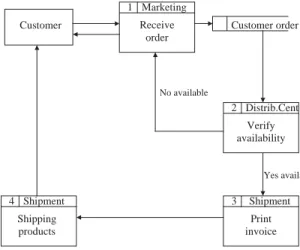
Fig. 2depicts an example of a simple process by using a flowchart. The process starts when a customer makes an order to a company. The company’s Marketing Department receives the order, introduces the information in the informa-tion system at the company and sends the order forward to the Distribution Centre. Distribution Centre verifies the availability of the required products and if they are available they ship the products to the customer together with the invoice, otherwise they inform Marketing of the non-availability so that Marketing may inform the customer.
The main characteristic of FlowCharts is their
flexibility. A process can be described in a wide variety of ways. The standard just gives the notation, but howthe different building blocks are put together is up to the designer of the chart. When we look at a flowchart representation, it is easy to recognise the processes it describes. The real strength of the standard is thecommunication
ability. The FlowChart model is veryeasy to use. It does not take a very long time to drawa sketch of a process.
The weakness of the standard is that it is too flexible. The boundary of the process may not be clear. Flowcharts tend to be very big. Already in the evaluation model, the flowchart can be too large. There is also no difference between main and sub-activities, which makes the chart hard to read. Since there are no sub-layers, it is hard to navigate and it is difficult to find information in the chart. Of course it is easier to followthe course of events, but the risk of getting lost is high. Visualising the process with a flowchart can quickly help identify bottlenecks or inefficiencies where the process can be streamlined or improved. The best use of FlowChart technique is when it is used to deal with processes that need a high level of detail. On the contrary, it is not very good for giving an overview. Usually, there is no natural way of describing responsibilities or performers in the chart. This makes it hard to connect the organisational functions, often referred to as ‘departments’, to activities.
3.2. Data flow diagrams—Yourdon’s technique
Data flowdiagrams (DFD) are diagrams that showthe flowof data or information from one place to another. DFDs describe the processes showing how these processes link together through data stores and howthe processes relate to the users and the outside world. They are used to record the processes analyses as a part of the design documentation ( http://panoramix.univ-par-is1.fr/CRINFO/dmrg/MME/misop025/info.html) and (http://threesl.com/data flow diagrams.htm). A DFD can be seen as a method of organising data from its rawstate. DFDs are the backbone of structured analysis that was developed in the early sixties by Yourdon.Fig. 3depicts the same process as inFig. 2although using DFD notation.
By using DFD, the analyst will be able to specify a process at the logical level. This means that he will be able to describe what a process will do, rather than howit will be done. They are used in discussions between analysts and users as they can be easily understood and verified, and are easy to
Receive Order
Shipping Stock? Print Invoice Distribution Centre Advise Marketing yes no Inform customers
drawand amend. Each process can be broken down into sub-processes at a lower level to show more detail. They only showthe flowof data, not materials. DFD are used in the functional model to specify the meaning of operations and con-straints and showfunctional dependencies. It shows how information enters and leaves the process; what activities change the information; where information is stored within the process, and the organisational function to which the activity belongs.
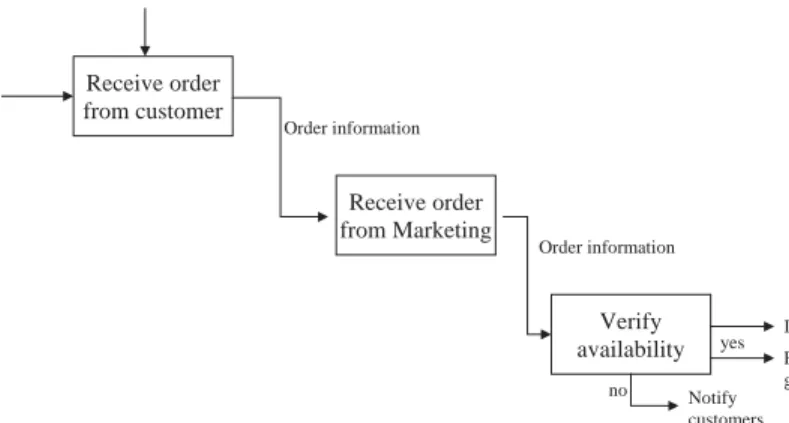
‘Action Diagrams’ are a special case of DFD with simpler notation (Goldkuhl and Rostlinger,. 1988) and permit a contextual analysis. In this sense, ‘action diagrams’ represent an exception of DFD because they introduce data concerning the performer, may showboth information and material flows, and distinguish between knowledge and information.Fig. 4shows the action diagram of the same process of Fig. 2.
3.3. Role activity diagrams—RAD
Role activity diagrams (RADs) are based around a graphic viewof the process from the perspective of individual roles, concentrating on the responsibility of roles and the interactions between them (Holt et al., 1983). Roles are abstract notations of behaviour describing a desired behaviour within the organisation. They
are often organisational functions. They also include software systems, customers and suppliers. RADs provide a different perspective of the process and are particularly useful in supporting communication. They are easy and intuitive to read and understand presenting a detailed viewof the process and permitting activities in parallel. With careful modelling, RADs might define the degrees of empowerment within the business and can also demonstrate howprocesses interact. It can even be used to describe howsoftware systems interact. RADs are, in fact, object state transition diagrams used in object-oriented models. They describe howa role object changes state as a result of the actions and interactions, which occur.
Disadvantages are that the technique explicitly excludes business objects, which are manipulated by the process, as machines or products. The process is presented as a sequence of activities not letting a decomposition of the process, and thus it makes an overviewdifficult.
3.4. Role interaction diagrams—RID
Role interaction diagrams (RIDs) are a graph of a process resulting from the combination of RADs and Jacobson’s object interaction diagrams (Boma, 1996). Activities are connected to roles in a type of matrix. Activities are shown vertically on the left axis and the roles are shown horizontally at the top. Text and symbols are used together in order to represent the process. Horizontal lines
Customer 1 Receive order Marketing Distrib.Cent 2 Verify availability Customer order 4 Shipping products Shipment 3 Print invoice Shipment Yes available No available
Fig. 3. Example of a data flowdiagram.
Contact customer [vendor] Marketing Order from customer
Receive order [vendor] Marketing
Send order [vendor] Marketing
Customer order
Verify availability [controller] Distribution Centre
Shipping products [distributor] Shipment Print Invoice [distributor] Shipment Not
available
or Order from customer
Receive order [vendor] Marketing
Send order [vendor] Marketing
Customer order
Verify availability [controller] Distribution Centre
Shipping products [distributor] Shipment Print Invoice [distributor] Shipment Not
available
or
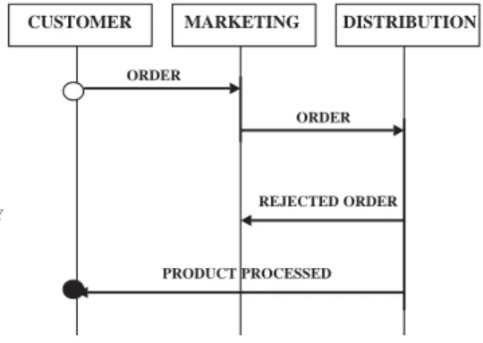
showhuman interactions (Boma, 1996). Fig. 5
shows the same process as inFig. 2using RID. Although slightly more complex than flow diagrams, RIDs are fairly intuitive to understand, easy to read but they tend to be messy, with many arrows pointing left and right and are therefore quite hard to build. Inputs to, and outputs from the activities are not modelled. Therefore, impor-tant information is lost. When editing an existing diagram, it can be hard to insert newactivities or roles. When a newactivity or a newrole is to be inserted, big parts of the diagram have to be moved to allowspace. Since each activity is bound to a performer, the responsibilities are well defined and thus the connection to the organisation is easy to make.
RIDs are not as flexible as flowcharts, for example. They have quite rigid notation. But compared with other modelling techniques, RIDs are nevertheless flexible. Due to their notation and ability to break down activities, very complex processes can be displayed. The best use of RIDs is in workflow design. RIDs are primarily used for processes that involve co-ordination of interrelated activities.
3.5. Gantt Chart
A Gantt Chart (Aguilar-Saven, 2001! ) is a matrix that lists on the vertical axis all the tasks or activities to be performed in a process. Each row contains a single activity identification, which usually consists of a number and a name. The horizontal axis is headed by columns indicating estimated activity duration, skill level needed to
perform the activity, and the name of the person assigned to the activity, followed by one column for each period in the project’s duration. Each period may be expressed in hours, days, weeks, months, and other time units. In some cases it may be necessary to label the period columns as period 1, period 2, and so on. Gantt charts relate a list of activities to a time scale, thus they might be used to represent a process graphically and control its current situation of performance, although its use to analyse a process is limited. They are very simple graphic representations but they do not showclear dependencies between activities.
3.6. IDEF
The Integrated Definition for Function Model-ling (IDEF) is a family of methods that supports a paradigm capable of addressing the modelling needs of an enterprise and its business areas (IDEF, 2003). IDEF’s roots began when the US Air Force, in response to the identification of the need to improve manufacturing operations, estab-lished the Integrated Computer-Aided Manufac-turing (ICAM) program in the mid-1970s. The requirement to model activities, data, and dynamic (behavioural) elements of the manufacturing operations resulted in the initial selection of the Structured Analysis and Design Technique (SADT). SADT is more than a technique. It is a whole methodology to be used as a regimented approach to analysing an enterprise.
The IDEF family is used according to different applications. The most important parts are: IDEF0, IDEF1, IDEF1X, IDEF2, IDEF3, IDEF4 RECEIVE ORDER
CUSTOMER ORDER
CUSTOMER MARKETING DISTRIBUTION
AVAILABILITY CHECK COMMUNICATE NO AVAILABILITY RESERVATION IN STOCK INVOICING ORDER ORDER REJECTED ORDER PRODUCT PROCESSED
and IDEF5. However, for business process mod-elling, the most useful versions are IDEF0 and IDEF3 and therefore they are explained further below.
IDEF0 is a modelling technique used for developing structural graphical representations of processes or complex systems as enterprises. It is used to specify function models, which are ‘‘what do I do?’’ models. These showthe high-level activities of a process indicating major activities and the input, control, output, and mechanisms associated with each major activity. The processes can be further decomposed to showlower-level activities, but at some point the required viewmay require another notation to portray such things as branch control. These models are composed of three types of information: graphical diagrams, text and glossary. These three types are cross-referenced to each other. The major component is the graphical diagram, containing boxes, arrows, box-arrowinterconnections and associated rela-tionships. The IDEF0 format is shown inFig. 6to describe the same process as inFig. 2.
The IDEF0 standard is the most popular process-modelling on the market. The very strict rules in IDEF0 make it suitable for implementa-tion as computer software. By working backwards along the chain from output to inputs, much data and control can be defined. Thus it can be analysed and improved. The hierarchical structure facil-itates quick mapping at a high level. One weakness is the tendency of IDEF0 models to be interpreted
as representing a sequence of activities. The activities may be placed in a left to right sequence within decomposition and connected with the flows. It is natural to order the activities left to right because, if one activity’s output is used as input by another activity, drawing the activity boxes and concept connections is clearer. Thus, without intent, activity sequencing can be em-bedded in the IDEF0 model.
IDEF1 is used for information modelling, which captures conceptual views of the enterprise’s information. IDEF1X is used for data modelling, which captures the logical view of the enterprise’s data and is based on an entity relationship model. It is a design method for logical database. IDEF2 Simulation Model Design method is used to represent time varying behaviour of resources in a manufacturing system. Various commercial products and notations have replaced it.
IDEF3 Process Description Capture method is used to capture behavioural aspects of a process. It allows different views of how things work within an organisation. Unlike IDEF0, IDEF3 has been developed for explicitly describing processes. The former shows what is done within the organisation while the latter shows how things work with it. From domain experts, descriptions are captured in which the precedence and causality relationships between activities and events of the process are shown. IDEF3 consists of two modelling modes: the process flowdescription (PFD), which descri-bes howthings actually work in the organisation,
Receive order from customer Receive order from Marketing Verify availability Invoice Order information Order information Finished goods Check credit yes no Notify customers
and the object state transition description (OSTD), which summarises an object’s allowable transitions in a particular process. It is suitable to model both simple and complex processes due to its decom-position ability.
The basic notation of the IDEF3 method consists of a series of square and oblong boxes, and circles and arcs which link them. Attached to each icon is an elaboration form, which contains a description of that icon, reference label, etc., and a detail of related objects, facts and constrains acting upon it. IDEF3 is used in several areas such as Business Process Engineering (BPE) and Reengineering (BPR), software process definition and improvement, and even in the software development and maintenance.
IDEF4 object-oriented design method was developed to support the object-oriented para-digm. It currently supports design to implement C language applications. IDEF5 method provides a theoretically and empirically well-grounded meth-od specifically designed to assist in creating, modifying and maintaining ontology. Ontology is a part of philosophy whose goal is to divide the ‘‘world’’ into different objects.
3.7. Coloured Petri-net—CPN
Coloured Petri nets is a graphical oriented language for design, specification, simulation and verification of systems. It is particularly well suited for systems that consist of a number of processes, which communicate and synchronise (http://www. daimi.au.uk/PetriNets/tools/quick.html). Colour-ed nets are extendColour-ed Petri nets in which symbols are differentiated by ‘‘COLOURS’’. A CPN model consists of a set of modules which each contain a network of places, transitions and arcs. The graphical representation makes it easy to see the basic structure of a complex CPN model, i.e. to understand howthe individual processes interact with each other. CP-nets have a formal, mathe-matical representation with a well-defined syntax and semantics. This representation is the founda-tion for the definifounda-tion of the different behavioural properties and the analysis methods. The beha-viour of a CPN model can be analysed, either by means of simulation (which is equivalent to
program execution) or by means of more formal analysis methods (which are equivalent to pro-gram verification).
Petri nets were originally developed in the 1960s and 1970s, and they were soon recognised as being one of the most adequate and sound languages for description and analysis of synchronisation, com-munication and resource sharing between concur-rent processes. However, attempts to use Petri nets in practice revealed two serious drawbacks. First of all, there were no data concepts and hence the models often became excessively large, because all data manipulation had to be represented directly in the net structure. Secondly, there were no hierarchy concepts, and thus it was not possible to build a large model via a set of separate sub-models with well-defined interfaces. CP-nets in-corporate both data structuring and hierarchical decomposition without compromising the qualities of the original Petri nets and thus removed these two serious problems.
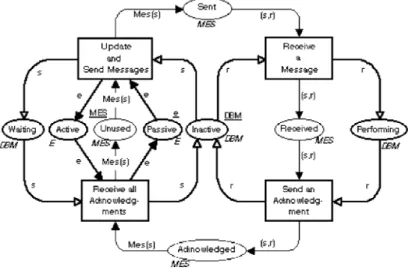
Fig. 7 shows a description of an object’s behaviour states as an example of a CPN. The object considered in the figure is ‘an acknowl-edgement’, which is affected by different activities performed in a process: to send, to receive or to update. According to these activities and a series of rules the object will change: waiting, passive, inactive, etc.
3.8. Object oriented methods
The term object orientation (OO) has different meanings. The history of object oriented program-ming starts with the development of the discrete event simulation language Simula by Dahl and Nygaard in Norway in 1967. Generally, it is used to describe a system that deals primarily with different types of objects, and where the actions one can take depend on what type of object one is manipulating. Thus, OO methods might be defined as methods to model and programme a process described as objects, which are transformed by the activities along the process. The fundamental construct is the ‘‘object’’, which combines both data structure (attributes) and behaviour (opera-tions) in a single entity. Objects may represent real world applications (Rumbaugh et al., 1991).
Benefits of using OO methods are described in (Bruce, 1998).
This method is based on three concepts:objects
that represent a real-world entity. An object has a
state, i.e. one of the possible conditions in which the object may exist represented by the values of the properties (attributes). State changes are reflected by the behaviour, i.e. howan object acts and reacts determined by the set of operations the object can perform on itself, and also knowing its interface, functions and methods. A set of similar objects is calledclass.For example, the attributes for the class animal are having four legs and a tail. Its behaviours is sleeping and eating. Then possible instances or objects of the class animal are cat, elephant, and horse. Finally,messagesare requests for the receiver objects to carry out the indicated method or behaviour and return the result of that action to the sender objects. States change through behaviour when the object receives a message.
Coad and Yourdon (1991) mention seven key motivations and benefits in favour of OO methods instead of using other analysis methods. These are
(1) tackle more challenging problem domains, (2) improve analyst and problem domain expert
interaction,
(3) increase the internal consistency across ana-lysis, design and programming,
(4) explicitly represent commonality between classes and objects,
(5) build specifications resilient to change, (6) reuse OO Analysis and OO Design results,
and
(7) provide a consistent underlying representation for analysis, design and programming. One of the main advantages of OO method is the effectiveness of the process to identify and refine objects.
OO is one of the main methods used for process modelling, especially when the model needs to be enactable. There are many different techniques based on OO. The main techniques used are:
* Booch’s Object Oriented Design (OOD)
Techni-que (Booch et al., 1999) and http://www.slac.-standford.edu/~marino/html/booch/method.html,
* Coad and Yourdon’s OOA/OOD technique
(Coad and Yourdon, 1991;Coad et al., 1995),
* Rumbaught object modelling technique (OMT)
(Rumbaugh et al., 1991),
* Shlaer-Mellor Technique, also known as the
object-oriented systems analysis (OOSA) (http: //cheetah.sdd.sri.com/eliot/ads/shlaer-mellor. html).
Differences among those techniques are basi-cally related to their notation. Therefore, we will explain only one called Unified Modelling Lan-guage (UML), which is considered the standard OO modelling language. Coad and Yourdon’s method precedes UML. For further details on these techniques and OO methodology see
Aguilar-Saven (2001)! .
Unified Modelling Language:UML is a language for specifying, visualizing, constructing and doc-umenting the artefacts of software systems, as well as for business modelling and other non-software systems. UML uses OO methods for modelling. The UML represents a collection of engineering practices that have proven successful in the modelling of large and complex systems, see
UML (2003) and Booch et al. (1999) for further information.
The UML covers conceptual things, such as business processes and system functions, as well as concrete things, such as programming-language classes, database schemas, and reusable software components. The Unified Modelling Language serves as a basis for representing most methods using a common set of modelling constructs and a common notation. It captures the concepts from the OMT, Booch, and OOSE methods, but they hope that other methodologists will adopt it also, so that users can understand models from any method without confusion. The UML can be considered as the standard of the entire object oriented community.1
The UML consists of nine different diagrams, and each diagram shows a specific static or dynamic aspect of a system: Class diagram, describes the structure of a system. The structures are built from classes and relationships. Object diagram, expresses possible object combinations of a specific class diagram. Statechart diagram, express possible states of a class (or a system).
Activity diagram, describes activities and actions taking place in a system.Sequence diagram, shows one or several sequences of messages sent among a set of objects. Collaboration diagram, describes a complete collaboration among a set of objects.
Use-case diagram, illustrates the relationships between use-cases. Each use-case, typically defined in plain text, describes a part of the total system functionality. Component diagram, a special case of class diagram used to describe components within a software system. Deployment diagram, a special case of class diagram used to describe hardware within a software system.
3.9. Workflow technique
In general terms, it is defined as the compu-terised facilitation or automation of a business process, in whole or in part, during which documents, information or tasks are passed from one participant to another for action, according to a set of procedural rules (Fischer, 1995). Workflow is a flowof tasks between computer applications or people in an organisation. Two or more members of a workgroup to reach a common goal can define workflow as well as any task performed in series or in parallel. Workflowis more than a technique to model a process. It is a method to analyse and improve a process, including its modelling. Awork management systemis a system that defines, creates and manages the execution of workflow through the use of software whose order of execution is driven by a computer representation of the work logic (Hollingsworth, 1995).
The workflow development process uses work-flowmodels to capture the relevant information of the processes. This process comprises four stages: Information Gathering, Business Process Model-ling, WorkflowModelModel-ling, and Implementation, Verification and Execution.Fig. 8shows the basic concepts and terms used in workflow and their relationships. Some advantages are: work not forgotten, shorter learning time, data transfer, process improvement, easier to make changes, decentralisation, workflow can be used in combi-nation with other systems. Disadvantages: lost human contact, lack of motivation, feeling controlled.
There is no particular notation for workflow systems. This is due to the existence of a number of workflow languages, which aim to describe and to specify workflow. Each one of these languages uses a specific notation, sometimes a graphical one, to
1A comparison of Object Notations available at: http:// www.cs.queensu.ca/home/stlab/local/UML-paper.html.
describe the processes.Fig. 9, for example, shows a workflow process description using a graphical notation where arrows represent information flow, and squares are workflow activities. These guages can be classified as: Graph-Based lan-guages, Net-Based languages (based on Petri nets) and WorkflowProgramming languages.
4. Generic methodologies
Sometimes when searching business process modelling techniquesnames come up that represent more than a technique. They are generic meth-odologies with process modelling capabilities. Unfortunately those names are often used to point out either the methodology or the modelling technique involved, which may create confusion among practitioners especially to those who are
not familiar with these concepts. For example, Open System Architecture for CIM (CIMOSA) and Integrated Enterprise Modelling (IEM) are two methodologies dealing with enterprise integra-tion. As a part of this task they model enterprise business processes. CIMOSA does this by using its own constructs, which are designed to be easily programmed based on OO methods. IEM model business processes by using diagrams based on IDEF0 and by using EXPRESS language that, again, is based on OO methods. In other words, the techniques used within these methodologies to model business processes are based on what has already been explained although calling them CIMOSA and IEM. This means that e.g. CIMO-SA and IEM are not different or newbusiness process modelling techniques than those included in Section 3. The aim of this section is to clarify and present some of these cases.
4.1. SSADM methodology
Structured systems analysis and design metho-dology (SSADM) is a methometho-dology used in the analysis and design stages of systems development. It is not considered as a particular technique for process modelling. It is considered as a set of procedural, technical and documentation stan-dards for systems development. SSADM adopts a prescriptive approach to information systems
which and/or or during execution are represented by is defined in a composed of which may be used to create and manage is managed by controls
Include one or more Workflow Management System Process Instances Activity Instances Invoked Applications Work Items Sub-processes Manual activity Automated Activity Business process Process Definition Activities
Fig. 8. Concepts of workflow.
A1 A2 A3 A4 A13 A12 A11 A10 A5 A6 A7 A8 A9
development which specifies advance modules, stages and tasks that have to be carried out, the deliverables to be produced and furthermore the techniques used to produce the deliverables. SSADM adopts the Waterfall model of systems development, where each phase has to be com-pleted and signed off before subsequent phases can begin according to Downs et al. (1992) and
Nicholas (2003).
SSADM revolves around the use of three techniques, namely Logical Data Modelling, Data FlowModelling and Entity/Event Modelling. The structure of SSADM consists of five main mod-ules, which are in turn broken down into a complex hierarchy of stages, steps, and tasks: (1) Feasibility Study; (2) Requirements Analysis; (3) Requirements Specification; (4) Logical System Specification; and (5) Physical Design. For the analysis of processes SSADM uses Data Flow Diagrams already explained in Section 3.
4.2. Soft systems methodology
Soft Systems Methodology (SSM) is a metho-dology used to support and to structure thinking about, and intervention in, complex organisational problems. Existing systems, or those yet to be designed, are viewed as social systems, which are derived from human activities. Human activity, behaviour and interaction are all factors that need to be reconstructed, see Soft Systems Methodol-ogy web page: http://members.tripod.com/SSM Delphi/ssm4.html.
The SSM process consists of seven stages. In these stages, one uses relevant techniques and switches between the real world and the concep-tual modelling world where appropriate. These seven stages are: (1) Define the problem situation: unstructured; (2) Express the problem situation; (3) Formulate root definitions; (4) Build concep-tual models; (5) Comparison of stages 2 and 4; (6) Define feasible and desirable changes; (7) Take action to improve the situation. This methodology helps to understand and analyse a process from the human perspective. One of the techniques used to describe a process is calledRich Pictures, which are highly contextual representations of things. They represent some of the richness of the situation
being examined and illustrate issues that will be considered for analysis, reflection and change. They include components such as clients, people involved, tasks performed and environment. This technique is very useful in understanding the interaction of different elements involved in the process and the interaction between processes, although it is not suitable for a structured analysis, or to report a description.
4.3. GRAI methodology
Graph with results and activities interrelated (GRAI) or sometimes called GRAI integrated methodology (GIM) is a methodology developed to address production management decisions in manufacturing systems. As with SSADM, some authors call GRAI a methodology and others call it a technique for process modelling. Actually, strictly speaking GRAI is more than a technique and also GIM, which is a whole methodology (Doumeingts et al., 1996). From the beginning, GIM meant GRAI-IDEF0-Merise. Merise is a method developed in France for the analysis and design of information systems. It is used for designing data models (static models) with En-tity/relationships as formalisms, and enactable models (for instance simulation models) based on Petri nets as formalisms.
Today the GRAI methodology uses four views, namely the functional, physical, decisional and informational systems, to provide the analyst with a generic description of the manufacturing system while focusing on the control aspects of this system. These views permit the building of partial models of the enterprise. Processes are seen from different viewpoints through the four views. For example, the role of the functional viewis to create a simplified representation of the entire system showing the main functions (activities) within the system as well as the interactions between them. GIM uses IDEF0 diagrams to represent the functional view as well as the physical view. For the design of the informational system GIM uses MERISE that is based on Entity/relationships diagrams and Petri nets. Besides GRAI-GIM (Roboam, 1993) provides for its users: a modelling framework, a set of modelling formalisms, and
a structured approach. The analysis of decisions within processes at GRAI GIM is based on GRAI grid and GRAI nets techniques to model processes with focus on the decisional flow. This is a unique feature of GIM. Thus, GRAI grid and GRAI nets permit building process models focusing on responsibilities and decision-making processes being more adequate to be used as a technique for the analysis and design of the process. GRAI grid and GRAI nets techniques were based on IDEF0 when invented.
4.4. Simulation
According toKelton et al. (1996)simulationis a collection of methods and applications to imitate the behaviour of real systems. Simulation can be classified, according to certain characteristics, in deterministic (input data is fixed) or stochastic (input data is randomised), static (system descrip-tions in a mathematical way where time has no role) or dynamic (time plays an essential role) and continuous (systems change their state continu-ously) or discrete (events that occur at separated points of time). Processes seen as systems might be modelled using simulation for the purpose either of understanding the behaviour of the process or of evaluating various strategies for the operation of it either for decision-making or for learning purposes. However, simulation is based on other techniques such as Petri nets or OO methods when modelling systems, so the technique used will depend on the simulating device selected i.e. the tool. Today, there are many available simulation tools that can model all kind of systems, no matter its complexity. Nevertheless, from the user point of viewthe models can be created using the simulat-ing device facilities without mindsimulat-ing which tech-nique is behind it. Likewise, the simulating device facilities give the user the possibility to simulate a process model made with one of the techniques presented in Section 3. This double interaction between simulation and the modelling techniques makes difficult the classification of simulation. However, the author of this paper considers it worth mentioning anyway since simulation repre-sents a great possibility to model a business process. As a disadvantage simulation cannot
model exactly the behaviour of a real system due to the huge number of variables involved. In general, simulation is not used when the system can be modelled analytically because it requires quite a big investment in time and resources.
5. Proposal framework: Classification of process modelling techniques
Practitioners and academics require simple and clear guidelines in order to facilitate the task of choosing the most appropriate technique. This section proposes a classification of the techniques according to their purposes and change model permissiveness. Earlier sections aid in understand-ing the positionunderstand-ing of each technique in this framework. As a result of the analysis carried out in these Sections 3 and 4,Table 1was built to present a summary of the above techniques.
In order to make it easier and faster to viewa relationship between each technique and some of its associated tools available in the marketplace, the table in the Appendix was developed. It is a summary list of the tools in alphabetic order. The table is based on information fromAguilar-Saven! (2001) which in turn is based on the information presented by Kettinger et al. (1997a) and com-pleted with information from vendors Web-based marketing material.
The techniques presented in Sections 3 and 4 can be classified according to the two dimensions described in Section 2, namely purpose of the model and model change permissiveness. Fig. 10
shows the resultant framework. The framework classification together withTable 1is proposed to be used to choose among the business process modelling techniques. The idea is to provide users with a framework that helps them to decide which, among the explained techniques, is the one they should apply for a specific case.
Process modelling techniques might be used either to develop software that supports processes or to analyse the processes themselves. In both cases sometimes a model is required todescribethe process either as a data capture or a presentation exercise. This aids learning about the process. Sometimes models are needed tomake decisionson
AR
TI
CL
E
IN
P
RE
S
S
Technique Description Attributes Characteristics Strengths and Weakness
User perspective Modeller perspective
Strength Weakness Strength Weakness
Flow Chart
Graphic representation
Flowof actions Not sub-layers Great details No overview
Communication ability
Can be too large Flexibility quick, simple No method available Different notations DFD Descriptive diagrams for structured analysis
Flowof data Explains logical level sub-layers Easy to understand Only flowof data is shown Easy to verify and draw
RAD Graphic view object state transition diagrams Flowof individual roles Detailed view Degree of empowerment No overview Supports communication Intuitive to read Not possible to be decomposed Include business objects Different notations RID Matrix representation of processes for co-ordination of activities Flows of activities and roles Inputs to and outputs from are not modelled Performers are included Intuitive to understand Important information is not included Rigid notation Complex processes can be displayed Difficult to edit an existing diagram Hard to construct Gantt Chart Matrix representation Flowof activities and duration Relate activities to time Easy overview representation and control of performance
Not aid for analysis or design Simple No clear representation of dependencies IDEF0 Structural graphical representation, text and glossary
Flows of activities, inputs, outputs, control and mechanisms Based on SADT Sub-layers The most popular Shows inputs, outputs, control and mechanisms overviewand details Trend to be interpreted only as a sequence of activities Roles are not represented Strict rules Possible to build a software Quick mapping IDEF3 Behavioural aspects of a system Precedence and causality relationships between activities Allows different views Process flow descriptions and object state transition description diagrams Sub-layers Easy to understand dynamic aspects in a static way Many partial diagrams to describe a process
Strict rules and notation Possible to build a software
Need lot of data Time consuming when modelling complex systems R.S. Aguilar-Sav ! en / Int. J. Product ion Economics 90 (2004) 129 – 149
AR
TI
CL
E
IN
P
RE
S
S
decomposition each other semantics Possible to build a software Data concepts Object Oriented Methods Describe a system with different type of objects Object’s structure and behaviour Three concepts: objects, classes and messages There are many modelling techniques based on OO Enactable model to control and monitor processes Model are excessively large and detailed Fragmented information Internal consistency across design, analysis and programming Possible to build a software
Need lot of data Time consuming when modelling Complexity Workflow Computerised facilitation or automation of a business process Flowof information, tasks and procedural rules Flowof tasks between computers and people Decentralised Easy to analyse Shorter learning time Possible build a software Data transfer Easy to make changes Lack of a particular notation Many languages Rich Pictures Contextual representation of things Represent process human problematic Represent some of the richness of the process being examined Support communication and understanding of the process It is not structured approach Easy to illustrate components as clients, people, tasks and environment Lack of a particular notation GRAI grid and GRAI nets Descriptive diagrams of the process focused on decisions Decision making process and flow of activities
Sub-layers Distinction between period and event driven activities
Shows inputs, outputs, control and mechanisms, overviewand details Many partial diagrams to describe a process Strict rules and notation Possible to build a software
Need lot of data Time consuming when modelling Complexity R.S. Aguilar-Sav ! en / Int. J. Product ion Economics 90 (2004) 129 – 149 145
the design, or on the development (changes, improvements or re-design) of processes. The aim in this case is to develop adequate business processes, so the purpose of these models is for analysis. Sometimes however when executing a process somedecisionsmight be required to ensure its correct performance. Hence the need for some process models tocontrol and monitorprocesses as well as to give right information in order to support those decisions. Interactive models are often of great use here. Finally, for the software development process, which supports business processes, enactable models are essential for programming. Therefore, uses or purposes of business process modelsmight be divided into four main categories as follows:
(1) descriptive models for learning;
(2) descriptive and analytical models for decision support to process development and design; (3) enactable or analytical models for decision
support during process execution, and con-trol; and
(4) enactment support models to Information Technology.
They will constitute the horizontal axis of our framework (seeFig. 10).
Another specific model characteristic is consid-ered important for the present proposal frame-work always looking to make the frameframe-work as
general and simple as possible: change model permissiveness. This characteristic pays attention to the level to allowand facilitate model changes. Analysis of the techniques identified has indicated that some of the models developed may be classified aspassive. That is, they do not have the capability to allowthe user to interact with, or change them without totally remodelling the process. In contrast, other models allowusers to make changes, or are dynamic themselves. Exam-ples include simulation and enactable models. Such models may be classified as active. Hence, the distinction between active and passive models is what we call change model permissiveness, and constitutes the vertical axis of our framework (see
Fig. 10).
6. Conclusion and further research
Business process modelling is a much-researched field but is neither well structured nor classified. There exists considerable confusion on terminol-ogy. For example, OO has different interpretations and definitions. Some consider OO as a general methodology for process modelling. Others how-ever may consider it a philosophy that shows how the ‘‘real world’’ behaves or may consider it to be just a simple technique. The same applies to SSADM, Workflowand GRAI. Hence there is a need to clarify, classify, organise and structure this field of research. The reviewand resultant frame-work presented in this paper is an attempt to fill this gap.
A classification framework to aid selection of process modelling techniques based on the purpose and type of model has been proposed. However, further research is required in order to classify the techniques according to other criteria such as experience, difficulties in use and suitability. Comparisons among the techniques would be of great help too.
There is still lack of a general framework on what a business process modelling technique must include to be successful. Some efforts carried out in this sense have given partial results so far. However, when integrating an enter-prise, business process modelling techniques and
Model change permissiveness
Ac tiv e P assiv e Descriptive for learning DS for process develop/design DS for process execution IT Enactment support
Purpose of the model
Role Activity Diagram IDEF 0 Role Interaction Diagram
Flow Chart DFD - Yourdon
SSM-Rich Pictures
Coloured Petri nets
IDEF 3 Booch’s OOD
Coad andYourdon’s OOA/OOD Rumbaught OMT Shlaer-Mellor OOT UML Gantt Chart Gantt Chart IDEF 3 Workflow GRAI-GIM
Fig. 10. Classification framework to select among business process modelling techniques.
tools cannot in themselves provide ‘the solution’. They are an aid to business analysts to design and manage the processes, whose understanding is an essential function of communication and consensus in an enterprise. Hence, the capa-bility of a tool to support communication and enhance understanding is of the highest importance.
Further research is required to analyse in detail the available process modelling tools in order to give users a complete description of the purpose, scope and use of each tool. This will also
provide a comparative assessment and aid in their selection.
Appendix
Business process modelling techniques and their associated tools is given inTable 2. The purpose of this table is limited to inform readers about available tools. It is not intended to be a guide for users to select the appropriate tool. In this sense further research is needed.
Table 2
Technique Tools/Trademarks
Flowchart ABC Flow Charter 4.0, ABC Graphics Suite, ABT Project Workbench, AWD and Workflow Analyzer, Bench Marker Plus, BPM, Business Object Modelling Workbench, Cap Web-Flow, CLEAR, COI-Business Flow, CORE, COSA, CSEWorkflow5.0, Docu Flow, EPM SuiteFlowMaker, FlowPath, FlowPATH IMAGEWorks, Flowcharter, Flowmark, Form Flow, Free Flow, GOOFEE Diagrammer, IBMBusiness Process Modeler, Ithink (HPS), Jet Form Server, MAXIM, Net Prophet, OCTOFlow, Optix Workflow, PAVONE Group Flow, PFTamptrade, Power Flow, Power Flow Team Flow Process Wise, Pro Model, Process Charter, Process Maker, RKB Work Frame, SA/BPR Professional, Smart Flow98, Vectus, Visual Thought, Work FlowAnalyzer, Work FLOW SQL, Work Flow.2000, Work Flow.2020, Work Xpert, Workflow FONT , CESymbolmiddot
FONTBPR, WorkflowModeler, Workflow.BPR, Trampolin. DFD—
Yourdon
ARIS-Tools, CASE Tool, 4Keeps, BONAPART, GRADE, INCOME, IEW, Paradigm Plus, Popkins Systems Architect, Softwarethrough Pictures SE , ProcessWise, With Class 98, Graphics Toll
Role activity diagrams RAD
RADitor (Co-ordination Systems Ltd.) Role interaction
diagram RID
RADitor (Co-ordination Systems Ltd.)
Gantt chart ABT Proyect Workbench, PFTamptrade, Project Scheduler7, Team Flow, Workflow BPR
IDEF 4Keeps, AI0WIN, BPWin, Business Object Modelling, orkbench, CORE, Design IDEF, Design Leverage, IDEF Tools, Popkins Systems Architect, Pro CAP Pro SIM, Process Maker, SA/BPR Professional and Workflow Modeler.
Petri-net–CPN Desigh CPN, UNCOME, PACE, Process Maker and Process Weaver Booch OOD 4Keeps, lass Designer, Paradigm Plus,
Softwarethrough Pictures Booch, With Class 98 Coad/Yourdon
OOA/OOD
4Keeps, Paradigm Plus, Together C , With Class 98 Rumbaught
OMT
4Keeps, Paradigm Plus, Select Enterprise Shlaer-Mellor
OOM
4Keeps, Bridge Point Automation Tools, Paradigm Plus, SES/objectbench, With Class 98
UML OOM 4Keeps, Class Designer, COOLJex, Innovator, j-vision, Javision, LOREx2 for Java, Magic DrawUML, Object Plant, Objecteering, Paradigm Plus, Pragmatica, Real-time Studio, Rhapsody, SDT, Soft Modeler Business, Softwarethrough Pictures UML, Together C, Together J, Visual UML, With Class 98
WorkflowViewWorkflow, ABSI-Docss, Action Request System, Action WorkflowAnalyst, Action WorkflowApplication Builder, Action WorkflowEnterprise Series, Action WorkflowWorkflowManager, ARIS, TIWorkflow Distributor AWD, AWD and WorkflowAnalyzer, Beyond Mail, BONAPART, Business Object Modelling Workbench, Cap Web-Flow, CMSWorkflow, COI-Business Flow, Computron Workflow, COOL, COSA,
References
Adams, J.D., 1984. Transforming Work. Miles River Press, Alexandria, VA, USA.
Aguilar-Saven, R., 2001. Business process modelling techniques! and tools. Department of Production Economics. WP291, Linkoping Sweden..
Aguilar-Saven, R., Olhager, J., 2002. Integration of product,! process and functional orientations: Principles and a case study. Preprints of the International Conference on Advanced Production Management System, APMS 2002, IFIP, September, The Netherlands.
Al-Mubarak, F., 2003. A simulation study of focused cellular manufacturing as an alternative batch-processing layout. International Journal of Production Economics 83 (2), 123–138.
Artiba, A., 2001. Productive systems: Strategy, control, and management. International Journal of Production Econom-ics 74 (1–3), 1–4.
Barros, A.P., Hofstede, A., 1998. Towards the construction of workflow suitable conceptual modelling techniques. Infor-mation Systems Journal 8 (4), 313–337.
Booch, G., Rumbaugh, J., Jacobson, I., 1999. The Unified Modelling Language User Guide. Addison-Wesley, USA. Boma, 1996. Process definition, available athttp://www.sesh.
com/procdef.html.
Bruce, P.D., 1998. Real-Time UML, Developing Efficient Objects for Embedded Systems. Addison-Wesley, USA. Chan, M., 2002. A framework to develop an
enter-prise information portal for contract manufacturing. International Journal of Production Economics 75 (1–2), 113–126.
Coad, P., Yourdon, E., 1991. Object-Oriented Analysis, 2nd ed. Prentice-Hall, Englewood Cliffs, NJ, USA.
Coad, P., North, D., Mayfield, M., 1995. Object Models: Strategies, Patterns and Applications. Prentice-Hall, Engle-wood Cliffs, NJ, USA.
Davenport, T.H., 1993. Process Innovation: Reengineering Work through Information Technology. Harvard Business School Press, Boston, MA, USA.
Doumeingts, G., et al., 1996. State of the art on models, architectures and methodologies. In: Bernus, P., Nemes, L., Williams, T.J. (Eds.), Architectures of Enterprise Integra-tion. IFIP/Chapman & Hall, London, pp. 223–255. Table 2 (continued)
Technique Tools/Trademarks
CSEWorkflow5.0, Designer2000, Docu FlowDocument Manager, Documentrix Workmanager, EDI36, EDI38, EDI400, EDIe Qmail, Engineering WorkflowSystem, Ensemble, Enterprise Analyst, Entire Workflow, EPM Suite, Extend BPR, Fabasoft Components, File Net Work Flow, Flo Ware, FlowMaker, FlowMan, FlowPATH IMAGEWorks, FLOWBuilder, Flowmark, Form Flow, FORO, FYI, FYI Workflow, Group Wise, IBIsys, IBMBusiness Process Modeler, IBS WorkflowManager, Image Fast, Image Master, In Concert, Inter Office, Jet Form Server, Key Workgroup, Keyflow, Lifeflow, Life FLOW, Link Works Team Links, Linkworks, Livelink Intranet, MAVIM 3, Memo, Message Driven processor MDp, Metaphase 2.0, MetaviewFOLDERS, METEOR, Metis, Navigator 2000Document Management Systems Navigato, Navigator 2000Workflowm, Nova Manage, OCTOFlow, ODMS, Office.IQ, Open Image, OPENworkflow, Optix Workflow, PANOVE Group Flow, Plexus Flo Ware, Power Flow, Power Flow Team Flow Process Wise, Power Work, Process IT, Protos, Radica, Regata, Route Builder Omni Desk, SAP Business Workflow, Smart Flow 98, Smart Stream, SPARKS G2, Struct Ware, The Vantive System, Ultimus, Viewstar Workbench, Win Work, Wizdom Works, Work Fast, Work Flow Analyzer, Work MAN, Work Party, Work Xpert, WorkflowFONT FACESymbolmiddot, FONTBPR, Workflow.BPR, WORKlogik TM, World Wide Web Flow W4, Xworkflow
SSADM 4Keeps, SSADM Soft System
Methodology
Group Decision Support System (GDSS), Group system (Ventura Corp) GRAI GIM IMAGIM, CAGIM (Computer Aided GIM), DGRAI
Simulation AWD and WordflowAnalyzer, BONAPART, BPSimulator Template, Business Object Modelling Workbench, Business Process Analyzer Bwise Toolkit, CABRE-Witness Cinderella SDL, CLEAR, Clear Process, Design CPN, Design Leverage Dress Rehearsal, EPM Suite, First STEP, Flowcharter GRADE HITSoft BIZ, HOCUS, i-think Ii-think, Live Analyst, METIS, Micro SAINT Object GEODE, Optima, Optima Express, Oracle Process Manager, PACE, PAVONE Group Flow, Powersim, ProModel, ProModel2.0, Process Charter Prophesy, PROSIM Process Modeling Software, Quick CRC, RDD-100, SES/Workbench, SIMAN amp ARENA, SIMPROCESS, Soft Modeler Business, SPARKS G2, Statemate Magnum, Struct Ware, Surveywin Taylor II, TI BDF, Vectus, Vensim, Witness, WorkflowAnalyzer, WorkflowFONT FACESymbolmiddotFONTBPR, WorkflowBPR