A general model of software architecture design derived
from five industrial approaches
Christine Hofmeister
a, Philippe Kruchten
b,*, Robert L. Nord
c, Henk Obbink
d,
Alexander Ran
e, Pierre America
daLehigh University, Bethlehem, PA, USA
bUniversity of British Columbia, 2332 Main Mall, Vancouver, BC, Canada V6T 1Z4 cSoftware Engineering Institute, Pittsburgh, PA, USA
dPhilips Research Labs, Eindhoven, The Netherlands eNokia Research Center, Cambridge, MA, USA
Received 1 January 2006; received in revised form 8 May 2006; accepted 12 May 2006 Available online 5 July 2006
Abstract
We compare five industrial software architecture design methods and we extract from their commonalities a general software archi-tecture design approach. Using this general approach, we compare across the five methods the artifacts and activities they use or recom-mend, and we pinpoint similarities and differences. Once we get beyond the great variance in terminology and description, we find that the five approaches have a lot in common and match more or less the ‘‘ideal’’ pattern we introduced. From the ideal pattern we derive an evaluation grid that can be used for further method comparisons.
2006 Elsevier Inc. All rights reserved.
Keywords: Software architecture; Software architecture design; Software architecture analysis; Architectural method
1. Introduction
Over the last 15 years a number of organizations and indi-vidual researchers have developed and documented tech-niques, processes, guidelines, and best practices for software architecture design (Bass et al., 2003; Bosch, 2000; Clements et al., 2002a; Clements and Northrop, 2002; Dikel et al., 2001; Garland and Anthony, 2002; Gomaa, 2000). Some of these were cast and published as architecture design methods or systems of concepts, pro-cesses and techniques for architecture design (Hofmeister et al., 1999; Kruchten, 2003; Obbink et al., 2000; Ran, 2000).
Since many of the design methods were developed inde-pendently, their descriptions use different vocabulary and appear quite different from each other. Some of the differ-ences are essential. Architecture design methods that were developed in different domains naturally exhibit domain characteristics and emphasize different goals. For example architectural design of information systems emphasizes data modeling, and architecture design of telecommunica-tion software emphasizes continuous operatelecommunica-tion, live upgrade, and interoperability. Other essential differences may include methods designed for large organizations vs. methods suit-able for a team of a dozen software developers, methods with explicit support for product families vs. methods for one of a kind systems, etc.
On the other hand, all software architecture design meth-ods must have much in common as they deal with the same basic problem: maintaining intellectual control over the design of software systems that: require involvement of
0164-1212/$ - see front matter 2006 Elsevier Inc. All rights reserved. doi:10.1016/j.jss.2006.05.024
*
Corresponding author. Tel.: +1 604 827 5654.
E-mail addresses:[email protected](C. Hofmeister), [email protected](P. Kruchten),[email protected](R.L. Nord),[email protected]
(H. Obbink), [email protected] (A. Ran), [email protected](P. America).
and negotiation among multiple stakeholders; are often developed by large, distributed teams over extended periods of time; must address multiple possibly conflicting goals and concerns; and must be maintained for a long period of time. It is thus of significant interest to understand the commonalities that exist between different methods and to develop a general model of architecture design. Such a model would help us better understand the strengths and weaknesses of different existing methods as well as provide a framework for developing new methods better suited to specific application domains.
With this goal in mind, we selected five different meth-ods: Attribute-Driven Design (ADD) Method (Bass et al., 2003), developed at the SEI; Siemens’ 4 Views (S4V) method (Hofmeister et al., 1999), developed at Sie-mens Corporate Research; the Rational Unified Process 4 + 1 views (RUP 4 + 1) (Kruchten, 1995, 2003) developed and commercialized by Rational Software, now IBM; Business Architecture Process and Organization (BAPO) developed primarily at Philips Research (America et al., 2003; Obbink et al., 2000), and Architectural Separation of Concerns (ASC) (Ran, 2000) developed at Nokia Research. We also assembled a team of people who have made signif-icant contributions to developing and documenting at least one of the methods. Through extensive discussions focused on how typical architecture design tasks are accomplished by different methods, we have arrived at a joint under-standing of a general software architecture design model that underlies the five methods. In this paper we document our understanding of what seems to be fundamental about architecture design.1
This paper is organized as follows. We introduce the five contributing methods in Section 2. Then in Section3 we present a general model of architecture design. Section 4
describes the five contributing methods using terms and concepts of the general model, and discusses the common-alities and differences between the contributing methods. Section5describes how other software architecture meth-ods can be compared against the general model using a grid, and applies the grid to another published method. Section6discusses related work, Section7proposes future work, and Section8concludes the paper.
2. Five industrial software architecture design methods 2.1. Attribute-Driven Design
The Attribute-Driven Design (ADD) method (Bass et al., 2003), developed at the SEI, is an approach to defin-ing software architectures by basdefin-ing the design process on the architecture’s quality attribute requirements.
In ADD, architectural design follows a recursive decom-position process where, at each stage in the decomdecom-position,
architectural tactics and patterns are chosen to satisfy a set of quality attribute scenarios (seeFig. 1). The architecture designed using the ADD method represents the high-level design choices documented as containers for functionality and interactions among the containers using views. The nature of the project determines the views; most commonly one or more of the following are used: a module decompo-sition view, a concurrency view, and a deployment view. The architecture is critical for achieving desired quality and business goals, and providing the framework for achieving functionality.
Architects use the following steps when designing an architecture using the ADD method:
1.Choose the module to decompose. The module to start with is usually the whole system. All required inputs for this module should be available (constraints, func-tional requirements, quality requirements)
2.Refine the modules according to these steps:
a. Choose the architectural drivers from the set of con-crete quality scenarios and functional requirements. This step determines what is important for this decomposition.
b. Choose an architectural pattern that satisfies the driv-ers. Create (or select) the pattern based on the tactics that can be used to achieve the drivers. Identify child modules required to implement the tactics.
c. Instantiate modules and allocate functionality from use cases, and represent the results using multiple views.
d. Define interfaces of the child modules. The decompo-sition provides modules and constraints on the types of module interactions. Document this information in the interface document of each module.
e. Verify and refine the use cases and quality scenarios and make them constraints for the child modules. This step verifies that nothing important was forgot-ten and prepares the child modules for further decom-position or implementation.
3.Repeat the steps above for every module that needs further decomposition.
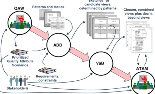
Fig. 2shows how the ADD method fits together with the other SEI architectural design activities. The Quality Attri-bute Workshop (QAW) (Barbacci et al., 2003) helps in understanding the problem by eliciting quality attribute requirements in the form of quality attribute scenarios. The Views and Beyond (VaB) approach (Clements et al., 2002a) documents a software architecture using a number of views based on stakeholders’ needs. The Architecture Tradeoff Analysis Method (ATAM) (Clements et al., 2002b) provides detailed guidance on analyzing the design and getting early feedback on risks. The figure does not show how these methods are used in the context of an orga-nization’s own architecture process (see (Kazman et al., 2004; Nord et al., 2004) for examples of relating ADD to the Rational Unified Processand Agile methods).
1 A shorter version of this work was presented at WICSA (Hofmeister
2.2. Siemens’ 4 views
The Siemens Four-Views (S4V) method (Hofmeister et al., 1999; Soni et al., 1995), developed at Siemens Corpo-rate Research, is based on best architecture practices for industrial systems. The four views (conceptual, execution, module and code architecture view), separate different engi-neering concerns, thus reducing the complexity of the architecture design task.
In the conceptual view, the product’s functionality is mapped to a set of decomposable, interconnected com-ponents and connectors. Comcom-ponents are independently executing peers, as are connectors. The primary engineer-ing concerns in this view are to address how the system fulfills the requirements. The functional requirements are a central concern, including both the current
require-ments and anticipated future enhancerequire-ments. Global properties such as performance and dependability are addressed here as well as in the execution view. The system’s relationship to a product family, the use of COTS, and the use of domain-specific hardware and/or software are all addressed in the conceptual view as well as in the module view.
For the module view, modules are organized into two orthogonal structures: decomposition and layers. The decomposition structure captures how the system is logi-cally decomposed into subsystems and modules. A module can be assigned to a layer, which then constrains its depen-dencies on other modules. The primary concerns of this view are to minimize dependencies between modules, max-imize reuse of modules, and support testing. Another key concern is to minimize the impact of future changes in Fig. 1. Recursively designing the architecture using ADD.
COTS software, the software platform, domain-specific hardware and software, and standards.
The execution architecture view describes the system’s structure in terms of its runtime platform elements (e.g., OS tasks, processes, threads). The task for this view is to assign the system’s functionality to these platform elements, determine how the resulting runtime instances communicate, and how physical resources are allocated to them. Other considerations are the location, migration, and replication of these runtime instances. Runtime prop-erties of the system, such as performance, safety, and replication must be addressed here.
The last view, the code architecture view, is concerned with the organization of the software artifacts. Source com-ponents implement elements in the module view, and deployment components instantiate runtime entities in the execution view. The engineering concerns of this view are to make support product versions and releases, mini-mize effort for product upgrades, minimini-mize build time, and support integration and testing.
These views are developed in the context of a recurring Global Analysis activity (Hofmeister et al., 2005b). For Global Analysis, the architect identifies and analyzes fac-tors, explores the key architectural issues or challenges, then develops design strategies for solving these issues.
The factors that influence the architecture are organized into three categories: organizational, technological, and product factors. The purpose of the categories is to help the architect identify all influencing factors, including not just requirements but also desired system qualities, organi-zational constraints, existing technology, etc. These factors are analyzed in order to determine which factors conflict, what are their relative priorities, how flexible and stable is each factor, what is the impact of a change in the factor, and what are strategies for reducing that impact.
From these factors the key architectural issues or chal-lenges are identified; typically they arise from a set of factors that, taken together, will be difficult to fulfill. Issues can arise when factors conflict, or when certain factors have little flex-ibility, a high degree of changeability, or a global impact on the system. The architect need not necessarily identify and analyze all factors before identifying the key issues. Some-times it is more fruitful to let an issue give rise to a number of factors, or to alternate between these two approaches.
The next step is to propose design strategies to solve the issues, and to apply the design strategies to one or more of the views. Strategies often involve applying software engi-neering principles, heuristics, and architectural patterns or styles to solve the problem. When a strategy is applied to a particular part of a view, we call it a ‘design decision’. During design, the design decisions must be evaluated, particularly for conflicts and unexpected interactions. This evaluation is ongoing. Thus Global Analysis activities are interleaved with view design activities, and the design activ-ities of each view are also interleaved (seeFig. 3).
In contrast to the ongoing evaluation that is part of the design process, periodic architecture evaluation is done in
order to answer a specific question, such as cost prediction, risk assessment, or some specific comparison or tradeoff. This typically involves other stakeholders in addition to the architect. Global Analysis provides inputs to this kind of architecture evaluation, for example: business drivers, quality attributes, architectural approaches, risks, trade-offs, and architectural approaches.
2.3. RUP’s 4 + 1 Views
The Rational Unified Process (RUP) is a software development process developed and commercialized by Rational Software, now IBM (Kruchten, 2003). For RUP ‘‘software architecture encompasses the set of significant decisions about the organization of a software system:
• selection of the structural elements and their interfaces by which a system is composed,
• behavior as specified in collaborations among those elements,
• composition of these structural and behavioral elements into larger subsystem,
• architectural style that guides this organization. Software architecture also involves: usage, functionality, performance, resilience, reuse, comprehensibility, economic and technology constraints and tradeoffs, and aesthetic concerns.’’ RUP defines an architectural design method, using the concept of 4 + 1 views (RUP 4 + 1) (Kruchten, 1995): four views to describe the design: logical view, pro-cess view, implementation view and deployment view, and using a use-case view (+1) to relate the design to the context and goals (seeFig. 4).
In RUP, architectural design is spread over several iterations in an elaboration phase, iteratively populating the 4 views, driven by architecturally significant use cases, non-functional requirements in the supplementary specifi-cation, and risks (see Fig. 5). Each iteration results in an executable architectural prototype, which is used to validate the architectural design.
Architectural design activities in RUP start with the fol-lowing artifacts, which may not be finalized and still evolve
Organizational Factors Technological Factors Product Factors Design and Evaluation Tasks Global Analysis Issue Cards new factors, issues, or strategies Design of other Architecture Views
Architecture View Design
during the architectural design: a vision document, a use-case model (functional requirements) and supplementary specification (non-functional requirements, quality attri-butes). The three main groups of activities are:
(1) Define a Candidate Architecture
This usually starts with a use-case analysis, focusing on the use cases that are deemed architecturally sig-nificant, and with any reference architecture the orga-nization may reuse.
This activities leads to a first candidate architecture that can be prototyped and used to further reason with the architectural design, integrating more ele-ments later on.
(2) Perform Architectural Synthesis
Build an architectural proof-of-concept, and assess its viability, relative to functionality and to non-func-tional requirements.
(3) Refine the Architecture
Identify design elements (classes, processes, etc.) and integrate them in the architectural prototype
Identify design mechanisms (e.g., architectural pat-terns and services), particular those that deal with concurrency, persistency, distribution.
Review the architecture.
And the RUP also provides activities related to the doc-umentation of the architecture in each of the 5 views shown inFig. 4.
More recently (Rozanski and Woods, 2005) have added perspectivesto RUP’s views and viewpoints, to more effec-tively capture certain quality properties, in a way similar to architectural aspects or SEI’s tactics (Bass et al., 2003). 2.4. Business architecture process and organization
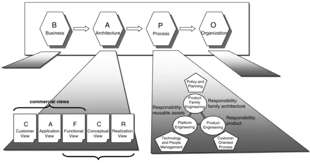
The BAPO/CAFCR approach (America et al., 2003; Muller, 2005; Obbink et al., 2000; van der Linden et al., 2004), developed primarily by Philips Research, aims at developing an architecture (the A in BAPO) for software-intensive systems that fits optimally in the context of busi-ness (B), (development) process (P), and organization (O). Ideally the entities at the right side of the BAPO acronym should be driven by and support the entities at their left (seeFig. 6), even though this does not always work in prac-tice, so that the architecture must fit into a given context of business, process, and organization.
For the architecture, the five CAFCR views are defined: Customer, Application, Functional, Conceptual, and Real-ization. These views bridge the gap between customer needs, wishes, and objectives on the one hand and techno-logical realization on the other hand.
In BAPO/CAFCR, the architect iteratively: (1) fills in information in one of the CAFCR views, possibly in the form of one of the suggested artifacts; (2) analyzes a partic-ular quality attribute across the views to establish a link between the views and with the surrounding business, processes and organization (seeFig. 7). To counteract the tendency towards unfounded abstraction, specific details are often explored by story telling. The reasoning links valuable insights across the different views to each other. The architecture is complete when there is sufficient infor-mation to realize the system and the quality attribute analysis shows no discrepancies.
At a larger scale, the processes described in the BAPO/ CAFCR approach deal with the development of a product family in the context of other processes in a business. 2.5. Architectural separation of concerns
Architectural separation of concerns (ASC) or ARES System of Concepts (Ran, 2000), developed primarily by Nokia, is a conceptual framework based on separation of concerns to manage complexity of architecture design.
Fig. 8illustrates the ASC model of architecture-centered development. Development goals affect architectural deci-sions. Architectural decisions are represented by architec-ture descriptions. Architecarchitec-ture descriptions are used to verify architectural decisions. Architecture description and implementation must be consistent. A validation pro-cess exists to determine consistency of architecture and implementation. Information regarding achievement of
Logical View Implementation View Process View Deployment View Use Case View Programmers Software management Performance Scalability System Integrators End-user, designers Functionality System topology Delivery, installation Communication System Engineering Users/Analysts/Testers Behavior
Logical View Implementation View Process View Deployment View Use Case View Programmers Software management Performance Scalability System Integrators End-user, designers Functionality System topology Delivery, installation Communication System Engineering Users/Analysts/Testers Behavior
Fig. 4. RUP’s 4 + 1 views.
Business Use Cases
System Use Cases Scenarios Classes Objects Sources Processes Processors Low Level Low Level High Level High Level Instance Instance Abstraction Abstraction Use-case view Logical view Deployment view Process view Implementation or code view
Business Use Cases
System Use Cases
System Use Cases ScenariosScenarios Classes
Classes ObjectsObjects
Sources Processes Processors Low Level Low Level High Level High Level Instance Instance Abstraction Abstraction Use-case view Logical view Deployment view Process view Implementation or code view
development goals is obtained once the implementation is available.
Stakeholder goals need to be analyzed and if determined to have an effect on software architecture, the goals need to be refined into architecturally significant requirements (ASR) that state how to measure the achievement of the
goal and indicate how the goal constrains software architecture.
Software goes through a transformation cycle that con-sists of separate segments. During the design or develop-ment segdevelop-ment, the software is source code. During the build segment the software is object files and library
explore
specific details
submethods
and artifacts
framework
integration
via qualities
reasoning
story use case analyse design detailed design analyse design a priori solution know-how market vision safety performance + key drivers + value chain + business models + supplier map + stakeholders and concerns + context diagram + entity relationship models + dynamic models + use case + commercial, logistics decompositions + mapping technical functions and several more+ construction decomposition + functional
decomposition + information model and many more
+ budget + benchmarking + performance analysis + safety analysis and many more
C
ustomerA
pplicationF
unctionalC
onceptualR
ealizationmethod outline
method visualization
throughput processing library diagnostic quality image quality IQ spec pixel depth CPU budget typical case common console memory limit BoM Moore's law purchase price CoO render engine M' S M B U" P' T U U' P profit margin standard workstation memory budget
Fig. 7. Elements of the CAFCR method.
B Business A Architecture P Process O Organization commercial views technical views C Conceptual View R Realization View F Functional View A Application View C Customer View Responsibility: product Responsibility: family architecture Responsibility: reusable assets Policy and Planning Technology and People Management Customer Oriented Process Product Family Engineering Platform Engineering Product Engineering
archives. During the upgrade segment the software consists of executable files. During the start-up segment the soft-ware is system state and groups of executable entities with their dependency structure. During the operation segment software is threads and objects.
Architecturally significant requirements must be grouped so that requirements in different groups may be satisfied independently, while requirements within each group may interact and even conflict. This can be achieved if we group the requirements by the segment of software transformation cycle. Architectural concerns that are related to different segments of the software transformation cycle can be addressed independently, while concerns that are related to the same segment cannot be addressed independently and must be a subject of trade-off decisions.
Fig. 9illustrates the separation of architectural concerns based on different segments of software transformation cycle.
In addition to design of architectural structures for each segment, ASC pays special attention to design of tex-ture. Certain design decisions that are only visible within relatively fine-grained components are nevertheless
extre-mely expensive to revise. Consequently such decisions are architecturally significant even though they are con-cerned with fine-grained elements. This happens when the implementation of the decision cannot be localized, but must be replicated creating recurring uniform micro-structure or texture.
In ASC, the architect analyses design inputs, such as preferred technology platforms, road maps, functional and quality requirements for the product family and the product, and using a palette of techniques, produces and prioritizes ASR (architecturally significant requirements), groups ASR by segments of the software transformation cycle that they address. Implementation (write-time) design addresses the ASR concerned with the write-time segment. Design decisions make implementation technology choices, partition functional requirements between different architectural scopes of product portfolio, product family, or single product, establish portability layers for multiplat-form products, allocate classes of functional requirements to different subsystems, and develop description of the API facilitating work division and outsourcing. Performance (run-time) design deals with run-time ASR addressing concurrency and protection, develops performance models and makes decisions regarding task and process partitions, scheduling policies, resource sharing and allocation. Finally, delivery/installation/upgrade design decisions address the ASR of the corresponding segments. Typical decisions address partitions into separately loadable/exe-cutable units, installation support, configuration data, upgrade/downgrade policies and mechanisms, manage-ment of shared components, external dependencies and compatibility requirements.
3. A general model for software architecture design
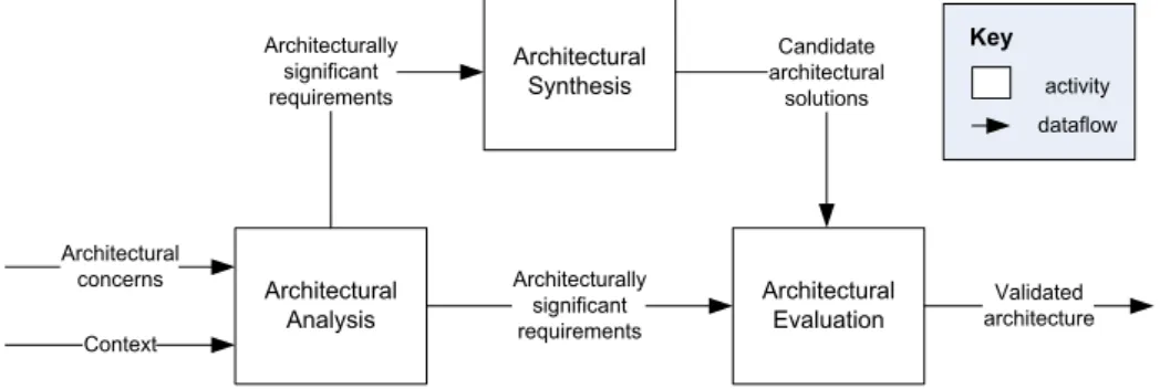
The general model for software architecture design we developed first classifies the kinds of activities performed during design. Architectural analysis articulates architec-turally significant requirements (ASRs) based on the archi-tectural concerns and context. Archiarchi-tectural synthesis results in candidate architectural solutions that address these requirements. Architectural evaluation ensures that the architectural decisions used are the right ones (see
Fig. 10).
Because of the complexity of the design task, these activ-ities are not executed sequentially. Instead they are used repeatedly, at multiple levels of granularity, in no predict-able sequence, until the architecture is complete and vali-dated. Thus the second part of the general model is a characterization of its workflow.
The key requirement of our model was that it be general enough to fit our five architecture design methods, and pro-vide a useful framework for comparing them. One strong influence on the activities in our model was Gero’s Func-tion–Behavior–Structure framework for engineering design (Gero, 1990; Gero and Kannengiesser, 2004), which Kruchten applies to software design inKruchten (2005). Architecture Description Goals Architectural Decisions Implementation affect achieve consistency validation representation verification Evaluation
Fig. 8. A model of architecture-centered software development.
Architecturally Significant Requirements Significant Segments Component Domains Concepts Structure Texture Architecturally Significant Decisions Satisfy
Grouped by Associated with
Organized by
Represent
3.1. Architectural design activities and artifacts
First we describe the main activities of the model, and their related artifacts.
• Architectural concerns: TheIEEE 1471 standard defines architectural concerns as ‘‘those interests which per-tain to the system’s development, its operation or any other aspects that are critical or otherwise important to one or more stakeholders. Concerns include system considerations such as performance, reliability, security, distribution, and evolvability’’ (IEEE, 2000). Most architectural concerns are expressed as requirements on the system, but they can also include mandated design decisions (e.g., use of existing standards). Regula-tory requirements may also introduce architectural concerns.
• Context:According to IEEE 1471, ‘‘a system’s. . . envi-ronment, or context, determines the settingand circum-stances of developmental, operational, political, and other influences upon that system’’ (IEEE, 2000). This includes things like business goals (e.g., buy vs. build), characteristics of the organization (e.g., skills of devel-opers, development tools available), and the state of technology. Note that sometimes the only distinction between a concern and a context is whether it is specif-ically desired for this system (a concern) or is instead a general characteristic or goal of the organization or a stakeholder (context). For example, a business goal of the architecture is a concern, whereas a business goal of the enterprise is context.
• Architecturally significant requirements: An ASR is ‘‘a requirement upon a software system which influences its architecture’’ (Obbink et al., 2002). Not all of the sys-tem’s requirements will be relevant to the architecture. Conversely, not all ASRs will have originally been expressed as requirements: they may arise from other architectural concerns or from the system context. • Architectural analysis: Architectural analysis serves to
define the problems the architecture must solve. This activity examines, filters, and/or reformulates architec-tural concerns and context in order to come up with a set of ASRs.
• Candidate architectural solutions: Candidate architec-tural solutions may present alternative solutions, and/ or may be partial solutions (i.e., fragments of an archi-tecture). They reflect design decisions about the struc-ture of software. The architectural solutions include information about the design rationale, that is, commen-tary on why decisions where made, what decisions were considered and rejected, and traceability of decisions to requirements.
• Architectural synthesis: Architectural synthesis is the core of architecture design. This activity proposes archi-tecture solutions to a set of ASRs, thus it moves from the problem to the solution space.
• Validated architecture: The validated architecture con-sists of those candidate architectural solutions that are consistent with the ASRs. These solutions must also be mutually consistent. Only one of a set of alternative solutions can be present in the validated architecture. The validated architecture, like the candidate architec-tural solutions, includes information about the design rationale.
• Architectural evaluation: Architectural evaluation ensures that the architectural design decisions made are the right ones. The candidate architectural solutions are measured against the ASRs. Although repeated eval-uations of different architectural solutions are expected, the eventual result of architectural evaluation is the validated architecture. Intermediate results would be the validation or invalidation of candidate architectural solutions.
In addition to the above-described artifacts used in the design activities, there are some less explicit inputs that are critical to the design process:
• Design knowledge comes from the architect, from orga-nizational memory, or from the architecture commu-nity. It can take the form of styles, patterns, frameworks, reference architectures, ADLs, product-line technologies, etc.
• Analysis knowledge is needed to define the problem and evaluate the solution. Some work exists in analysis pat-terns (Fowler, 1997) and analytic models associated with Fig. 10. Architectural design activities.
design fragments (Bachmann et al., 2002). Knowledge of the evaluation process itself (e.g., workflow, methods and techniques) (Obbink et al., 2002) can also be an important input.
• Realization knowledge (e.g., technologies, components, project management) is critical. In many cases analysis knowledge is not sufficient to evaluate the architecture. One example is when a partial implementation is needed upon which to do experimentation. In general the design must be evaluated using realization knowledge, in order to ensure that the system can be built.
3.2. Workflow and the concept of backlog
In all five of the architectural methods on which our model is based, the three main activities inFig. 9(architectural anal-ysis, architectural synthesis, and architectural evaluation) do not proceed sequentially, but rather proceed in small leaps and bounds as architects move constantly from one to another, ‘‘growing’’ the architecture progressively over time. This is primarily because it is not possible to analyze, resolve, find solutions and evaluate the architecture for all architec-tural concerns simultaneously: the range and number of interrelated issues is just too overwhelming for the human mind, and moreover the inputs (goals, constraints, etc) are usually ill-defined, initially, and only get discovered or better understood as the architecture starts to emerge.
To drive this apparently haphazard process, architects maintain, implicitly or explicitly, a backlog of smaller needs, issues, problems they need to tackle, as well as ideas they might want to use. The backlog drives the workflow, helping the architects determine what to do next. It is not
an externally visible, persistent artifact; on small projects it may only be a list in the architect’s notebook, while for larger projects it might be an electronic, shared spread-sheet. SeeFig. 11. It is therefore rarely explicitly described in software architectural methods, but we have found it to be actually present in all the methods we have studied, under some name or another, e.g., ‘‘worry list’’ in BAPO, ‘‘issue list’’ in RUP.
The backlog is constantly fed by
(a) selecting some architectural concern and/or ASR from architectural analysis,
(b) negative feedback in the form of issues or problems arising from architectural evaluation, and to a lesser extent,
(c) ideas from the architect’s experience, discussions, readings, etc.
A backlog item can be thought of as a statement of the form:
•‘‘We need to make a decision about X.’’
•or ‘‘We should look at Y in order to address Z.’’ This backlog is constantly prioritized, bringing to the front the items that seem most urgent. The tactics for pri-oritization will vary, mostly based on external forces. These forces include risks to mitigate, upcoming milestones, team pressure to start work on a part of the system, or simply perception of greater difficulty. Very often it is simply the need to relieve pressure from a stakeholder that drives an item to the top of the backlog (the ‘‘squeaky wheel’’ phenomenon).
Once a backlog item (or a small set of backlog items) is picked by the architects, they will proceed to incrementally perform architectural synthesis, making some design deci-sions and integrating them with the existing set of design decisions. Thus the front of the backlog serves to set the objectives for a particular iteration of architectural synthe-sis. Less frequently, backlog items will drive architectural analysis or architectural evaluation. Once resolved in any way (issues resolved, idea explored, requirement satisfied, risk removed, etc.), the item is removed from the backlog, and the architects proceed to the next one. If they encoun-ter some difficulty or some input is missing, the item is returned to the backlog.
Thus the backlog is constantly changing. The cycle of adding to the backlog, reprioritizing, resolving an item, and removing an item is happening at various periods: from a few hours, to a few days, or more.
This backlog is similar to what some Agile methods use for driving projects, in particular Scrum (Schwaber and Beedle, 2002), and this is where the name came from. The backlog guides the architectural design workflow through the three main kinds of activities and provides the objectives for each iteration through the synthesis activ-ity. The kind of tools architects may use for the backlog range from informal lists, to shared spreadsheets, to wiki-based tracking tools such as Trac.
4. Method comparison using the general model
The five architectural methods have been developed independently but there are many commonalities among them.
4.1. Side-by-side comparison
See Tables 1 and 2 for a comparison of activities and artifacts. Putting the methods side by side, helps to identify and understand this commonality as well as the important differences. The rows of the table are based on the activities and artifacts identified in the general model of the previous section.
This comparison has been an iterative process of pro-ducing a common model of design activities and artifacts, seeing how well they relate to the methods, and adjusting the model. Rather than focusing just on the creation of the architectural solution, which is the synthesis activity, the model takes a broad view of architectural design by addressing the interrelated activities of analysis, synthesis, and evaluation.
The steps of ADD follow the sequence of analysis, syn-thesis, and evaluation activities. Subsequent iterations of the activities follow the decomposition of the architecture – the order of which will vary (e.g., depth-first, breadth-first) based on the business context, domain knowledge, or technology.
Global Analysis from S4V plays a large role in analysis and in driving iterations through the activities. Thus it
spans architectural analysis, architectural synthesis, the backlog, and describes how architectural concerns, context, ASRs, and some backlog items should be recorded. The Global Analysis artifacts, design decision table, and tables that record the relationships among views support trace-ability from requirements to the code (at the file and mod-ule level).
4.2. Commonalities
Elements the methods have in common include: • an emphasis on quality requirements and the need to aid
the architect in focusing on the important requirements that impact the architecture during analysis,
• design elements organized into multiple views during synthesis,
• and an iterative fine-grained evaluation activity (per-formed internally after each synthesis result by the architect) as distinct from course-grained evaluation (architectural reviews performed at key stages in the software development lifecycle).
4.2.1. Common theme: dealing with quality requirements Architecture design is often driven by quality or non-functional requirements. Since most operations of the sys-tem involve multiple components, the quality of operations cannot be guaranteed by the design of a single or a small group of components. Therefore architecture is in practice the only means to systematically address quality require-ments. In this respect it is interesting to review how the five methods we discuss in this paper address quality requirements.
In RUP non-functional requirements are captured in supplementary specifications. These specifications are taken into consideration during each of the iterations. However the most important stage is often during the ini-tial iteration when the major architectural structure is established. Non-functional requirements play an impor-tant role at this stage because the selection of the main architectural structure is mainly driven by non-functional requirements. Once an executable prototype becomes avail-able, the capability of the system to address the non-func-tional requirements is assessed and when improvement is necessary further iterations are planned. Perspectives are a recent addition to RUP that help the architect address non-functional requirements (Rozanski and Woods, 2005). Perspectives are views that bring together different elements of design that affect a particular domain of con-cerns. Common domains of concerns are security, data integrity, availability, etc.
ADD uses quality requirements or quality attributes as the driving force for architecture design. ADD relies on a repository of architectural patterns and tactics to address the non-functional requirements. ADD follows a recursive process of hierarchical decomposition of the system. At
Table 1
Comparing methods: activities
Activity ADD S4V RUP 4 + 1 BAPO/CAFCR ASC Architectural
analysis
Choose the module to decompose(Step 1) determines the context and architectural concerns that will be addressed
Global Analysis involves (1) identifying influencing factors; (2) analyzing them to identify their importance to the architecture, flexibility, and changeability; (3) identifying key issues or problems that arise from a set of factors
Build or extract a subset of the use case model and the supplementary specification, as key drivers for architectural design
BAPO analysis identifies those elements of context that are relevant for the architectural fit and determine the scope of the architecture. These elements are already entered into the various artifacts in the CAFCR views. Strategic scenarios can be used to explore multiple possible futures and their
impact on business and architecture
Concept definition, identification and refinement of ASR, partition of ASR by software segments: runtime, development, load, etc. Thus analysis results in a collection of semi separable problems
Choose the architectural drivers
(Step 2a) looks for the combination of functional and quality requirements that ‘‘shape’’ the architecture. The QAW and quality attribute models help elicit and structure the requirements
as needed Architectural
synthesis
Synthesis is iterative as drivers are considered and the candidate architectural solution evolves
The fourth part of Global Analysis, identifying solution strategies, is the beginning of arch. synthesis. Then strategies are instantiated as design decisions that determine the number and type of design elements for one of the software architecture views. Design decisions can be captured in a table
During the elaboration phase, incrementally build an architecture organized along 4 different views; in parallel implement an architectural prototype
Iteratively elaborate the five CAFCR views, adding or refining artifacts suitable for the particular system. No particular order is prescribed. Often a particular quality attribute is ‘‘chased’’ through the different views. Architecture scenarios are defined as responses to the strategic scenarios
Address the ASR, segment by segment in an iterative process, resolving conflicts between the ASR within the same segment and integrating solutions from different segments
This takes place in two parts. In the first part,Choose an architectural pattern that satisfies the architectural drivers
(Steps 2b) architectural tactics and patterns determine the structure of the solution In the second part,Instantiate modules(Step 2c) andDefine interfaces(Step 2d) the decomposition is documented and remaining requirements allocated to the structure Architectural
evaluation
Verify and refine use cases and quality scenarios(Step 2e) verifies the decomposition can collectively satisfy the requirements
and prepares the child modules for their own decomposition, preparing for the next iteration of ADD. A given quality scenario might not be satisfied by the current decomposition. If it is high priority, reconsider the current decomposition. Otherwise record the rationale for why it is not supported (e.g., because of a justified tradeoff between quality attributes)
S4V splits evaluation into global evaluation (done by the architect as the design progresses ) and architecture evaluation, led by a team of external reviewers, and done at major checkpoints (e.g., to validate arch. concepts and after design is complete)
Build an executable prototype architecture to assess whether architectural objectives have been met, and risks retired (elaboration phase)
The CAFCR views are evaluated in the BAPO context to see whether they fit. Furthermore quality attributes are analyzed across the CAFCR views to determine whether the solutions in the technical views satisfy the requirements from the commercial views
Architectural decisions are evaluated with respect to ASR that they address. Typical procedure of evaluation may nclude model-based analysis (LQN, Petri nets, Q nets) simulation, prototyping, and discussion of change/use scenarios
C. Hofmeiste r et al. / The Journal of Systems and Softwar e 8 0 (2007) 106–126
Comparing methods: artifacts
Artifact ADD S4V RUP 4 + 1 BAPO/CAFCR ASC
Architectural concerns
Functional requirements, system quality attribute requirements, design constraints (requirements for which the design decisions are prespecified)
Influencing factors are orga-nizational, technological, and product factors. Product factors, describing required characteristics of the product, are always architectural concerns, so are technological factors (state of technology including standards) that could affect the product
Vision document, Supplementary specification (for non-functional requirements); the Risk List identifies, among others, technical issues: elements that are novel, unknown, or just perceived as challenging
These concerns are expressed in the Customer and Application views. The overriding meta-concern is bridging the gap between customer needs, wishes, and objectives and technological realization
Each product family has lists of typical concerns that need to be addressed by products in the domain. Stakeholders contribute product specific concerns during product conception phase
Context Business quality goals (e.g., time to market, cost and benefit), architecture qualities (e.g., conceptual integrity, buildability), system constraints
Organizational factors (see above) are usually context, not concerns
Business case and Vision document
Business goals and constraints (including the scope of the market to be addressed), process goals and constraints, organizational goals and constraints
Preferred technology platforms
Technology/product road maps
Product family functional and quality requirements System/hardware architecture Implementation constraints Architecturally significant requirements (ASR)
Architectural drivers are the combination of functional, quality attribute, and business requirements that ‘‘shape’’ the archi-tecture or the particular module under consideration. To identify them, locate the quality attribute scenarios that reflect the highest priority business goals relative to the module and have the most impact on the decomposition of the module
Issue cards describe issues or problems that arise from sets of factors that, taken together, pose significant architectural challenges. These issues and their influencing factors are equivalent to the architecturally significant requirements
ASR are identified out of the requirements documents (Vision, use case model, supplementary specification), and the risk list. Some of the ASRs are expressed in the form of scenarios (use case instances) that are allocated as objectives in the upcoming iteration;
this forms a requirements view (+1)
Those elements of the BAPO context that are relevant for the architectural fit and determine the scope of the architecture. Traditional types of requirements are represented in the Customer and Application views, which can be influenced by the architect in order to obtain a better BAPO fit
A specific process is used to identify ASR based on stake-holder concerns, domain and product family specific checklists, and patterns for analysis. ASR are partitioned by segments of software transformation cycle to establish semi-separable solution domains. ASR that are in the same segment are prioritized and analyzed for potential conflicts
Candidate architectural solutions
A collection of views, patterns, architectural tactics, and a decomposition of modules. Each module has a collection of responsibilities, a set of use cases, an interface, quality attribute scenarios, and a collection of constraints. This aids the next iteration of decomposition
Part of the four views (conceptual, module, execution, and code arch. views). These represent design decisions taken in accordance with strategies that solve one or more issues. Issue Cards capture the issues, their influencing factors, and solution strategies. Factors are listed and characterized in Factor Tables
Design decisions are incrementally captured in four views (logical, process, implementation, deployment), supplemented with a use-case view and with complementary texts, and plus an architectural prototype
Consistent and partially complete CAFCR views (Customer, Application, Functional, Conceptual, and Realization), filled with various artifacts
(models, scenarios, interfaces, etc.)
A collection of patterns, frameworks, and reference architectures constitute the source for alternative decisions. An often used practice is to analyze alternatives along with any proposed solutions
(continued on next page)
C. Hofmeiste r et al. / The Journal of Systems and Software 80 (2007) 106–126 117
Table 2 (continued)
Artifact ADD S4V RUP 4 + 1 BAPO/CAFCR ASC
Validated architecture
Architecture describes a system as containers for functionality and interactions among the containers, typically expressed in three views: module decomposition, concurrency, and deployment. The architecture is validated for satisfaction of
requirements/constraints with respect to the decomposition
The description of the four views, the Issue Cards, and the Factor Tables represent the validated architecture
Baseline a complete, executable architectural prototype at the end of the elaboration phase. This prototype is complete enough to be tested, and to validate that major architectural objectives (functional and non-functional, such as performance) have been met, and major technical risks mitigated
Consistent and complete CAFCR views. Consistency means that the artifacts are mutually corresponding and quality attribute analysis shows no discrepancies (for example, all quality requirements from the Application view are satisfied by the Conceptual and Realization views). Completeness means that artifacts have been elaborated in sufficient detail to enable realization
Concepts, structure and texture for each significant segment of software transformation cycle (development/load/runtime)
Backlog Information to be processed in subsequent steps including: requirements to be analyzed, decisions to be merged, patterns to be instantiated, requirements to be verified and refined
Supported in part by Issue Cards, which help the architect identify important issues to address and drive the bigger iterations through the activities. Issue Cards are intended to be permanent artifacts. S4V also recommends the capture of certain inputs to the backlog: Issue Cards can capture strategies (ideas) that do not work
In larger projects, an Issue List is maintained, which contains elements of the backlog. Architectural objectives are allocated to upcoming iterations, and captured in the form of iteration objectives in the iteration plan
Worry List contains: Artifacts to be completed; Quality attributes to be analyzed; Quality requirements to be satisfied; BAPO analysis to be done; BAPO issues to be improved
The initial backlog is a result of the analysis. As the design progresses ASR are partitioned into solvable problems and some are left on the backlog to be addressed later while some are being addressed earlier. Thus entries in the backlog represent finer and finer grained problems or issues The order in which information
is processed will vary, for example, the order of the decomposition varies based on business context, domain knowledge, and technology risk; the determination of drivers is not always a top down process, it might depend on a detailed investigation to understand the ramification of particular requirements and constraints
Design knowledge comes from the architect (or organizational memory or community best practice) and is recorded as an influencing factor. A large amount of general architectural knowledge is documented in the Gaudı` websiteMuller (2005) C. Hofmeiste r et al. / The Journal of Systems and Softwar e 8 0 (2007) 106–126
each stage, depending on the desired quality attributes, a suitable architectural pattern is selected and the system is decomposed according to the pattern. ADD uses prioritiza-tion of quality attributes when architectural patterns can-not support all desired quality attributes at the same time. The ATAM architecture evaluation method comple-ments ADD design and analysis, and is used to analyze how well design choices achieve the trade-off between all desired quality attributes.
In S4V design decisions that affect quality requirements might be reflected in multiple views. Both the conceptual and the execution view may reflect some decisions that affect dependability and performance. Each of the four views has associated quality concerns that may or may not be explicitly designated as quality attributes but are important for most systems. Code architecture view is used to minimize build time, facilitate product upgrades, etc. Module view is used to achieve reuse, and execution archi-tecture view serves to address performance, reliability and other operational concerns. Global analysis is the process in which non-functional requirements are analyzed and strategies to address them are selected. S4V used categori-zation and prioriticategori-zation of requirements and applies this to make sequence design process and to find proper trade-off when conflicts arise.
In BAPO/CAFCR, quality aspects do not belong to a particular view. Rather they form the cross-cutting con-cerns that glue the views together and enable reasoning across the views. Typically, a quality concern arises from the Customer or Application View, where it becomes clear that the system should fulfill a certain customer need or support a particular usage. In the Functional View it is formulated as a specific system quality requirement. The Conceptual and Realization Views should then make sure that this requirement is met, by a combination of applying suitable mechanisms and using suitable technology. Espe-cially for challenging quality concerns, this process may require a significant number of iterations across the views. ASC does not separate quality requirements from other ASR. In fact ASC expects all quality requirements to be defined by specific scenarios where the corresponding qual-ity requirement plays an important role. This is quite sim-ilar to the way functional requirements are defined. ASC relies on segmentation of ASR to make sure that decisions affecting a particular architectural structure can be ana-lyzed independently with respect to the corresponding quality ASR. Within the same segment ASR are prioritized to resolve conflicts and to arrive at optimal trade off choices. Specific choices in the design of each architectural structure are guided by a domain specific collection of architectural patterns which are known for specific quali-ties. Texture design in ASC plays a very important role in addressing a broad range of quality requirements that are orthogonal to the main decomposition pattern of the architectural structure. For example to address quality requirements related to security, flow-control, overload control, fault detection and handling all the components
in the system must observe consistent behavior. However specifics of this behavior are not visible in the common architectural views and may have no impact on the design of architectural structures. Such design decisions are cap-tured by ASC in texture design.
4.2.2. Common theme: multiple views
Table 3summarizes the use of multiple views in the var-ious methods. The primary motivation for multiple views is separation of concerns: to group together closely related concerns, and to have looser coupling between concerns of different views.
Most of the views used in the methods can be catego-rized as structural views, meaning they describe architec-tural structure of the system. These are summarized in the first nine rows of the table. The structural views both guide the architectural synthesis activity and furnish the main documentation of this activity.
S4V and RUP 4 + 1 prescribe specific views. Although they use different names for the views, their views cover similar structures for decomposition and dependencies, instantiation and synchronization, resource usage and organization of development artifacts. They differ in sup-port for inheritance and dataflow.
The other methods are less prescriptive and instead indi-cate indi-categories or typical views. ADD produces the first articulation of the architecture typically using module decomposition and dependencies, concurrency and deploy-ment. Other views can be added: their inclusion and the amount of detail is driven by what is needed to satisfy the architecturally significant requirements. The views for the other two methods are tied to specific concerns. ASC organizes views according to segments that are tied to the software transformation cycle: design/development, build, upgrade, start-up, operation. In BAPO/CAFCR, concerns flow from the customer needs and wishes represented in the commercial views within the context of the business, pro-cess, and organization.
Two methods, RUP 4 + 1 and BAPO/CAFCR have one or more additional views that do not describe architectural structure but instead focus on goals or requirements of the system, and these play a role mainly during the architec-tural analysis activity. Note that ADD, S4V, and ASC also analyze these concerns, but rather than using views they rely on other methods within the software development process to elicit this information. BAPO/CAFCR has the broadest set of views, which are intended to be successive models along a path from requirements to realization.
Finally, in addition to structural views, ASC has the notion of ‘‘texture,’’ a replicated microstructure that applies to most components and crosscuts the structural views.
4.3. Variations
There are also important variations between the methods:
The use of multiple views
ADD S4V RUP4 + 1 BAPO/CAFCR ASC
Structural views The nature of the project determines the views. Typical views are module decomposition, concurrency, and deployment
Four views are used: conceptual, module, execution, and code architecture views
Four views are used: logical, process, implementation, and deployment views
Structural information is mainly in the Conceptual View. Its representation is not fixed by the method, but suggestions are provided
Each segment typically calls for the use of one or more structural views
Development time: structure exhibited in the source artifacts
Decomposition (e.g., of subsystems, modules, classes)
Module decomposition Module Arch. View Logical View Conceptual View: System decomposition and component models
Functionality clusters, view of the module structure
Dependencies (e.g., among modules, interfaces, classes; constrained by layers)
Often part of module decomposition
Module Arch. View Logical View Conceptual View: System decomposition and component models Functionality layers, Portability layers, Inheritance (e.g., of classes) Could be covered by an additional view
Not covered. (Modules are not usually individual classes.)
Logical View Conceptual View: Information models Could be covered by an additional view Runtime: structure exhibited at runtime Instantiation (e.g., components, processes, tasks, objects) Could be covered by an additional view Conceptual Arch. View Execution Arch. View
Process View Conceptual View: Collaborations
Views used in Operation segment
Synchronization (e.g., control flow, threads and their synchronization)
Concurrency ConceptualArch. View Execution Arch. View
Process View Conceptual View: Collaborations
Views used in Operation segment
Dataflow (e.g., how data logically flows through system)
Could be covered by an additional view
Conceptual Arch. View Not covered Conceptual View: Collaborations Could be covered by an additional view Resource usage (e.g., mapping to processes, shared libraries, or other OS resources; mapping to hardware)
Deployment Execution Arch. View Deployment View Conceptual View and Realization View
Views used in Start-up segment Organization of and relationships among permanent and temporary artifacts (e.g., of source, intermediate, executable files) Could be covered by an additional view
Code Arch. View Implementation View Conceptual View: Variation Models
Views used in Build segment, and in Delivery/installation/ upgrade segment
Non-structural views None: results of analysis activity are not captured in a view
None: results of analysis activity are not captured in a view
The +1 (requirements) view is used primarily during analysis. It focuses mainly on functional requirements. It crosscuts the four structural views
The Customer and Application Views describe goals, and the Functional View focuses on functional requirements. These are used primarily during analysis. The Realization View covers technology choices
None: results of analysis activity are not captured in a view C. Hofmeiste r et al. / The Journal of Systems and Softwar e 8 0 (2007) 106–126
• Intent – ADD was developed as a design approach based on making a series of design decisions (aided by the application of architectural tactics). Other view-based approaches were initially centered on design arti-facts, with their dependencies suggesting a sequencing of activities. 4 + 1 embedded in RUP provides full process support. BAPO/CAFCR has been especially developed to support the development of product families. • Emphasis – RUP puts a strong emphasis on
incremen-tally building an evolutionary prototype, forcing the designers to a more experimental style of architectural design. BAPO/CAFCR puts a strong emphasis on the scoping of the architecture and once the scope of the architecture using a BAPO analysis has been established, the focus is on ensuring the consistency and the com-pleteness of the CAFCR views. ADD puts its emphasis on constructing the architecture by applying architec-tural tactics (design options for the architect that are influential in the control of a quality attribute response). • Driving forces – ADD is quality attribute scenario focused; experience suggests that a handful of these shape the architecture and all other requirements are then mapped to this structure. This fact is also recog-nized in ASC, which ties architecture design to architec-turally significant requirements. ASR are broader than quality attributes and may include key functional requirements. RUP is mostly driven by risk mitigation. • Architectural Scope – ASC recognizes a hierarchy of architectural scopes like product portfolio, product fam-ily, a single product, and a product release. Each archi-tecture design project uses the enclosing scope as the context of the design.
• Process Scope – ADD provides a step for choosing the architectural drivers but its scope is such that it depends on more analysis types of activities from other methods, such as global analysis from S4V. However, S4V does not recommend or advocate specific evaluation tech-niques. Thus ADD and S4V complement each other in these respects.
5. A template for analyzing software architecture design methods
One other outcome of this work is the proposal of a kind of grid, or template, based onFig. 10andTables 1 and 2, to analyze other proposed software architecture design methods, or even to drive the development of new architec-ture design methods; seeTable 4.
To illustrate the use of this grid, we have applied it to the architectural method proposed by Garland and Anthony (2002), which we will denote here as G&A; see Table 5. Numbers in this table indicate page in the book. A more complete table could also be created for this method, con-taining the kind of detail given for the other methods in
Tables 1–3.
Using our grid to analyze this method, we can rapidly identify the following points:
1. There is a strong focus on viewpoints and views, and the description of these views using UML to document the architecture; this occupies about half of the book. 2. Many of the activities and techniques are either sketchy
(chapter 11) or refer to other sources. Table 4
A grid to analyze a software architecture design method
Generic artifacts Artifacts in X Activities in X Techniques and tools in X Has the method X
provision for the following artifacts? How are they named and represented?
Is the method X providing activities to produce these artifacts? How are these activities named and documented?
What specific tools and technique is associated with the method X?
Architectural analysis – Context
– Requirements, and – Architecturally significant
requirements (ASR) Architectural synthesis Candidate architectural solutions
– Architectural
design (e.g., views, perspectives) – or Prototypes
– Rationale Architectural evaluation – Quality attributes
– Architectural assessment Overall process driver – Backlog
Other Other key artifacts
of the method X, not matching the
generic ones
Other key activities of the method, not fitting in the boxes above.
3. Building a skeleton or architectural prototype is men-tioned as a possibility.
4. There seems to be no concept of Architectural Signifi-cant Requirements (except for a couple of mentions to ‘‘key requirements’’ and ‘‘key use cases’’ with no expla-nation how they are identified).
5. There is no mention of design rationale (except for some tracing between elements in views, and a mention of requirements tracing p. 49).
6. Architecture evaluation is only mention briefly, and no technique described, nor any artifact.
7. Beyond emphasizing iterative development in chapter 3, there is no indication of any driver for architectural activities.
8. There is very few explicit links to quality attributes. Such an analysis would lead to the rapid identification of element from other techniques that could come to comple-ment some of its deficiencies. For example it would be nicely complemented by the use of SEI’s techniques, such QAW (Barbacci et al., 2003) or ATAM (Kazman et al., 1994; Clements et al., 2002b) , or a better linkage to quality using the ASC approach (see Section2.5), or ADD (see Section2.1). Applying the grid to other methods is often impeded by the lack of detailed material on the proposed methods, associated maybe to their lack of maturity and/or limited use in industry. For example, trying to apply our grid to VTT’s QAD or QADA approach (Matinlassi et al., 2002a,b), we found that views are well-articulated and jus-tified, but there are very little description of the activities that take place. Similarly for methods associated with Model-Driven Architecture (Selic, 2004; Fowler, 2005),
which are not sufficiently mature and well-described to be analyzed by our approach.
6. Related work
We have found four main approaches to comparing design methods. Some researchers compare the methods by comparing their results or artifacts. Others compare the activities done when following the methods. Each of these approaches breaks down further into comparisons based on applying the methods to a particular example application, or comparing the methods by classifying the artifacts or activities.
The first group compares the artifacts for an example application. Bahill et al. (1998) first provide a ‘‘bench-mark’’ application to be used for comparing design meth-ods. Then they provide a qualitative analysis of the results of applying eleven design methods to the bench-mark application.Sharble and Cohen (1993)use complex-ity metrics to compare the class diagrams that result from applying two different OO development methods on a brewery application.
The next group also compares artifacts, but by classify-ing them accordclassify-ing to what they can model. Wieringa (1998)does this for a number of structured and OO speci-fication methods.Hong et al. (1993)do this as part of their comparison of six OO analysis and design methods, so does
Fowler (1993).
The third kind of comparison examines the activities undertaken when designing particular applications. Kim and Lerch (1992)measure the cognitive activities of design-ers when using an OO design method vdesign-ersus a functional Table 5
Analysis of theGarland and Anthony (2002)method (G&A)
Generic artifacts Artifacts in G&A Activities in G&A Techniques and tools in G&A Architectural analysis – Context – Requirements, and – Architecturally significant requirements (ASR)
– contextual and analysis viewpoint (p. 13, 87–108) – ?? – Analysis process, similar to OOSE OOSEJacobson et al. (1992) Architectural synthesis
Candidate architectural solutions + Architectural design
(e.g., views, perspectives) + Prototypes
+ Rationale
– Logical design viewpoints (decomposes in component viewpoint, logical data,
layered subsystem,. . .) (p. 87–174) – Environment/physical viewpoint (deployment, process, physical data) (p.177–200) – skeleton system (p. 205) & prototyping (p. 206)
Small activities scattered in the book,
to populate the views, but not named explicitly.
– partitioning strategies (208–213) – changeability and dependency management (213–216) – UML (p. 69–86) – use of ADL (p. 208) – pattern (p. 216–218) Architectural evaluation – Quality attributes – Architectural assessment – ?? – ?? – Commonality and variability analysis (p. 202) – Architecture evaluation (p. 208) Overall process driver – Backlog – ?? – ??