A Framework for Stateful Inspection
- Applied to TCP and Linux Netfilter
Group D505c
Mikkel Refsgaard Bech Torben Vinther Schmidt
Carsten Stiborg
Department of Computer Science
Aalborg University
Aalborg University
Department of Computer Science
Title: A Framework for Stateful Inspection - Applied to TCP and Linux Netfilter
Project period: September 4th, 2001 - Jan 14th, 2002 Project group: D505c
Group members: Mikkel Refsgaard Bech Torben Vinther Schmidt Carsten Stiborg Supervisors: Mikkel Christiansen Emmanuel Fleury Numbers of Copies: 7 Number of Pages: 66 Synopsis
This project examines the concept of stateful inspection and how it is applied in firewalls. First a framework con-taining a modeling language for networking protocols is derived. This is used to model the Transmission Control Protocol (TCP) which is used as case study. Then the concept of stateful inspection is applied to TCP in order to get a model for use in firewalls. Afterwards, the Linux Netfilter code is reverse engineered in order to create a model for comparison with the model for stateful inspec-tion on TCP. The result of the comparison is a proposal for improved stateful inspection within Linux Netfilter. The report concludes that the framework was applicable in improving stateful inspection within Linux Netfilter.
This project was prepared on the DAT5-semester at the Department of Computer Science at Aal-borg University, Distributed Systems and Semantics division, in the fall of 2001 and January 2002. It has been made with help from the open source community and their resources (homepages, FAQs, HOWTOs, and mailing lists).
The goal of the project was to provide a framework for improving implementations of stateful in-spection firewalls. We propose a framework for modeling network protocols and use this to model stateful inspection on TCP. We have reverse engineered an implementation of stateful inspection in order to model it. Based on a comparison of the models we propose improvements for the implementation.
Our approach is not deeply theoretical but emphasizes application of our findings to practical use. Throughout the report, there are examples, tables, and figures. These are all enumerated within each chapter, e.g. Figure 3-1 means the first figure in chapter 3.
In the appendix A and B are important parts of the source code of the implementation.
Aalborg, January 14th, 2002
Mikkel Refsgaard Bech Torben Vinther Schmidt
1 Introduction 1
1.1 Firewalls . . . 1
1.1.1 The Generic Firewall . . . 1
1.1.2 Open Systems Interconnection . . . 2
1.2 Packet, Stateful Inspection, and Application Firewalls . . . 3
1.2.1 Packet Firewalls . . . 3
1.2.2 Stateful Inspection Firewalls . . . 4
1.2.3 Application Layer Firewalls . . . 5
1.3 Alignment and comparison . . . 6
1.3.1 Comparison of Firewalls . . . 6
1.3.2 Improving Stateful Inspection Firewalls . . . 8
1.4 Project Objective . . . 8
1.5 The Structure of the Report . . . 9
2 Framework 11 2.1 The Formalism . . . 11
2.2 Graphical representation . . . 13
3 The Transmission Control Protocol 15 3.1 The Protocol . . . 15 3.1.1 The TCP Header . . . 15 3.2 Connection Phases . . . 17 3.2.1 Connection Establishment . . . 17 3.2.2 Established Connection . . . 18 3.2.3 Connection Termination . . . 20
3.3 TCA for a TCP Connection . . . 20
4 Stateful Inspection on TCP 25
4.1 The Man In The Middle . . . 25
4.2 Stateful Inspection on TCP . . . 25
4.2.1 Handshakes . . . 26
4.2.2 Window Size and Sequence Numbers . . . 27
4.2.3 Resetting the Connection . . . 30
4.3 The Stateful Inspection Model . . . 30
4.4 Stateful Inspection Issues . . . 31
4.4.1 Model Completeness . . . 31
4.4.2 Passive or Active . . . 31
4.4.3 Other Protocols . . . 34
4.5 Summary . . . 35
5 The Netfilter Implementation 37 5.1 Linux and Netfilter . . . 37
5.1.1 Netfilter Architecture . . . 37
5.1.2 Netfilter Modules . . . 37
5.2 Implementation of TCP State Tracking . . . 39
5.2.1 Handshake Check . . . 39
5.2.2 Transitions . . . 40
5.3 The State Table . . . 41
5.3.1 The State Entry . . . 43
5.4 Summary . . . 45
6 Applying the Stateful Inspection TCP Model to Netfilter 49 6.1 Similarities . . . 49 6.2 Differences . . . 50 6.3 Improvement Proposals . . . 50 7 Conclusion 53 A Excerpt of ip_conntrack_core.c 55 B ip_conntrack_proto_tcp.c 61
1-1 A typical proxy relaying FTP requests for a HTTP browser. . . 5
1-2 The SOCKS proxy relays the client requests through the SOCKS layer. . . 6
2-1 A TCA containing three states. . . 14
3-1 The header format for TCP. . . 15
3-2 Connection establishment for the client. . . 18
3-3 Connection establishment for the server. . . 19
3-4 Active connection termination, shown as a TCA. . . 21
3-5 Passive connection termination, shown as a TCA. . . 21
3-6 This TCA shows how a TCP connection acts as specified. . . 22
3-7 The retransmission workaround. . . 23
4-1 The ACK is blocked even though it is legal, because the state has changed back. . 27
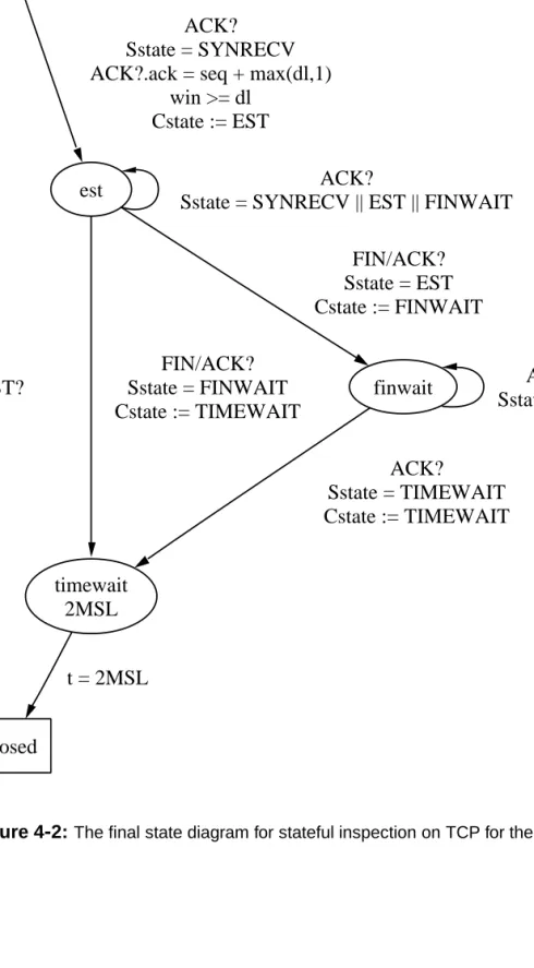
4-2 The final state diagram for stateful inspection on TCP for the client. . . 32
4-3 The final state diagram for stateful inspection on TCP for the server. . . 33
5-1 The Netfilter architecture. . . 38
5-2 Schematic representation of the minimal Netfilter struct used at each state entry. . 44
5-3 State changes, client side. . . 46
1-1 The TCP/IP model aligned to the OSI model. . . 3 1-2 Where firewalls operate in accordance to the ISO and TCP/IP models. . . 7 5-1 Timeout periods for TCP as defined by ip_conntrack. . . 43
CHAPTER1
During the last 10 years the use of computer networks has exploded. A network is a number of computers that are connected by some medium that allows them to communicate. Networks are established internally in almost all companies and professional organizations. Some networks provide connectivity through them to other networks in order to share resources. This creates a larger network, which is called the Internet.
It may not be the case that all the resources that a network provide is willing to share them with others. Some resources are meant only for our private network. Each of the computers in a network has an address so it can be contacted. This also implies that if someone want to access this computer from any other network, that person is able to do that. This also means that this person could attack this computer and gain access to confidential information.
That someone could access confidential information is of course unwanted. Therefore policies are created for what is allowed on a network. This policy can be expressed in many ways including, but not limited to, something as simple as piece of written paper or a list in the network administrators head.
However, since the policy can be ignored by someone on a different network, a method for enforc-ing these policies are needed. A way to enforce the policies against other networks is by usenforc-ing a firewall.
1.1 Firewalls
In this section we will define the generic firewall and introduce our perspective of different types of firewalls. In order to understand in which environment firewalls works, they will be aligned to the Open Systems Interconnection (OSI) reference model. The general types of firewalls that we will introduce are packet firewalls, stateful inspection firewalls and application firewalls. First, the generic firewall will be defined.
1.1.1 The Generi Firewall
As mentioned earlier, networks are composed of connected computers. Networks are used to send messages from one machine to another. The passing of messages between computers is called communication. We define that the private network is a network over which we have administra-tive control and want to protect from public networks, which is a network that we can not control, e.g. the Internet.
The firewall is a machine which is on the border between networks and inspects communication that enters or leaves the network for messages that we do not allow in our policy. To define what
1.1 Firewalls Introduction
unwanted communication is, we compose a set of rules which are derived from the policies. The firewall applies an interpretation of the rules to the messages and thereby classifying the messages according to the rules, i.e. decides what to do with the message. It could accept it through to the private network, remove the message, or reject the message (telling the sender that it does not allow the message into the network).
In short a firewall is a computer which determines which messages are allowed onto a given network. When computers communicate they do it using a network protocol. A protocol is a set of formal rules for how communication between computers must proceed. These protocols exist on different layers.
1.1.2 Open Systems Interonnetion
In order to find out what layers protocols and firewalls work on we look at the Open Systems Interconnection (OSI) reference model. This is a standard for network protocols on different layers proposed by the International Standards Organization (ISO) [Tan96]. Each layer has a well-defined behavior and does not overlap. Following are the different layers, starting from the bottom layer ascending to the top.
Physical The physical layer is the actual hardware, it is this layer that handles the actual commu-nication, on this layer the data type considered are bits.
Data Link The data link layer handles the errors originating in the physical layer, thereby assur-ing that the data sent and received are alike. This layer works with frames.
Network The network layer is the first layer to handle end-to-end communication, the previous layers only consider the next step in the route. This layer considers the data sent and received as messages or rather packets.
Transport The transport layer takes care of sending the data received from the session layer, splitting it up into smaller pieces if needed and concatenating the data it receives from the network layer, if it has been split. The main goal of the transport layer is to separate the network layer from the session layer, the network layer changing with the hardware it is built upon, and the session layer only being dependent on the operating system it is implemented in. [RAD01]
Session The session layer enlarge the service provided by the transport layer, while the trans-port layer only handles data going in one direction, the session layer applies the possibility of traffic going in both directions. The session layer also implements the concept of check-points in the received stream. If either the sender or the receiver brakes down, the checkpoint is used to restart the transmission from its position.
Presentation The presentation layer takes care of presenting datatypes like integers, strings, char-acters, floats, etc. correct on different types of machines.
Application The application layer contains many different protocols, like email, directory lookup, remote job execution, etc.
Introduction 1.2 Packet, Stateful Inspection, and Application Firewalls
When an application wants to communicate to an application on another machine it sends the data to the underlying layer. This layer wraps the data, giving it a header and possibly a trailer. These contain information which is appropriate for that layer, e.g. the transport layer adds information about how many pieces that data has been split into. The combination of header, data, and trailer is then send to the underlying layer which then again adds a header and possible a trailer, and so on, until the everything is send over the network to the other machine. The data then traverses the layers in the reverse order, unwrapping on each layer until the data is delivered to the appropriate application. Because the OSI model is build in layers, an implementation on one layer can be replaced by another implementation without affecting the other layers.
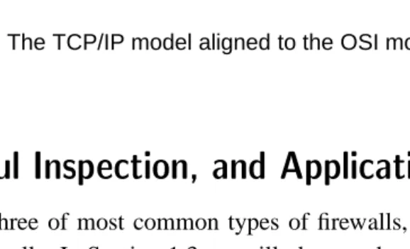
A more thorough description of the different layers can be found in [Tan96]. The OSI model is very general and this may be hindering when designing network protocols. Therefore, designers tend to cut corners. This is the case with the most commonly used protocols on the Internet. These are the Transmission Control Protocol (TCP) and Internet Protocol (IP) [TMW97]. These are almost always used together and therefore also known as TCP/IP. In Table 1-1 the TCP/IP model is aligned to the OSI model. As shown, the physical and data link layer is combined into one, since the software needed to control the physical layer always follows the network interface. The presentation and the session layer from the OSI model does not exist in TCP/IP. Some session procedures are, however, present in the TCP protocol, e.g. two-way connections. Also presentation is commonly handled on the application layer to the extend needed for that protocol.
Layer OSI TCP/IP
7 Application Application 6 Presentation
5 Session
4 Transport Transport (TCP) 3 Network Internet (IP) 2 Data Link Host-to-network 1 Physical
Table 1-1:The TCP/IP model aligned to the OSI model.
1.2 Paket, Stateful Inspetion, and Appliation Firewalls
We will take a closer look at three of most common types of firewalls, namely packet, stateful inspection, and application firewalls. In Section 1.3 we will place each of these types of firewalls in alignment to the models in Table 1-1.
1.2.1 Paket Firewalls
These are firewalls that operate on the Internet and Transport layer of the TCP/IP model and fo-cuses on packets. This means that decisions are made based on single packets, i.e. not considering the context.
1.2 Packet, Stateful Inspection, and Application Firewalls Introduction
A packet firewall examines whether to let a packet continue or to discard it by testing on a pre-defined set of rules. A rule consist of information that must be present in the received packets header. That information could be the address from which the packet was sent, or what protocol is used, e.g. TCP. Rules can be created on combined information e.g. into a rule stating that the packet must be a TCP packet and it must be sent from a certain address, in order to be accepted. The sequence in which the rules are applied is of importance since the packet firewall compares each packet with one rule at a time. The rules are exemplified in Example 1.
Example 1
Allow protocol TCP source IP = 192.*.*.*
Deny ALL
This says that TCP packets with source IP starting with the number 192 is allowed. If the packet does not apply to this rule, the next rule denies it.
1.2.2 Stateful Inspetion Firewalls
Stateful inspection firewalls operate on the network, transport, and application layer. They focus on protocols rather than single packets or data.
We have found no definition of what stateful inspection is and firewalls that are claimed to be stateful differ a lot in functionality. In order to clarify what we mean by stateful inspection we will define it.
In stateful inspection the protocol and the states of the protocol are known. Likewise, all messages of a communication is known and the states of each of the communications are known. On the basis of this we define it as:
Determining whether the state of a communication conforms with the state of the corresponding protocol.
This implies that the events dictated in a protocol are known and the sequence of these events are also known. We say that when a certain event has happened the protocol is in a certain state. Likewise, communication have the same events and therefore states. However, it can at some point differ from the protocol and when this happens it is known.
While stateful inspection is only to determine the state of communication, stateful inspection firewalling is the act of filtering on the basis of the state of communication. In the rest of the report when referenced to stateful inspection, the act of filtering using stateful inspection is meant. What is done is ensuring that a communication behaves the way it should. If we discover that a communication changes state, we check if it is a legal state change and if not, react by discarding or rejecting the message, otherwise we allow it to pass and note that the state has changed for that connection.
In addition to this, rule filtering can be done, i.e. determining by rules which kind of message is allowed based on the state of communication. This could be a rule which says that the com-munication is not allowed to change to certain state, e.g. a rule that says that a certain type of communication is not allowed to be initiated.
Introduction 1.2 Packet, Stateful Inspection, and Application Firewalls
1.2.3 Appliation Layer Firewalls
Application layer firewalls operate on the application layer of the TCP/IP model. These firewalls have very different characteristics, but common is that they focus on application layer protocols rather than on the packets. We will briefly go through the most common.
Proxies
A proxy firewall is an application that relays packets for a client. The main idea is to deny all, except that which is allowed to pass through the firewall. What is allowed through the firewall is determined by rules for who is allowed to use it and what the firewall supports.
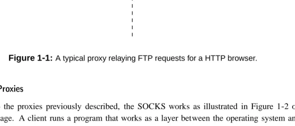
Proxies are used for various reasons in addition to firewalling, e.g. a proxy can be used to mask the real IP-address of the clients using it. Also, it can be used to translate messages between protocols, e.g. letting a client use a Hyper Text Transfer Protocol (HTTP) browser to browse a File Transfer Protocol (FTP) site, communicating through HTTP to the proxy server, while the proxy server communicates with the FTP server through FTP. This is illustrated in Figure 1-1.
HTTP Proxy FTP Server
HTTP answer
HTTP request FTP request
FTP answer
HTTP Browser
Private Network
Public Network
Figure 1-1:A typical proxy relaying FTP requests for a HTTP browser.
SOCKS Proxies
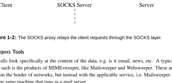
Similar to the proxies previously described, the SOCKS works as illustrated in Figure 1-2 on the next page. A client runs a program that works as a layer between the operating system and the application when the application accesses the network. Basically, it replaces the “send” and “recv” primitives used with sockets, which makes it operating system independent. The SOCKS client then connects to the SOCKS server which then in return relays the communication to the application server which the client applications is trying to connect to. The SOCKS client works like a wrapper for network communication and the SOCKS server then works as a gateway for the application, denying all other communication. Some applications have their own SOCKS client and therefore have no need for an external one. The SOCKS proxy technology has been developed by NEC [NEC01] and is free for non-commercial use.
1.3 Alignment and comparison Introduction
SOCKS Client Application Client
SOCKS Server Application Server
Client
SOCKS Server
Server
OS OS OS
Public Network
Private Network
Figure 1-2:The SOCKS proxy relays the client requests through the SOCKS layer.
MIMEsweepers Tools
Some firewalls look specifically at the content of the data, e.g. is it email, news, etc. A typical example of such is the products of MIMEsweeper, like Mailsweeper and Websweeper. These are not placed on the border of networks, but instead with the applicable service, i.e. Mailsweeper is placed on the same machine that runs as a mail server.
MIMEsweeper protects by providing a plug-in interface for handling different application proto-cols. This is e.g. done by providing an anti-virus tool for the Mailsweeper interface. Mailsweeper then uses this anti-virus tool with each mail going to or from the mail server.
The MIMEsweeper tools contain a very large interface for policy declaration, this is needed since data is separated into many distinct types on this layer. When defining the policies one should consider each possible data type that can be transferred through the network, e.g. movies, pictures, and documents which can be a quite demanding task. [MIM01]
1.3 Alignment and omparison
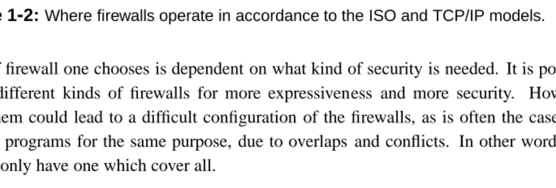
In Table 1-2 on the facing page each of the firewalls are placed corresponding to the layer they operate on using the layers from Table 1-1 on page 3.
We can see that stateful inspection firewalls include filtering on the application, transport, and network layers. All that is really needed for stateful inspection firewalls is a protocol for which states exists. This means that the concept of stateful inspection could in theory be used on any layer of the OSI model.
1.3.1 Comparison of Firewalls
When considering which type of firewall to use there are different points which speaks for each of them and we will discuss them here.
Introduction 1.3 Alignment and comparison
Layer OSI TCP/IP Firewalls
7 Application Application Proxy, SOCKS proxy, MIMEsweeper Stateful inspection firewall 6 Presentation
5 Session
4 Transport Transport Stateful inspection firewall 3 Network Internet Packet filter firewall 2 Data Link Host-to-network
1 Physical
Table 1-2:Where firewalls operate in accordance to the ISO and TCP/IP models. What kind of firewall one chooses is dependent on what kind of security is needed. It is possible to combine different kinds of firewalls for more expressiveness and more security. However, combining them could lead to a difficult configuration of the firewalls, as is often the case with using several programs for the same purpose, due to overlaps and conflicts. In other words it is preferable to only have one which cover all.
Where, being kernel space or user space, the different firewall operates is essential for the effi-ciency of the filter. In kernel space interaction with the Transport and Network layer is done much faster and thus allowing for a higher load of communication. However, kernel space is very lim-ited and very little can be stored. Filters that work in user space access the network through kernel space and thus are slower than filters in kernel space because they have to go through this layer. However, user space have much more storage space.
As we want the firewall to be efficient we of course tend towards those that run in kernel space. Packet filters does not need to store anything and can therefore easily run in kernel space. Stateful inspection firewalls need to store information about the communication but not the content of messages and can also run in kernel space. Application firewalls need to store the content of messages, which can be quite a lot and must therefore run in user space.
We also want a firewall to be able to express our policies fully and we therefore tend towards those which have a lot of expressiveness. When it comes to expressiveness, packet filters are limited because they can not express relations in communication. What is meant by this is that if we allow communication from a computer inside the network to a computer outside the network, we also allow for that computer to communicate in the other direction. We can not express that we only allow replies and not requests from that computer. Stateful inspection surpasses this by considering the communication instead of packets. Stateful inspection firewalls can then express that only if the computer from within the network starts to communicate to a computer outside, the computer outside is allowed to reply. When considering application firewalls we have even more information to base our rules on. These are able to express that a certain content is not allowed within a message.
Where we want both expressiveness and efficiency of a firewall, stateful inspection offers the best tradeoff between these. Along with this and its ability to operate on all layers makes it a desirable type of firewall.
1.4 Project Objective Introduction
1.3.2 Improving Stateful Inspetion Firewalls
As mentioned earlier the understanding of stateful inspection in existing firewalls vary a lot. We therefore recognize a need for some kind of framework for how a stateful inspection firewall should be implemented. This should be based on the definition of what stateful inspection is, which was given earlier.
A way to prove by example that this framework is applicable to firewalls, a case study could be done. This should both be in terms of a protocol and a current implementation of stateful inspec-tion firewall. The purpose is for the framework to pinpoint problems within the implementainspec-tion and/or vice versa.
In order to apply the framework, a model of the protocol from a firewall’s point of view has to be made in addition to a model of the implementation. Comparing these will show differences and similarities. On the basis of this comparison, an improvement proposals for stateful inspection within the implementation must be made.
1.4 Projet Objetive
When networks are joined together, security becomes an issue. Network administrators have a need to protect their networks from malicious use, especially from outsiders. Firewalls play an essential role in protecting networks from outsiders. Filtering communication on different network layers using only one tool is a step towards a better firewall, since information on all layers can be inspected, and decisions whether to accept or drop packets can be made from more information. One such type is stateful inspection firewalls which gathers information about the state of commu-nication going to and from the network. It is on the basis of this information that it decides what kind of communication is allowed. Because this information can be gathered on different layers it has an advantage over packet filters and application firewalls. Because it runs in kernel space it is reasonably effective. Alas, this advantage does not come without a cost. Information has to be stored in the limited kernel space.
The goal of this project is:
To examine the concept of stateful inspection for use in firewalls and reach a frame-work for stateful inspection firewalls, the behavior of which is well-defined and un-ambiguous. This framework is proved by example by improving an implementation through the use of the framework.
Through this project we contribute to the development of stateful inspection in firewalls by: 1. A framework for modeling network protocols for the purpose of stateful inspection. 2. A model of the transmission control protocol for use with stateful inspection. 3. A reverse engineered model of a implementation.
4. Propose an improved design for the implementation based on a comparison of the models. 8
Introduction 1.5 The Structure of the Report
We need to design a language that can be used to describe the states and the transitions between states of a network protocol. It should make it possible to check that a connection is in accordance with the protocol specification. The notation should make it possible to add stateful inspection to protocols without apprehending the normal flow of the protocol. The design of the notation should be based on a study of existing protocols and existing languages and should be able to express a generic protocol.
We will use the language to create a model of TCP. To do this we examine how TCP should behave using requirement specifications for TCP. Once this model has been created we will consider the model and the role of a firewall to create a model for stateful inspection on TCP.
We then reverse-engineer a current implementation of stateful inspection to model this using the language and compare it to the stateful inspection on TCP model. Based on a comparison of these two models we will propose a new design for stateful inspection in the implementation. The new design must be an improvement over the old and must be implementable.
1.5 The Struture of the Report
In Chapter 2 we will derive a modeling language for networking protocols. We will examine the TCP protocol and proposes a model of a correctly behaving connection in Chapter 3. In Chapter 4 we will discuss stateful inspection for use in firewalls and proposes a model of stateful inspection on TCP. In Chapter 5 we will reverse engineer an implementation of stateful inspection and a model of the code will be made. In Chapter 6 the model for stateful inspection on TCP and the implementation will be compared and the final design will be proposed. We will conclude in Chapter 7.
CHAPTER2
In the introduction we stated that one of the problems in stateful inspection is the lack of a formal-ized model used to describe the procedures of stateful inspection. In this chapter we will present such a model using automata to depict state and state changes within protocols. However, as regu-lar deterministic automata does not suffice for modeling protocols we need to expand the concept of regular deterministic automata.
We will first present an overview of the contents of a generic network protocol, then describe the formalism and finally an alternate graphical form of the formalism will be presented.
2.1 The Formalism
Through this section a formal language will be defined to describe generic protocols. Before designing such a formal language, it must be clear what a generic network protocol consists of.
Automata
A protocol consist of a set of rules that dictates what sort of action should be carried out in a given situation. An automaton is a well defined modeling language [Sip96] that we can use to describe a protocol, since it changes state on the basis of the current state. We can say that protocols change their state because they act on a given situation, that is, they remember their situation, they are in a state.
Messages
In a network protocol packets are transmitted and received, through these packets data are ex-changed. In the framework it should be possible to model this, since data could be of meaning to the protocol, forcing a change of state.
Time
All protocols must somehow apply rules for ending their data exchange, but doing nothing is a quite legitimate way of managing it. However, it must also be handled by the protocol that nothing happens in the end. Timeouts is a way to handle the closing of a protocol. Even if the data exchange is nicely closed with special purpose packets, it may be a problem if the packets did not arrive, so time is still an important part of a protocol.
2.1 The Formalism Framework
Variables
As some protocols use variables for transmitting their state to the opposite peer, packets can con-tain variables that somehow should be indexed, moreover, variables which user programs or other protocol layers set which determines the workings of the protocol must be modeled in the frame-work.
As we have defined the contents of our framework we will now move on the formalization of it. The models for network communication will from now on be described as Timed Counter Au-tomata (TCA) as it includes a subset of both timed auAu-tomata, introduced by [AD90], and counter automata as described by [Min67].
A TCA is a 6-tuple (Q;q 0
;;V;;F), where:
1. Qis a finite set of states. Each state contains a timeout described by:
tTimeout, wheretis a global clock andTimeout2N[f1
+ g
Timeout describes the maximum amount of time in which it is allowed to stay in the same state.
2. q 0
2Qis the initial state. When the automaton is started, the global clocktis equal to0.
3. is a finite set of messages. Messages describes contents of a packet which the automaton
models. This could be a predefined bit-sequence in the data header of a packet. The set of
is defined by all variable names of the content of possible transmittable and receivable
packets, including ?. Before creating a TCA it must be clear which messages exist, and
their content.
4. V is a finite set of bounded variables inZ.vis the set of global variables anda:vis the set
of variables contained within the packeta. Thus:
a2;vVanda:vV
Where the following holds:
a i :v\a j :v =f?g^v\a i :v =f?g 8i;j 2f1;:::;ng^i6=j
5. Æ 2,QGM U Q, is the set of transitions where:
G is the set of all possible guards. A guard is a boolean expression which must be
eval-uated to true in order for a transition to be taken. Variables must be equal to either constants, or other variables. Every entry is defined by an expression based on the following grammar:
g2G,g::=ftruejxjxyjtjtyjg^gjg_gj:gj(g)g
withx;y 2v[a:v,2N, and 2f<;<=;<>;=;>=;>g
Framework 2.2 Graphical representation
M is the set of all messages. We have adopted the CCS notation [Mil80] for messages,
i.e.a?is defined as receiving a message whilea!describes transmitting. The syntax is
defined as:
m2M ,m::=f?ja!ja?jm^mjm_mg
witha2
U is the set of all possible updates of variables produced by the syntax:
u 2U ,u::=f?jx:=jx:=y+ju^ug
withx;y2v[a:vand2Z
On each transition the global clocktis reset to0.
6. F Qis the set of accepted states. This is a state which is equivalent to the termination of
a protocol.
Now we have defined the TCA as a 6-tuple we will define a graphical representation of it.
2.2 Graphial representation
Here we will present a graphical representation of the TCA. The graphical representation is not as strict as the formal description. The general rules which should be followed are listed here:
States should be drawn as ellipses. With their names in the upper line inside the ellipse,
and the timeout period below. The timeout period should be without thetas it is always
the same, moreover, whenTimeout=1no timeout value should be written. Neither the
corresponding transition be shown, since it would never be taken.
The initial state should be drawn as a double lined ellipse. Transitions are drawn as arrows between the states.
Conditions on the transitions (Guards, Messages, and Assignments) should be written above
or right of the transitions they affect, where each line is ANDed together.
Accept states should be drawn as rectangle.
These are only general guidelines for how to depict TCAs in general depiction should be done as seen most fitting, using the given syntax, see 2.
Example 2 Figure 2-1 on the next page illustrates a simple automaton with three states. One is the initial state, “A”, and one is an accept state, “end”. From the initial state a transition can be taken when a message of the type “packet” is transmitted, this message will, before being transmitted, have its local variable named “Answer” assigned the value of the unknown global variable “The_Answer”. This model do not care where the variable is set, it could be on another level of the protocol or simply a part not described. The state “A” do indeed have a timeout
2.2 Graphical representation Framework
period but it is not displayed since the timeout period is1. In the state “B”, two transitions are
available, one of them must be chosen within a timeout period of 11000 time units. One transition points back to the “A” state, it can be taken when a message of the type “packet” is received. The packet variable “Answer” must be equal to 42 before this transition can be taken. The second transition leaving “B” points to the state “end”, it can be taken when the guard “t = 11000” is evaluated to true. The model may be looping between the states “A” and “B”, until at state “B” no message defined as a “packet” arrives within 11000 time units. At this point the time out transition will be taken, which leads to the accepting state “end”.
A B 11000 packet! packet!.Answer := The_Answer packet? packet?.Answer = 42 end t=11000
Figure 2-1:A TCA containing three states.
CHAPTER3
In this chapter we look at how a TCP connection behaves and focus on what is relevant for stateful inspection from a firewall point of view. We use the previously defined Timed Counter Automaton to provide a model for TCP.
3.1 The Protool
In this section we will focus on a specific protocol, namely TCP. We have chosen to use this protocol as our case study because, as shown in [TMW97], most of the traffic on the Internet use this protocol. TCP provides a connection-oriented reliable channel of communication between two peers. The basic TCP is described in RFC 793 [Pos81]. To provide a reliable connection-oriented channel of communication the protocol specification describes a header, connection establishment, connection termination and data communication. These elements of the protocol will be described in the following with focus on what is needed for stateful inspection.
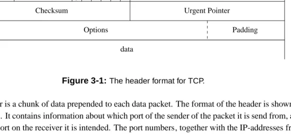
3.1.1 The TCP Header
0 Bit 16 Bit 32 Bit
Source Port Destination Port
Sequence Number Window Data Offset Reserved Urgent Pointer Checksum Padding Options data Acknowledgment Number FIN SYN RST PSH ACK URG
Figure 3-1:The header format for TCP.
The header is a chunk of data prepended to each data packet. The format of the header is shown in Figure 3-1. It contains information about which port of the sender of the packet it is send from, and to which port on the receiver it is intended. The port numbers, together with the IP-addresses from
3.1 The Protocol The Transmission Control Protocol
the IP header, uniquely identify a connection. Each byte in the data field has a Sequence Number attached to it. When multiple bytes are sent together in a packet, then the sequence number is the number of the first byte in the data field. When a connection is established a random number is chosen for the sequence number. This number is also called the Initial Sequence Number (ISN). This minimizes the possibility of mixing up delayed packets from a previous connection with the same ports and ip-addresses. The Acknowledgment Number contains the last byte received plus one, said in another way, the field contains the expected sequence number of the next packet to be received. In TCP it is not required that every packet received is acknowledged, but instead every byte transfered has been acknowledged.
The field named data offset is used to describe how many 32 bit words are currently present in the TCP header. The reserved field is not used and must be set to 0. The following 6 bits are used to determine what type of data is attached, and which fields in the packet are used. The first bit is the Urgent flag (URG), it signals that urgent mode is activated. The Acknowledge flag (ACK) indicates that this packet acknowledges some received data. The Push flag (PSH) is a reminiscence from early implementations of TCP. Its meaning is to push the data sent forward to the receiving appli-cation without waiting for further data. The Reset flag (RST) is a control flag that tell the peer that the connection has to be dropped, e.g. as a reply to a faulty synchronization. The Synchronize flag (SYN) is used to start the connection by synchronizing the two parts acknowledgment numbers. The Final flag (FIN) is used to signal that there is no more data from the sender. A packet with one of the flags set will be noted as being of that type, i.e. a SYN/ACK packet is a packet with the SYN and ACK flag set.
The Window field contains the size of the senders current data buffer, implying that no more data than that specified in this field can be sent to the sender. If the receiving TCP implementation has not yet delivered the data to the appropriate application, the window size will become smaller. In other words, this is the size of the data buffer subtracted the size of the data it contains. The Checksum field is used to minimize the risk of badly transferred data. The Urgent Pointer points to the last byte of urgent data. The Options field is a variable field. It can contain multiple options selected for the current packet. Each options may vary in size and Padding is applied in order to make the header be composed of 32-bit words.
The fields that are interesting for doing stateful inspection are those that change the state of the connection, identify the connection or somehow can be used to confirm the correctness of the connection. These fields are:
Source port and destination port, because they, together with the source and destination
address from the IP layer, uniquely identify the connection.
Sequence number and acknowledgment number, because they show the progress of the
con-nection.
The data length of a packet and window size are also needed for flow control which
deter-mines how a connection can progress.
The flags ACK, RST, SYN, FIN, because they determine and change the state of the
con-nection. 16
The Transmission Control Protocol 3.2 Connection Phases
Here we have provided an overview of what the TCP header contains. Most of the fields in the TCP header are used during the phases; connection establishment, data transmission, and connection termination, which are described in the following section. The other fields are not described any further.
3.2 Connetion Phases
A TCP connection session can be divided into three phases, namely establishing the connection, transmission of data and connection termination. In this section we will describe these phases. First we will consider some modeling issues and then move on to connection establishment.
The models
For each part we will make a TCA. In order to simplify the figures a special notation will be used. A transition with a “SYN!” is equal to “paket!^(paket:synflag=true)^(paket:akflag=
false)^(paket:finflag = false)^(paket:rstflag = false)”. As this is quite long and
there is no ambiguity with using the shorter version, the short version will be used. Likewise a
“FIN=ACK!” is a packet with both the FIN and the ACK flag set. Also, to avoid
misunderstand-ing “SYN!:ak” will be used instead of “paket:ak” to denote the acknowledgment field in the
packet.
There are a number of different variables that are used. “TYPE” is the type of role the machine takes. This is commonly determined by the implementation and can only be client or server. the “ack”, “seq”, “win”, and “dl” in the packet scope are respectively the acknowledgment field, the sequence number field, the window size field, and the data length of the packet. The data length is not a field in itself, however, it is calculated as the total length from the IP header subtracted the IP header length field from the IP header and data offset field from the TCP header of the current packet.
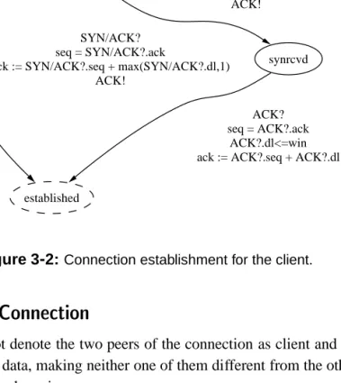
3.2.1 Connetion Establishment
Before data can be transferred between a client and a server, a connection must be established. In TCP this is done by synchronizing sequence numbers. The client sends a packet with the SYN flag set, and include the ISN in the packet. The server must reply to this packet with an ACK packet, acknowledging the ISN plus one, since a packet with the SYN flag set demands that the sequence number is incremented. This is shown in Figure 3-2 on the next page. However, until now the establishment have only been one way. A similar process is needed for the server, which is shown in Figure 3-3 on page 19. This implies that the server must send a packet to the client with the SYN flag set containing the servers ISN and the client to reply with an ACK. The established state is dashed because this is not the complete figure and more will follow.
The normal course is for the client to send its ISN and the server to respond with a SYN/ACK packet, which is an acknowledgment of the clients ISN and its own ISN. The client then responds with an acknowledgment of the servers ISN. However, TCP also allows both peers to initiate a con-nection at the same time. This means that they simultaneously sends their ISN and acknowledges the other’s ISN. These two scenarios would both result in the client considering its connection
3.2 Connection Phases The Transmission Control Protocol
established, called half-way open. As with the clients SYN packet, the SYN packet sent by the server must also be acknowledged in order to confirm that the client has received the right ISN. When that is done, the connection is established in both directions. The TCAs, Figure 3-3 on the next page and Figure 3-2, describes the server and the client actions during a synchronization.
TCP errors
Unfortunately, as packets can vanish on the network, due to a number of reasons, problems could arise. To compensate for any packet loss retransmissions are used. E.g. if the SYN packet sent by the client does not reach the server, the client will simply time out and retransmit its packet. If the packet lost was the ACK packet sent by the server, the result would be somewhat the same, the client would still time out and re-send its SYN packet and the server sends an ACK in response assuming that its previous ACK packet was lost. The IP layer can also cause what may seem as errors by e.g. delivering packets out of order.
start synsent SYN! established SYN/ACK? seq = SYN/ACK?.ack
ack := SYN/ACK?.seq + max(SYN/ACK?.dl,1) ACK!
synrcvd SYN?
ack := SYN?.seq + max(SYN?.dl,1) ACK!
ACK? seq = ACK?.ack
ACK?.dl<=win ack := ACK?.seq + ACK?.dl
Figure 3-2:Connection establishment for the client.
3.2.2 Established Connetion
In this section we will not denote the two peers of the connection as client and server, since they both transmit and receive data, making neither one of them different from the other. Therefore we instead call them sender and receiver.
In this phase of the connection data flows from the sender to the receiver. To ensure that the data arrives at the other end of the connection, it can be ordered, and that data is not duplicated we use 18
The Transmission Control Protocol 3.2 Connection Phases
listen
synrcvd
SYN?
ack := SYN?.seq + max(SYN?.dl,1) SYN/ACK!
established
ACK? seq = ACK?.ack ACK?.dl <= win ack := ACK?.seq + ACK?.dl
Figure 3-3:Connection establishment for the server.
the sequence number and acknowledgment number. The window size of the receiver is used to ensure that the sender does not send more that the receiver can receiver. If this is done anyway, the excess packets are not acknowledged. If a packet is missing, data following it will not be acknowledged until the missing packet has been received. Also acknowledgments themselves will not be acknowledged, only when new sequence number is presented, this will be acknowledged.
If a packet is lost it implies that the current information about the state of the sender is also lost. The sender, whose packet is lost, will, if the packet contained data, retransmit it as a result of the receiver not acknowledging the data. The unacknowledged data will first be acknowledged when the receiver retransmits the lost acknowledgment, is ready to transmit something else, or if additional data are sent from the sender. Until then, the retransmissions will be continued and they will be dropped as they are received.
Acknowledgments are not required to be sent right away when a packet is received, as TCP ac-knowledges the individual bytes continuously. If packets are transmitted from a client that has not yet acknowledged data, the ACK flag will be set and the acknowledgment number will contain the next sequence number to be received. In most implementations the peer, that has received data and not yet sent an acknowledgment, waits 200 ms before transmitting the acknowledgment. This is done in order to avoid transmitting additional data onto the network, since all the packets received within the 200 ms can be acknowledged in one packet and acknowledgments are piggy-backed onto other transmitted packets if possible. [Ste94]
3.3 TCA for a TCP Connection The Transmission Control Protocol
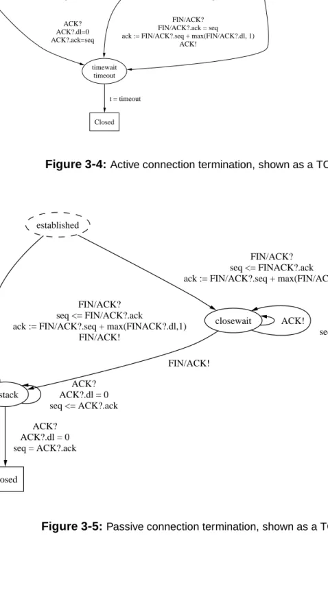
3.2.3 Connetion Termination
Finally as data has been transferred between the client and the server, the connection is ready to be closed. We consider the connection as two distinct connections, one from the client to the server and one from the server to the client.
The termination of the connection consists of two phases, the step to half-way open and the total close. Either one of the peers can at any time decide to end their connection. Neither of the phases are different from each other. The only exception is that the connection is defined as half-way closed after one has terminated the connection to the other and data can still be transferred in the direction that has not been closed.
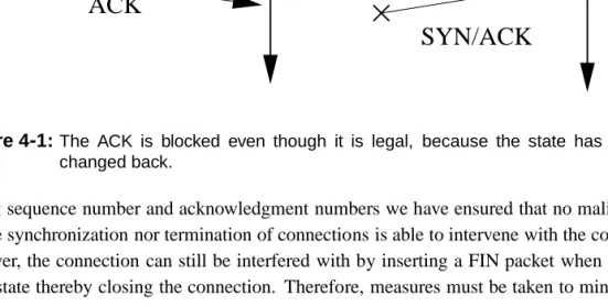
The connection termination is a two-way handshake. First, one of the sides, in our example the client, sends a packet with the FIN flag set. The server must reply to the FIN packet with an ACK packet containing the acknowledgment number incremented one from the sequence number, or if the received FIN packet contains data, the acknowledgment number must be increased by the value of the data length. Moreover, the server must consider if data has been lost between the last receive packet and the FIN packet received. As usual packets can vanish or be delayed and in that coincidence the packets must be retransmitted. The connection will be considered closed from the client to the server when the ACK packet is received by the client. The server closes its connection in the same manner. If the very last acknowledgment is lost, it will generate a retransmission of the FIN packet from the server to the client (as the server closes its connection last in our current example), however, the connection could already be thought of as closed. But in order to avoid that unnecessary packets are sent, the connection will be in a Closewait state. In theory it can be there forever, since no timeout period has been specified [Pos81].
In the coincidence of simultaneous closing, the only difference from the described is that both connections can not be sure that their last packet arrived at the other peer. Figure 3-4 on the next page and Figure 3-5 on the facing page depicts two TCA respectively describing the closing phase of the connection for both the client and the server, the client being the peer which actively closes the connection and the server which passively closes the connection.
3.3 TCA for a TCP Connetion
Here we present a TCA describing the entire TCP connection. The TCA is a concatenation of the previous depicted TCA. The model is depicted in Figure 3-6 on page 22 and we call this the TCP peer model.
There are a few remarks to the figure. Some transitions have been omitted in order to minimize the figure. Retransmissions are not modeled in the figure. Retransmissions are basically a loop on the same state, however, since two transitions can lead to the same state to avoid wrong modeling a workaround can be made by splitting the state in two, this is exemplified in Figure 3-7 on page 23. But as this would make the figure very large this have been omitted.
Also on every state succeeding the established state there are transitions with “ACK =R ST?^
seq = ACK =R ST?:ak” going to closed and loops with “ACK!^ACK!:seq+ACK!:dl >
ak+win^ak>ACK!:seq”, “ACK?^seq>ACK?:ak^ak:=ACK?:seq+ACK?:dl”
The Transmission Control Protocol 3.3 TCA for a TCP Connection established finwait1 FIN/ACK! ACK? ACK?.ack < seq finwait2 FIN/ACK? FIN/ACK?.ack < seq ack := FIN/ACK?.seq + max(FIN/ACK?.dl, 1)
ACK!
closing
ACK? ACK?.ack=seq ack := ACK?.seq + ACK?.dl
timewait timeout
FIN/ACK? FIN/ACK?.ack = seq ack := FIN/ACK?.seq + max(FIN/ACK?.dl, 1)
ACK! ACK?
ACK?.ack < seq ack := ACK?.seq + ACK?.dl
ACK? ACK?.dl=0 ACK?.ack=seq
ACK? ACK?.ack < seq ack := ACK?.seq + ACK?.dl
FIN/ACK? FIN/ACK?.ack = seq ack := FIN/ACK?.seq + max(FIN/ACK?.dl, 1)
ACK!
Closed t = timeout
Figure 3-4:Active connection termination, shown as a TCA.
closed
established
lastack
FIN/ACK? seq <= FIN/ACK?.ack
ack := FIN/ACK?.seq + max(FINACK?.dl,1) FIN/ACK!
closewait
FIN/ACK? seq <= FINACK?.ack
ack := FIN/ACK?.seq + max(FIN/ACK?.dl,1)
ACK? ACK?.dl = 0 seq = ACK?.ack ACK? ACK?.dl = 0 seq <= ACK?.ack FIN/ACK! ACK! ACK? ACK?.dl = 0 seq <= ACK?.ack
3 .3 T C A fo r a T C P C o n n e c tio n T h e T ra n s m is s io n C o n tr o l P ro to c o l start RST! listen TYPE = Server synsent TYPE = Client SYN! closed ACK? ACK/RST! SYN! synrecv SYN? ack := SYN?.seq + max(SYN?.dl,1)
SYN/ACK! ACK? seq < ACK?.ack ACK/RST! ACK/RST? seq = ACK/RST?.ack SYN? ack := SYN?.seq + max(SYN?.dl,1)
ACK!
established
SYN/ACK? seq = SYN/ACK?.ack ack = SYN/ACK?.seq + max(SYN/ACK?.dl,1)
ACK? seq < ACK?.ack ACK/RST! ACK/RST? TYPE = server seq = ACK/RST?.ack ACK? seq = ACK?.ack ACK?.dl <= win ack := ACK?.seq + ACK?.dl ACK!
ACK? seq > ACK?.ack ack := ACK?.seq + ACK?.dl
closewait FIN/ACK? seq <= FIN/ACK?.ack ack := FIN/ACK?.seq + max(FIN/ACK?.dl,1)
lastack FIN/ACK?
seq <= FIN/ACK?.ack ack := FIN/ACK?.seq + max(FIN/ACK?.dl,1)
FIN/ACK! finwait1 FIN/ACK! ACK? ACK?.dl = 0 seq <= ACK?.ack FIN/ACK! ACK? ACK?.dl = 0 seq = ACK?.ack ACK? ACK?.dl = 0 seq <= ACK?.ack finwait2 FIN/ACK? FIN/ACK?.ack < seq ack := FIN/ACK?.seq + max(FIN/ACK?.dl, 1)
ACK! closing
ACK? ACK?.ack=seq ack := ACK?.seq + ACK?.dl
timewait FIN/ACK? FIN/ACK?.ack = seq ack := FIN/ACK?.seq + max(FIN/ACK?.dl, 1)
ACK! ACK? ACK?.dl=0 ACK?.ack=seq FIN/ACK? FIN/ACK?.ack = seq ack := FIN/ACK?.seq + max(FIN/ACK?.dl, 1)
ACK! t = timeout F ig u re 3 -6 : T h is T C A s h o w s h o w a T C P c o n n e c tio n a c ts a s s p e c ifi e d . 2 2
The Transmission Control Protocol 3.4 Summary end a b 1 3 retransmission of 1 retransmission of 2 c 2 a b 1 retransmission of 1 end 3 c copy of b 2 retransmission of 2 3
Figure 3-7:The retransmission workaround.
and “ACK!^ak >ACK!:seq”. This is of course not on the closed state as this is an accepting
state.
3.4 Summary
In this chapter we have studied the TCP protocol with focus on the details that are important for stateful inspection. We have studied the connection phases and we have made a model for the behavior of each of the peers in a connection. This model represents a single peer and is the same for both peers.
CHAPTER4
In the previous chapter we looked at the behavior of TCP. From this behavior we derived a model of how a peer should react. In this chapter the behavior of TCP is examined from a stateful inspection firewall’s point of view and a new model is derived. Afterwards we address other problems concerning modeling stateful inspection. More specific, we focus on whether a firewall should be active or passive, and behavior of protocols that significantly differs from TCP. We will start by examining where the stateful inspection firewall is placed.
4.1 The Man In The Middle
Communication is between two points and it is somewhere between these points that a firewall exists. Where it is actually placed, be it closer to point A than point B or vice versa, does not matter since we only need to filter at some point between peers.
Considering an arbitrary network, literally millions of different routes could exist for a single message to travel in order to reach its destination. Virtually every message could travel its own route. This problem is eliminated by forcing packets to travel through that point, e.g. by making it physically impossible to go another way. This is necessary because the intention of a firewall is to ensure that unwanted traffic is filtered away and therefore all traffic must travel through the firewall. In other words, to get traffic in or out of the protected network everything have to pass the firewall and thereby we have to ensured that a firewall is always in between peers.
Considering communication on a network, a peer can only tell what it have received and send of messages. It is unknown to a single peer if messages send have actually been received by the other peer. Likewise a firewall only knows what messages it has seen, it does not know if the messages are actually received by a peer once it has seen them. To make matters even worse it is not guaranteed that a message sent before another will be received before the other.
4.2 Stateful Inspetion on TCP
As shown, TCP can be described as a TCA, which any valid TCP connection will conform to. So, in order to examine if any TCP connection is valid, it is a question of changing the state of the connection according to every received packet. We will now look at how we can use this information in order to create a TCA for how a stateful inspection firewall should react to a TCP connection.
As said previously, a connection viewed from a point in the network, be it the peers or in between them, it is only possible to say what has come through that point. The firewall, which is in the middle, does not know whether a packet it has seen is received by the receiver or if a response has
4.2 Stateful Inspection on TCP Stateful Inspection on TCP
been send, still it only knows what packets it has seen. We will take this into consideration as we look at what actually can be said about a connection when looking at it between peers.
It is imperative that the firewall does not assume anything about a connection as this could lead to wrong state change. This could lead to dropping of packets which should not have been dropped and ultimately blocking connections. Instead it must only react upon what is known. Causing a connection to hang must also be avoided at any cost as this can have disastrous effect on the application which is using the connection. The main goal is to minimize the number of false positives and positive negatives, in other words, the number of wrongly blocked packets and the number of accepted packets which does not belong to the connection. All this will be taken into consideration as we look at how to design a stateful inspection firewall for TCP.
4.2.1 Handshakes
The initializing handshake is a three-way handshake or two two-way handshakes. First there is no connection in which the state is equal to the TCP state Listening and Start depending on whether it is the server or client. Then a SYN packet is sent from the client to the server and the connection then changes state equal to the Synsent. We will always consider the client to be the one which first sent a SYN packet, even if it is a simultaneous connection establishment. The server then receives the packet and responds with an ACK to the SYN and sends a SYN itself, commonly done by a combined SYN/ACK packet. Again the connection changes state accordingly to what has been send. Similar in the case of simultaneous connection establishment both peers change state accordingly.
Similar the handshakes used to close the connection changes the state of the connection. Again, as it is not specified who sends the first FIN packet, both scenarios have to be taken into account, and also simultaneous FINs. As with TCP there are transitions that allow state changes. By filtering out packets which are not a legal state change packet, it is possible to securely make rules for opening and closing connections.
In both cases we check that the acknowledgments acknowledges the correct sequence number. This is done by storing the sequence number from the SYN packets and waiting for the corre-sponding acknowledgments. After synchronization this is done by checking that the data length plus sequence number is equal to the acknowledgment number.
Retransmission should also be allowed through the firewall. To do this a looping state change is used to allow the last seen packet through the firewall. How retransmissions are handled in an established connection is a more difficult task and we need more information to handle this, therefore we will come back to this later.
However, due to retransmissions it is not always easy to inspect a connection between peers. Consider the following example:
Example 3 A client initiates a connection by sending a SYN. This is registered by the firewall. The server replies with SYN/ACK, which the firewall also registers and now waits for an ACK. However, the client times out before receiving the SYN/ACK and retransmits the SYN. There are two possible actions by the firewall when it sees the SYN, either it can change back to its previous state or remain in the same state.
Stateful Inspection on TCP 4.2 Stateful Inspection on TCP
Intuition dictates changing states. If this is done, the server responds again with a SYN/ACK and the connection changes state again and proceed as normal. However, it is not known if the server’s SYN/ACK actually was received by the client, if it was the client would think that it is a respond to the retransmission and send an ACK. If the servers respond to the retransmission was somehow lost before reaching the firewall, the firewall still expects a SYN/ACK from the server but gets an ACK from the client which would be regarded as false and therefore be dropped as it would not invoke a legal state change.
The transmission of packets is illustrated in Figure 4-1. Although this would not halt the connec-tion, a legal ACK is blocked and this must never happen. Therefore the state must remain the same even after seeing a SYN/ACK from the server and getting a SYN from the client and none of the packets must be dropped.
Client
Firewall
Server
SYN
SYN
SYN/ACK
ACK
SYN/ACK
Figure 4-1:The ACK is blocked even though it is legal, because the state has changed back.
By checking sequence number and acknowledgment numbers we have ensured that no malicious packet in the synchronization nor termination of connections is able to intervene with the connec-tion. However, the connection can still be interfered with by inserting a FIN packet when in the established state thereby closing the connection. Therefore, measures must be taken to minimize this risk.
4.2.2 Window Size and Sequene Numbers
The goal of connection establishment phase is to synchronize the sequence numbers. The sequence number is then used to determine whether all packets have been received or not.
Simple state inspection would be to change the state every time a higher sequence number has been seen and when these have been acknowledged. This works well with TCP, but as IP does not guarantee that packets are received in the order in which they were sent this would lead to dropping of out-of-order packets.
4.2 Stateful Inspection on TCP Stateful Inspection on TCP
“IP Filter” used with the BSD operating system dropped these out-of-order packet. Guido van Rooij suggest a solution for this problem [Roo00]. In his article he suggest four different bound-aries for packets, an upper and a lower for data and an upper and a lower for acknowledgments. In deriving the boundaries we consider two hosts, A and B, communicating via TCP and a firewall, F, in between. Host A sends data to host B which then in turn acknowledges the data. We know that if the roles where switched the boundaries would be symmetric and therefore we will only consider data in one direction. First we will consider the data boundaries.
Data Boundaries
For any given packet,sis the sequence number andnis the length of the data. The notations
Bis
host B’s sequence number andn
B is the data length of the packet from B. We know that we are
not allowed to send more data than the receiver can accept and thus the upper boundary for a given data packet is this:
(last byte in packet)(maximum byte that host A is allowed to send)
The last byte in a packet is known to be the same as the sequence number plus the data length of the packet. The maximum byte that A is allowed to send is the last acknowledged number from B,ak
B, plus the last window size from B, win
B, which host B has send and has been seen by
A. The functionlast A
(x)returns the lastxseen byA, e.g.last A
(s B
)is the last sequence number
from host B that A has seen. Note that the last is not same as the current. From this we get:
s A +n A last A (ak B )+last A (win B ) (4-1)
There is an exception to 4-1. When a window size of zero is announced by host B, host A will start a so-called persist timer that probes host B for a non-zero window size. This is done by periodically sending 1 byte data packets to B until a response packet from B containing a non-zero window has been seen by A [SW95, page 827]. This is the only exception to the data boundaries [Pos81, section 1.5]. The functionmax(x;y)returns the larger ofxandy. From this the upper boundary
is: s A +n A last A (ak B )+last A (max(win B ;1)) (4-2)
Considering the firewall in the middle we can also say that this holds for the firewall. Thus we get the upper boundary for what the firewall should accept:
s A +n A last F (ak B )+last F (max(win B ;1)) (4-3)
Moving on to the lower boundary we know that host A will only send data that has not been acknowledged and thus we have:
s A last A (ak B ) (4-4) 28
Stateful Inspection on TCP 4.2 Stateful Inspection on TCP
If we change the point of view from host B to host A in 4-2 we get:
last B (s A )+last B (n A )last A (ak B )+last A (max(win B ;1)) (4-5)
Combining 4-5 with 4-4 we get:
s A last B (s A )+last B (n A ) last A (max(win B ;1)) (4-6)
Finally if we move the point of view to the firewall we will see that the following holds and our lower data boundary for the firewall is:
s A last F (s A )+last F (n A ) last F (max(win B ;1)) (4-7) Aknowledgment Boundaries
We now move on to host B acknowledging data from host A. The notationa
Bis the
acknowledg-ment number of the current packet which we are examining from host B. Considering what the upper boundary for acknowledgments is we know that data which have not been sent can not be acknowledged. Thus we get:
a B last B (s A )+last B (n A ) (4-8)
Again, considering this from the firewall point of view we get the upper boundary for the firewall:
a B last F (s A )+last F (n A ) (4-9)
Matters are however complicated when considering the lower boundary for acknowledgments. In-tuitively we know that there is no need to acknowledge data which has already been acknowledged and we can use the boundary:
a B last B (ak B ) (4-10)
However, we do not know if packets arrive out-of-order. If two acknowledgment packets arrive out-of-order the packet which is out of bound will be blocked. As we do not want to interfere with a protocol behaving properly, as is the case, we need to refine our view of the lower boundary. We define a new value which we callMAXACKWINDOW. This value is slightly greater than the
maximum value of a TCP window size. Using this we get:
a B last B (s A )+last B (n A ) MAXACKWINDOW (4-11)
By making MAXACKWINDOW larger than the maximum possible TCP window size we
have ensured that no valid ACK is blocked. The observation is that all the data in the window is potentially being acknowledged, under the window everything is acknowledged and everything
4.3 The Stateful Inspection Model Stateful Inspection on TCP
above is unacknowledged. Although this is not an optimal solution it is close enough as we are sure that no packet is wrongly blocked and at the same time we know that acknowledgments to data which has already been acknowledged will be ignored by the receiver. When considering it from the firewall we get:
a B last F (s A )+last F (n A ) MAXACKWINDOW (4-12)
Using the boundaries
The boundaries are fairly simple to test and each packet that passes the firewall will be tested for each boundary. If a packet, that is not within these boundaries, is received by the firewall, it is dropped. With this the window of possible malicious packets getting through is minimized. Alas, the window can not be removed entirely because packets can arrive out of order. The four boundaries are as follows.
Upper Data Boundary s A +n A last F (ak B )+last F (max(win B ;1))
Lower Data Boundary s A last F (s A )+last F (n A ) last F (max(win B ;1))
Upper Acknowledgment Boundary a B last F (s A )+last F (n A )
Lower Acknowledgment Boundary a B last F (s A )+last F (n A ) MAXACKWINDOW
Using all the above stated boundaries the connection is reasonably secured from malicious data, however, the network media is volatile and may corrupt the connections to an extend where they must be terminated. This termination is handled by the special reset (RST) packets and these also have to be accounted for.
4.2.3 Resetting the Connetion
As described, RST packets must be allowed to pass through the firewall since they are an essential part of the protocol. An example of when a RST packet is sent follows: when a client sends a SYN which the server receives and an old SYN is then received by the server afterwards. The server does not know which of these SYNs it should react to so it sends a RST packet. In this case the connection should be dropped. Likewise there are other scenarios where a RST is allowed. Of course a connection should not be terminated just because a RST is received, the RST must have been sent by one of the peers and must be validated by checking that the RST acknowledges the right sequence number. This is similar to the TCP peer model, Figure 3-6 on page 22. Instead of going to the closed state, where all stored information about the connection is removed, the transition goes to the timewait state, because of retransmissions.
4.3 The Stateful Inspetion Model
In section 4.2 we have considered the SYN, ACK, FIN, and RST flags of the TCP header. We have also considered the sequence number field, acknowledgment number field, the packet data 30