http://researchcommons.waikato.ac.nz/
Research Commons at the University of Waikato
Copyright Statement:
The digital copy of this thesis is protected by the Copyright Act 1994 (New Zealand). The thesis may be consulted by you, provided you comply with the provisions of the Act and the following conditions of use:
Any use you make of these documents or images must be for research or private study purposes only, and you may not make them available to any other person. Authors control the copyright of their thesis. You will recognise the author’s right
to be identified as the author of the thesis, and due acknowledgement will be made to the author where appropriate.
You will obtain the author’s permission before publishing any material from the thesis.
Techniques for Failure Recovery in
a Software-Defined Network
A thesis
submitted in fulfillment of the requirements for the degree
of
Master of Science
in
Computer Science
at
The University of Waikato
by
Christopher Lorier
Department of Computer Science Hamilton, New Zealand
August 18, 2014
c
Abstract
As our lives become ever more dependent on network connectivity, it be-comes increasingly more important for networks to be able to overcome the failure of individual components and continue to function. This the-sis examines approaches to fault tolerance in software defined networks, and how the global viewpoint that Software Defined Networking (SDN) provides can be leveraged to create more reliable networks.
In order to continue operation after the failure of a network component, the failure must first be detected, and then the network must automati-cally change its behaviour to mitigate any adverse consequences. This the-sis evaluates a variety of fault detection methods and potential responses. Based on these evaluations the design for a fault tolerance system for soft-ware defined networks is presented. This system builds protected paths usingRing Based Forwarding, an algorithm for creating a full mesh of paths between switches in a network where each path has a fail-over path at each hop. The system monitors the network for faults using Traffic Colouring, a technique for passively monitoring network traffic.
Acknowledgments
I would like to thank everyone that has helped me throughout this thesis— especially Brad Cowie, Shane Alcock, Brendon Jones, Richard Nelson, Josh Bailey and Perry Lorier.
Contents
1 Introduction 1 1.1 Document Structure . . . 4 2 Background 7 2.1 RouteFlow . . . 7 2.1.1 Distributed RouteFlow . . . 8 2.1.2 Fault Tolerance . . . 8 2.2 OpenFlow . . . 9 2.2.1 OpenFlow Versions . . . 9 2.2.2 OpenFlow Ports . . . 10 2.2.3 Flow Tables . . . 10 2.2.4 Group Tables . . . 11 2.2.5 OpenFlow Statistics . . . 122.2.6 The OpenFlow Protocol . . . 12
2.3 OpenFlow Switch Implementations . . . 13
3 Evaluation of Previous Work 15 3.1 Fault Detection . . . 15
3.1.1 Bidirectional Forwarding Detection . . . 16
3.1.2 Automatic Test Packet Generation . . . 17
3.1.3 Topology Aware Blackbox Monitoring . . . 18
3.1.4 A Packet Based Method for Passive Performance Moni-toring . . . 19
3.1.5 Realistic Passive Loss Measurement for High-Speed Net-works . . . 21
3.1.6 Summary of Existing Work in Fault Detection . . . 21
3.1.7 Conclusion . . . 23
3.2 Fault Recovery . . . 23
3.2.1 Method and Apparatus for Determining Multiple Minimally-Overlapping Paths . . . 24
3.2.2 FatTire: Declarative Fault Tolerance for Software-Defined Networks . . . 25
3.2.3 Network Architecture for Joint Failure Recovery and Traffic Engineering . . . 25
3.2.4 Automatic Failure Recovery for Software-Defined Net-works . . . 26
3.2.5 Summary of Existing Work in Fault Recovery . . . 27
3.2.6 Conclusion . . . 27 4 Fault Detection 29 4.1 Traffic Colouring . . . 29 4.1.1 Packet Labelling . . . 30 4.1.2 Flow Tables . . . 31 4.1.3 Locating Faults . . . 34 4.1.4 Statistics Retrieval . . . 35 4.1.5 Controller Module . . . 35
Contents ix
4.1.6 Counter Accuracy . . . 37
4.2 Test Packet Injection . . . 38
4.2.1 Packet Labels . . . 39
4.2.2 Sending Probes . . . 39
4.2.3 Switch Configuration . . . 40
4.2.4 Probe Timing and Statistics Requests . . . 41
4.2.5 Controller Module . . . 42
4.2.6 Barriers to Implementation . . . 42
5 Fault Response 43 5.1 Forwarding Rings . . . 44
5.2 Pairs of Minimally Overlapping Paths . . . 48
5.3 Minimal Pairs of Minimally Overlapping Paths . . . 55
5.3.1 Algorithm i . . . 56
5.3.2 Algorithm ii . . . 60
5.4 Ring Based Forwarding . . . 62
6 Evaluation 67 6.1 Fault Detection . . . 67
6.1.1 Speed of Detection . . . 68
6.1.2 Flow Table Requirements . . . 70
6.1.3 Controller Load Requirements . . . 70
6.1.4 Network Load . . . 72
6.1.5 Locating Faults . . . 72
6.1.6 Other Considerations . . . 72
6.1.7 Conclusion . . . 73
6.2 Fault Recovery . . . 74
6.2.2 Primary Path Length . . . 74
6.2.3 Alternate Path Length . . . 77
6.2.4 Flow Table Entries . . . 79
6.2.5 Link Load . . . 85 6.2.6 Other Considerations . . . 87 6.2.7 Conclusion . . . 88 6.3 Conclusion . . . 88 7 Conclusion 91 7.0.1 Contributions . . . 92 7.0.2 Future Work . . . 93 References 95
List of Tables
List of Figures
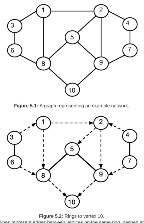
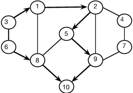
5.1 A graph representing an example network. . . 48
5.2 Rings to vertex 10. . . 48
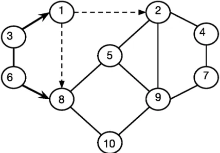
5.3 Step 1 of building paths to vertex 10 for the vertices on ring 4. . 49
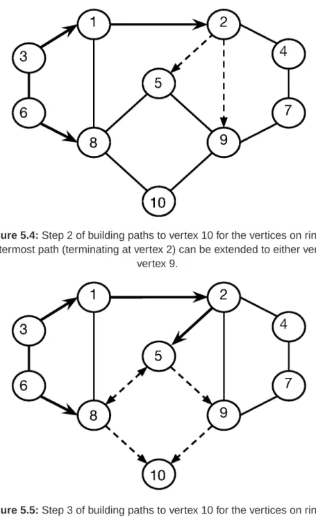
5.4 Step 2 of building paths to vertex 10 for the vertices on ring 4. . 50
5.5 Step 3 of building paths to vertex 10 for the vertices on ring 4. . 50
5.6 The final paths to vertex 10 for the vertices on ring 4 . . . 51
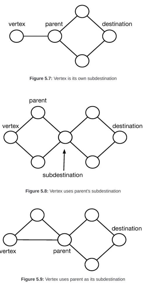
5.7 Vertex is its own subdestination . . . 54
5.8 Vertex uses parent’s subdestination . . . 54
5.9 Vertex uses parent as its subdestination . . . 54
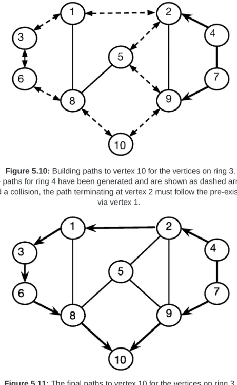
5.10 Building paths to vertex 10 for the vertices on ring 3. . . 57
5.11 The final paths to vertex 10 for the vertices on ring 3. . . 57
5.12 Rings to vertex 10 rearranged to demonstrate vertex locations. . 61
5.13 Paths to vertex 10 for the vertices on ring 3. . . 61
6.1 Controller traffic per cycle. . . 71
6.2 Mean primary path length in networks of 20 switches . . . 75
6.3 Mean primary path length in networks of 100 switches . . . 76
6.5 Mean alternate path length in networks of 20 switches . . . 78 6.6 Mean alternate path length in networks of 100 switches . . . 78 6.7 Mean alternate path length in networks of 500 switches . . . 79 6.8 Mean flow table entries per switch in networks of 20 switches . 80 6.9 Mean flow table entries per switch in networks of 100 switches 80 6.10 Mean flow table entries per switch in networks of 500 switches 81 6.11 Max flow table entries per switch in networks of 20 switches . . 82 6.12 Max flow table entries per switch in networks of 100 switches . 82 6.13 Max flow table entries per switch in networks of 500 switches . 83 6.14 Flow table entries per switch in networks of 20 switches and 30
links . . . 84 6.15 Flow table entries per switch in networks of 100 switches and
150 links . . . 84 6.16 Flow table entries per switch in networks of 500 switches and
750 links . . . 85 6.17 Paths per link in networks of 20 switches and 30 links . . . 85 6.18 Paths per link in networks of 100 switches and 150 links . . . . 86 6.19 Paths per link in networks of 500 switches and 750 links . . . . 86
List of Algorithms
5.1 Forwarding rings algorithm pseudo-code . . . 45
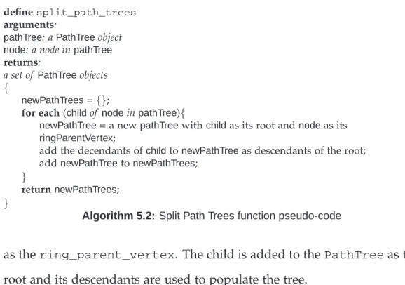
5.2 Split Path Trees function pseudo-code . . . 47
5.3 Path Pairs algorithm pseudo-code . . . 52
5.4 Overlapping paths algorithm pseudo-code . . . 53
5.5 Shared Paths algorithm i pseudo-code. . . 58
5.6 Shared Paths algorithm ii pseudo-code . . . 64
Acronyms
AFRO Automatic Failure Recovery for OpenFlow
ATPG Automatic Test Packet Generation
BFD Bidirectional Forwarding Detection
CDF Cumulative Distribution Function
CIDR Classless Inter-Domain Routing
DSCP Differentiated Services Code Point
IP Internet Protocol
IPv4 IP version 4
LSP Label Switched Path
MPLS Multiprotocol Label Switching
OFP OpenFlow Protocol
OSPF Open Shortest Path First
RSTP Rapid Spanning Tree Protocol
RTT Round Trip Time
SDN Software Defined Networking
SLA Service Level Agreement
TC Traffic Class
TCAM Ternary Content-Addressable Memory
VC Virtual Circuit
VLAN Virtual Local Area Network
1
Introduction
High availability is one of the most fundamental requirements of any com-puter network. When there is a fault in a network component, such as a router or cable, it is important that the network is able to continue operation with as little disruption to the network’s users as possible. This requires detecting and reacting to faults as quickly as possible, and responding in a manner that minimises the reduction in performance of the network. SDN is a new methodology for managing networks that shifts the control of a network from the devices that comprise that network to software running on a central server. This gives network operators an unprecedented level of control over the behaviour of their network and has generated a large amount of interest in the research community. However, in order to see widespread deployment SDN must be able to match or improve upon the reliability of existing networks.
The global viewpoint of the control software in a software defined network may allow new tools to be developed to improve the reliability of
net-works. This thesis explores potential methods of detecting and responding to faults that could be the basis for such tools.
The target application for this research is RouteFlow (Stringer, Fu, Lorier, Nelson, & Rothenberg, 2013), an open-source software defined routing ar-chitecture. RouteFlow controls a fabric of OpenFlow switches so that they behave as a single logical IP router. Aggregating switches into a single layer 3 device reduces configuration, simplifies the network structure and helps ensure that all the devices share a consistent policy. However, there is very little fault tolerance built into RouteFlow, making it unsuitable for deployment in a production environment. This thesis evaluates existing work in fault detection and recovery and presents a design for a fault tol-erance system for RouteFlow based on the results of that evaluation. This system will allow RouteFlow to continue to function in the face of network failures with as close to normal performance as possible.
The primary aim of this system is to detect faults in the underlying net-work hardware that causes behaviour that is inconsistent with the netnet-work configuration. While software faults and misconfiguration are the causes of the majority of network faults it is also important to verify the integrity of the hardware. The most common faults in network hardware are complete failures of a device or link, but faults may also exhibit more esoteric symp-toms such as partial packet loss, packet duplication or packet corruption and may only affect some packets but not others.
The evaluation of the system is based on the following requirements:
Minimal Impact: The system should not cause a significant reduction of
per-formance to RouteFlow when running on a fault free network.
3
network faults should be comparable to existing protocols such as OSPF (Goyal, Ramakrishnan, & Feng, 2003) or RSTP (IEEE, 2001). Faults should be detected within seconds and once the fault is dis-covered the operation of the network should be restored within mil-liseconds.
Accurate: The system must be able to detect as wide a variety of potential
faults as possible with minimal false positives.
Scalable: The state requirement for each switch in the network should scale
at a linear rate with the number of switches in the network and the load on the control software should be kept to a minimum.
Minimal Configuration: One of the advantages of an aggregated router is that
multiple devices can be configured by configuring one virtual router. It is important that the fault tolerance system must not require oner-ous configuration that would undermine this advantage.
Versatile: The system must be able to function effectively regardless of the
topology of the network.
An initial review of existing work was performed to identify potentially suitable methods of detecting and recovering from faults. Implementations of these methods were then created for further evaluation. Two methods of fault detection were implemented: Traffic Colouring, a method for passively monitoring traffic on a network by assigning packets a colour and com-paring the number of packets of each colour seen at various points in the fabric; and Test Packet Injection, a method of detecting faults by injecting probe packets into the fabric. For fault recovery methods the initial re-view resulted in the decision to use protected Virtual Circuits (VCs). Three algorithms for building protected paths for the VCs were created and
im-plemented for further evaluation: Path Pairs, a method for building pairs of minimally overlapping paths between switches on a network; Shared
Paths, a method for building pairs of minimally overlapping paths between
switches with the added constraint that no switch will ever require more than two forwarding rules to send all traffic to a given destination; and
Ring Based Forwarding, a method for building a path between each switch
in a network to a given destination switch with redundancy at every hop. Experiments were set up to further evaluate these methods and the results of these experiments were used to present a final design for a fault tol-erance system for RouteFlow. This system uses ring based forwarding to build paths and traffic colouring to detect faults.
1.1 Document Structure
Chapter 2 describes the RouteFlow architecture, the OpenFlow standard
used by RouteFlow and the OpenFlow switch implementations used during the work carried out for this thesis.
Chapter 3 examines existing work in fault detection and recovery to
iden-tify potential approaches that may be suitable for use with RouteFlow. The most promising approaches are selected for further evaluation.
Chapter 4 gives a detail description of implementations of the approaches
to fault detection chosen for further evaluation in Chapter 3.
Chapter 5 describes implementations of the approaches to fault recovery
created for this thesis. These implementations are based on approaches selected for further evaluation in Chapter 3.
1.1 Document Structure 5
described in Chapters 4 and 5. A final design of a fault tolerance system for RouteFlow based on the outcomes of these evaluations is presented.
Chapter 7 summarises the work undertaken for this thesis and its outcomes
2
Background
In this chapter some of the prior work that this thesis builds upon is ex-plained in detail. Firstly, the RouteFlow architecture is described, then the OpenFlow (McKeown et al., 2008) features relevant to this thesis are explained and finally the limitations of the OpenFlow switch implementa-tions used during this thesis are described.
2.1 RouteFlow
RouteFlow is an open source software-defined IP routing architecture. It controls a fabric of OpenFlow switches to act as a single logical router. RouteFlow consists of a Linux Virtual Machine (VM) running routing soft-ware, for instance Quagga (Free Software Foundation, n.d.) or BIRD (Filip, Forst, Machek, Mares, & Zajicek, 2010). The ports of the VM are mapped to the external ports of switches in the fabric. When the switches receive control plane traffic on a port it is redirected to the corresponding port on the VM. The routing software on the VM uses this traffic to learn routes,
and these routes are installed into the VM’s routing table as though the VM had received the control plane traffic directly. RouteFlow then learns the routes from the VM’s routing table and modifies the switches so that the entire fabric emulates the forwarding behaviour of the VM.
2.1.1 Distributed RouteFlow
In order to control a fabric of multiple OpenFlow switches to behave as a single IP router, VCs are created between each switch to each other switch on the fabric (Lorier, 2013). When data plane traffic arrives at a switch that matches a route that leaves the fabric on another switch, the traffic is forwarded through the VC to the correct egress switch where it is output. The VCs are implemented as Label Switched Paths (LSPs) using Multipro-tocol Label Switching (MPLS) labels. Virtual Local Area Network (VLAN) tags are used if the switches in the fabric do not fully support MPLS op-erations. The VC paths follow the shortest path between the switches, calculated using Dijkstra’s algorithm.
In order to reduce the number of flow table entries required to implement these paths, the LSPs share labels whenever possible. So that all traffic for a particular destination exiting any switch will share the same MPLS label whether it originated at that switch or arrived at that switch as part of a VC. The next switch in the path only needs to have one flow table entry to match all traffic for each destination, rather than a separate entry for every VC.
2.2 OpenFlow 9
2.1.2 Fault Tolerance
The fault tolerance of RouteFlow when controlling a multiple switch fabric is very poor. The only fault in the fabric that RouteFlow is able is when the controller loses the connection to one of the switches. This represents a small proportion of the possible faults that the system should be capable of dealing with. Other faults, such as link cuts, will never be detected and will result in all traffic that is sent over that link to be lost.
RouteFlow responds to the loss of the connection to a switch by setting every port on the VM associated with that switch to be down and then recalculates the path taken by every VC that passes through that switch and installs the new paths onto the switches. This is a very slow way of correcting the issue as every switch on every affected path needs to be updated before the traffic can be changed. There may be many affected paths and each is repaired one at a time.
2.2 OpenFlow
OpenFlow (McKeown et al., 2008) is a standard for the control of switches in a software defined network. It includes a specification (Open Network-ing Foundation, 2013) for switches to allow them to be controlled remotely in software with use of the OpenFlow Protocol (OFP). The remote software is referred to as thecontroller.
In this section the features of the OpenFlow standard that are relevant to this thesis are described.
2.2.1 OpenFlow Versions
RouteFlow supports OpenFlow version 1.2 (Open Networking Foundation, 2011), but at the time of writing the latest OpenFlow version is 1.4 (Open Networking Foundation, 2013). Because most of the features used by RouteFlow are compatible between versions 1.4 and 1.2 the work carried out as part of this thesis uses OpenFlow version 1.4.
2.2.2 OpenFlow Ports
Ports on OpenFlow switches can be physical or logical ports. Each port collects statistics on the traffic passing through it and has a state. The state is changed by the switch and includes the OFPPS_LIVE flag, which
is used with fail-over group tables, and theOFPPS_LINK_DOWNflag which is used to indicate that the physical link is not present. The port is live when the OFPPS_LINK_DOWN flag is not set, but can also be disabled by code running on the switch not specified by the OpenFlow standard. This allows the switch to support protocols such as Bidirectional Forwarding Detection (BFD) (Katz & Ward, 2010). Whenever the port state changes the controller is notified with aOFPT_PORT_STATUS message.
2.2.3 Flow Tables
The packet handling behaviour of OpenFlow switches is defined by adding entries to the switches’ flow tables. Flow table entries have a priority value, a cookie value, matches, and actions. When a packet arrives at the switch, the first flow table is searched for the matching entry with the highest priority. The matches consist of a list of masked values for match fields that specify which packets this entry can be applied to. Match fields include
2.2 OpenFlow 11
packet header fields as well as in port and metadata, which can be applied to packets as they are processed. Once the matching entry is found, the entry statistics are updated and the actions from the entry are applied to the packet. Actions include modifying packet headers, adding metadata, sending the packet to another table and outputting the packet to a port or dropping it. The cookie value is used to identify particular flows when they are being modified or when retrieving statistics from them.
While the implementation of the flow tables is entirely left in the hands of the vendor, the requirement for masked matches means that, in hardware, the flow table is typically implemented using Ternary Content-Addressable Memory (TCAM). TCAM performs masked value look-ups quickly, but is expensive in terms of price and power. Because of this flow tables are often limited in terms of the number of flows they can contain.
2.2.4 Group Tables
Group tables are tables that contain a list of action buckets, each containing separate sets of actions. When a packet arrives at a group table, the action buckets are applied to the packet based on the group type. There are several group types, the most relevant for this thesis are the all type and the optionalfast fail-overand selecttypes.
The all group, as the name suggests, creates copies of the packet for each bucket in the group and performs that bucket’s actions on the copy.
In a fast-failover group buckets are ranked and are associated with a port (or another group) to indicate its liveness. The actions from the first live bucket are applied to the packets. As the name suggests this allows for a quick response to a failure of a port.
The select type group choses one bucket to apply the actions on based on weights applied to each bucket. The selection is based on a hash of the packet headers to ensure flows follow the same path, but how this is im-plemented is up to the vendor. Buckets in the select group can implement a liveness mechanism similar to the fast fail-over group.
2.2.5 OpenFlow Statistics
Tables, individual flow entries and ports all keep statistics on network traf-fic. Flow table entries count the number of packets and the byte count of matching flows. Tables record the number of look-ups and the number of matches. Ports have separate counters for packets received and packets transmitted, each recording the number of packets, the number of bytes, the number of drops and the number of erroneous packets.
2.2.6 The OpenFlow Protocol
The OpenFlow Protocol defines the messages used by controllers to com-municate with OpenFlow switches.
The messages used in the work carried out for this thesis are described below.
Modify Flow Entry Messages
TheOFPT_FLOW_MOD message is used to modify the flow table entries on a switch.
Barrier Messages
Barrier messages are used to notify the controller that messages have been succesfully processed. The controller sends a OFPT_BARRIER_REQUEST
2.2 OpenFlow 13
message to the switch, which processes any messages it received before the barrier request before sending aOFPT_BARRIER_REPLYmessage back to the controller.
Multipart Messages
The messages used to collect statistics from the switches can be large for a single OFP message, which are limited to 64KB. As a consequence statis-tics requests and replies are carried in Multipart messages. The OFPT_ MULTIPART_REQUEST message is used by the controller to request statis-tics from the switch. The switch then replies with a OFPT_MULTIPART_ REPLYmessage containing the relevant statistics.
All OpenFlow messages contain a xid field to identify the transaction. OFPT_MULTIPART_REPLY messages use the samexidas the
correspond-ingOFPT_MULTIPART_REQUESTmessage to allow the controller to match the reply to the request.
Port Status Message
When the state of a port is modified, or a port is added or deleted from an OpenFlow switch, the switch will generate aOFPT_PORT_STATUS mes-sage to inform the controller of the change.
Packet-Out Message
TheOFPT_PACKET_OUT message is used by the controller to output pack-ets from one of the switches it controls. The OFPT_PACKET_OUT message
contains the packet data, as well as a set of actions for the switch to apply to the packet. This can include sending the packet to the first OpenFlow table for processing or to a group table.
2.3 OpenFlow Switch Implementations
The OpenFlow switch implementations available for use during the work for this thesis were Open vSwitch (Pfaff et al., 2009), an open source pro-duction quality software switch and Pronto 3290 and 3780 switches made by pica8. The Prontos run PicOS (Pica8 Inc., 2014), a hardware-agnostic Linux derived operating system for open switches based on Open vSwitch. Both of these switches offered partial support for OpenFlow versions up to 1.3 at the time the work for this thesis was being carried out.
Because both of these implementations are based on the same software, they share many of the same problems. Some features were not supported while the work for this thesis was being carried out: group tables and most MPLS actions were not supported and the collection of statistics from flow table entries in both systems had bugs that caused erroneous results to be returned in certain situations. In addition to these problems PicOS also has a faulty implementation of multiple tables that causes priorities on all tables but the first to be ignored. This effectively rendered multiple table implementations impossible on the Pronto switches.
3
Evaluation of Previous Work
Resilience is one of the most important properties of a network and as a consequence there is a large body of work in this area, including within SDN. In this chapter existing work is evaluated for its suitability for use in the RouteFlow architecture. Firstly, existing fault detection techniques will be evaluated. This evaluation will focus on speed of detection; scalability, both in terms of switch state and controller load; comprehensiveness of detection; and practicality in terms of implementation in OpenFlow. Sec-ondly, approaches to mitigation of these faults will be examined to deter-mine their suitability for use with the fault detection techniques chosen and with the RouteFlow architecture.
3.1 Fault Detection
Much of the previous work in fault resilience in OpenFlow has focussed on proving the correctness of the controller software and the configuration of switch flow tables (e.g., Al-Shaer & Al-Haj, 2010; Guha, Reitblatt, & Foster,
2013; Mai et al., 2011). This is a reflection of the fact that in traditional networks most network faults are caused by software bugs or misconfig-uration. However, proving the setup is correct is pointless if faults in the underlying layers result in actual behaviour that is different to what is configured. In the context of a network running RouteFlow it is more im-portant to be able to verify the actual behaviour of the network itself rather than the correctness of the configuration.
In this section existing methods for discovering faults in networks are sum-marised and evaluated for use with RouteFlow.
3.1.1 Bidirectional Forwarding Detection
There has been a lot of investigation into the performance of BFD (Katz & Ward, 2010) with fast fail-over groups and whether an OpenFlow network is able to meet the requirements of carrier-grade networks (e.g., Sharma, Staessens, Colle, Pickavet, & Demeester, 2013a, 2013b). Carrier-grade net-works have Service Level Agreements (SLAs) specifying levels of availabil-ity, typically 99.999%, and failure recovery time, typically less than 50ms, that must be met. While speed of recovery is an important goal for the work undertaken in this thesis, a 50ms response time is not necessary. Slower re-covery could be acceptable if it allows meeting other goals listed in Chapter 1. For instance a slower solution may be more suitable if it reduces the con-figuration needed.
In Fast Failure Recover for In-Band OpenFlow Networks Sharma et al. (2013a)
found that the 50ms recovery requirement could be achieved with the use of fast fail-over groups and BFD as the liveness detection mechanism. Be-cause network faults in an in-band controlled network could affect both the traffic passing through the network and the control traffic between the
3.1 Fault Detection 17
switches and the controller, it was found that the fail-over paths need to be pre-established for both the control plane traffic and the data plane traffic. The use of BFD, however, is inappropriate for this context as it requires additional configuration to be applied to each switch. The OpenFlow spec-ification has no mechanism for the configuration and initiation of BFD or any other liveness mechanism. While the controller could take responsibil-ity for the generation of keep-alive packets, Kempf et al. (2012) found that this places too great a burden on the controller and the control network. BFD also is very poor at discovering anything but severe packet loss or complete connectivity failure.
3.1.2 Automatic Test Packet Generation
Zeng, Kazemian, Varghese, and McKeown (2012) present a system for au-tomated testing of networks calledAutomatic Test Packet Generation (ATPG). ATPG retrieves the configuration from devices then determines the mini-mum set of packets to test every rule (in a SDN, every flow table entry) in the network. Alternatively it can build a set of packets to test every link in order to reduce the impact of the test traffic.
ATPG discovers connectivity problems and packet loss but can also deter-mine congestion and available bandwidth on links. Congestion is found by looking at the round trip time of test packets. Delays are assumed to be caused by congested queues. Bandwidth can be determined withpacket
pairs(Lai & Baker, 2001), an algorithm for determining bandwidth by
mea-suring the difference in RTT of two packets of the same size travelling through the network. Once a fault is detected, a series of packets are sent through subsections of the path where loss was detected to pinpoint the exact location of the fault.
To fully test every flow on a RouteFlow controlled fabric, would require one test packet per route per external port on the network. As the number of routes could exceed 500,000 this would place far to high a demand on the controller. To test each link requires at most one packet for each link on the network, but a more thorough compromise could be to send a packet between each pair of switches or, on a virtual circuit based fabric, along each path. To reduce the controller load, a single packet out message could be sent to each switch which is directed to a group table that forwards the packet to all switches on the network. The destination switches could match the test packets with an entry that just updates its counters and drops all packets. The controller could then determine whether or not the correct number of packets have been received with a stats request message. This prevents the detection of congestion or available bandwidth, but that could be tested separately on a per link basis.
One further complication with the testing of bandwidth or congestion is the use of in-band control. Because the bandwidth testing will discover only the bandwidth on the bottleneck of a path, if the controller is com-municating with the switch via a link with less bandwidth than the path bottleneck then the bandwidth test will detect only the bandwidth on the controller link. This is exacerbated by the fact that the packets to be out-put are encapsulated between the controller and switch and therefore are larger before they are decapsulated. The congestion test is affected in a similar manner as the delay could be caused between the controller and the switches rather than on the link intended to be tested.
3.1 Fault Detection 19
3.1.3 Topology Aware Blackbox Monitoring
Localizing Packet Loss in a Large Complex Network (Guilbaud & Cartlidge,
2013) describes a method of using packet injection to exhaustively test ev-ery fowarding path in the network, including between evev-ery pair of ingress and egress ports on every device. This is achieved by encoding the path for each test packet to take as a stack of MPLS labels indicating the egress port at each hop. The device identifies the egress port associated with the label, pops it and forwards the packet through that port. The faults are localised by identifying the minimal set of links that could be the cause of the loss. There are two main advantages of this system over ATPG. The use of an MPLS stack to route the test packets allows this system to test links before they are put into production and treating the localisation of faults as a coverage problem rather than probing subsections of the path potentially allows for faster localisation of low levels of packet loss. The first of these is only significant for a RouteFlow deployment if a fail-over path is not pre-installed onto the devices. If they are installed, then they can be tested by ATPG without extra cost, whereas the MPLS routed test packets would require an additional flow table entry for each port.
3.1.4 A Packet Based Method for Passive Performance
Monitoring
A Packet Based Method for Passive Performance Monitoring(Capello, Cociglio,
Bonda, & Castaldelli, 2014) proposes a method to synchronise counters of traffic on multiple devices, allowing exact monitoring of packet loss and network delay in real time. The method involves “colouring” packets by modifying the packet headers in some way, for instance using the lowest
order bit of the DSCP field in the IPv4 header. The aim is to split the traffic into sequential blocks by assigning the same colour to all packets for an arbitrary time period then swapping to the alternative colour. While one colour is being applied to packets, the number of packets of the alternative colour seen at the source and at the destination can be compared, and any difference represents packet loss (or duplication) in the network.
Comparing packet counts requires knowledge of the source and destina-tion of all traffic as it enters and leaves the network. This lends itself to a path based approach, but can be applied to any situation where you know where the traffic will exit the network at ingress.
Delay can be measured by comparing the time the first packet of a new colour was output from the source and the arrival time of the first packet of that colour at the destination.
To implement this method in OpenFlow requires four flows per switch for each other switch on the network: one for each colour for traffic entering and exiting the network. Pinpointing the location of faults can be achieved with a flow for each colour counting traffic entering and exiting each in-ternal port, effectively four flows per inin-ternal port. These may be able to be added to switches only after a fault is detected, which could reduce the number of flows required.
The advantages of this system are the low demands on the controller, and the detail and accuracy of the monitoring. The controller only needs to send and receive a single OFP Multipart Message to and from each switch to receive all relevant individual statistics. Any packet loss will be recog-nised and located immediately and the controller also receives constant accurate information of the exact load on all parts of the network in real
3.1 Fault Detection 21
time.
3.1.5 Realistic Passive Loss Measurement for High-Speed
Networks
Friedl, Ubik, Kapravelos, Polychronakis, and Markatos (2009) suggest a similar approach to Capello et al. (2014). Instead of assigning packets colours they propose counting the total number of packets in each flow at the transport layer1 as they enter and exit the network. When the flow expires, the counts are compared, and any difference represents loss in the network. This is less suitable for RouteFlow than using colouring as it re-quires flow table entries to match each transport layer flow. Furthermore the counts are only generated as each flow expires, making it slower at detecting faults.
3.1.6 Summary of Existing Work in Fault Detection
The methods of fault detection investigated here fall into three main groups: passively monitoring the network as described by Capello et al. (2014) or Friedl et al. (2009); injecting test packets as described by Zeng et al. (2012) or Guilbaud and Cartlidge (2013); or setting up BFD sessions on each path in the network. Of the passive methods the colouring method described by Capello et al. (2014) is more suitable as it is faster and requires much less flow table entries. The active monitoring methods each have advantages over one another, but both would need to be modified to be usable with RouteFlow.
The suitability of each of these methods is summarised below.
1The flow is defined by the Internet Protocol (IP) source and destination addresses, and the transport protocol, source port and destination port, known as the 5-tuple
Switch State
Both passive and active monitoring should comfortably meet the require-ment of the number of flow table entries per switch scaling linearly in the number of switches in the fabric. Each switch will require at most some constant number of entries for each other switch in the network. BFD does not require additional flow table entries at all, but requires the switches to create BFD sessions between each other. This again scales linearly in the number of switches in the fabric.
Load
As BFD is performed solely on the switches it does not add any load to the controller, but it should be noted that for a full mesh of switches the amount of traffic added to the network between switches will increase quadratically. The amount of traffic even in a very large network is un-likely to be of a significant concern however. Both passive and active mon-itoring involve regular communication between controller and switch. As the controller is receiving information about a number of paths that grows quadratically in the number of switches in the fabric it is likely that the controller load will also grow quadratically, so an important design goal will be to keep this traffic to a minimum.
Speed and Comprehensiveness
Because passive monitoring counts every every packet as it enters and leaves the network, it will discover any packet loss very quickly after it occurs. Active monitoring only detects loss on the test packets and may take significantly longer to detect low levels of packet loss. BFD is only suitable for detecting very high levels of loss. Both active and passive
mon-3.2 Fault Recovery 23
itoring can also be used for detecting latency across the network but it may not be possible to effectively implement this in OpenFlow or with the RouteFlow architecture.
3.1.7 Conclusion
Based on the evaluation of the existing work in fault detection two fault de-tection methods will be implemented: Traffic Colouring, based on the tech-nique described by Capello et al. (2014); and Test Packet Injection, based on based on combining the features of ATPG and those described by Guilbaud and Cartlidge (2013).
These implementations will be evaluated to more accurately determine the relative speed and accuracy as well as their scalability in terms of controller load and flow table requirements.
3.2 Fault Recovery
Approaches to fault recovery fall into two main groups, protection and restoration. Protection is typically used with VCs and involves installing back-up paths for traffic before a fault is detected. Upon detection of a fault the device can automatically redirect traffic onto the back-up path allowing for very fast response to faults. Restoration is more often used with systems that make forwarding decisions separately at each hop and involes waiting until a fault occurs before determining how packets should be forwarded in reaction to the fault.
The advantage of restoration over protection in OpenFlow is the reduction in the number of flow table entries required on the switch. As speed is not the primary goal of this system a restoration approach could be
ap-propriate. However the additional state required for protection may not be onerous and the use of in-band control can further delay recovery in a restoration based system. If the control traffic is travelling through the same network as the data, a fault in the network will affect the control traf-fic as well. In order to perform the restoration following a fault, first the control network will need to be restored, effectively doubling the time it takes to restore the network. The requirement of being able to restore func-tion in comparable time to other network protocols such as RSTP cannot be met if the fabric needs to wait for RSTP to restore the network before restoration of the RouteFlow fabric can even begin.
Path protection will work well with RouteFlow as the existing internal for-warding mechanism already uses VCs. VCs also aid the fault detection mechanisms chosen for further evaluation in Section 3.1. Using VCs greatly improves the ability of traffic colouring to locate faults and it simplifies the routes needed to be tested by test packet injection.
The following subsections examine existing work around creating pro-tected paths through networks for suitability in RouteFlow, focussing on the number of flow table entries required to implement them and how well these scale as the fabric grows.
3.2.1 Method and Apparatus for Determining Multiple
Minimally-Overlapping Paths
The simplest approach to protection is to build two paths that do not over-lap between each pair of switches on the network. If the primary path fails traffic is immediately redirected onto the alternative path. A method for building multiple minimally overlapping paths through a network is
de-3.2 Fault Recovery 25
scribed in Method and Apparatus for Determining Multiple Minimally-Overlapping
Paths(Callon, 2001). The paths are not guaranteed to be the shortest
possi-ble pair of paths nor is there a guarantee of restricting the number of flow table entries.
3.2.2 FatTire: Declarative Fault Tolerance for
Software-Defined Networks
FatTire (Reitblatt, Canini, Guha, & Foster, 2013) is a high-level language for specifying fault tolerant paths through a software defined network. It allows paths to be defined as regular expressions indicating any require-ments for the route and the level of redundancy. The regular expressions are compiled into a set of OpenFlow flow table entries. The redundancy is built into the paths by adding a fail-over path at each hop. This allows completely redundant paths to be achieved with no more than three flows for each destination per switch.
The FatTire compiler itself is not suitable for use with RouteFlow as it compiles directly to OpenFlow table entries, which would not interact with how RouteFlow uses flow tables. Furthermore the FatTire compiler fails if the required level of redundancy cannot be achieved. It is necessary that the path generation can cope with any arbitrary network, and provide the best possible level of redundancy if complete redundancy is not possible. However, the approach of using fail-over groups at each hop on the path between nodes is potentially viable, as it is fast, it allows the use of shortest paths for forwarding when there are no faults, and it can be achieved with a small number of flows.
3.2.3 Network Architecture for Joint Failure Recovery and
Traffic Engineering
Traffic engineering and fault recovery in networks are typically handled by separate mechanisms, howeverNetwork Architecture for Joint Failure Recovery and Traffic Engineering(Suchara, Xu, Doverspike, Johnson, & Rexford, 2011) proposes combining the two problems by automatically redistributing traf-fic in a balanced manner in response to faults. For each node diverse paths are created to each destination, then traffic distribution ratios are calculated for each combination of possible path failures. The state requirements can be reduced further by having a single set of weights for each path that provide acceptable (or as close as possible to acceptable) load-balancing for any combination of path failures. The paths are found by combining the optimal set of paths for each possible failure state. The optimal sets of paths are based on the expected traffic demands, which need to be known in advance.
There are two problems with applying this method to RouteFlow. The first is the requirement of knowing the expected traffic demands in advance. The best a truly generic solution could do is assume equal traffic demands between each pair of nodes. The second issue is that the number of flows per switch grows greater than a linear rate with the number of switches in the network. The largest network tested on had a median of 5 paths per switch per destination and some switches with over 10 paths to some destinations. That cost for little gain in terms of the quality of the load-balancing mean that this method is inappropriate for use with RouteFlow, however the concept of combining traffic engineering with fault recovery is worth investigation.
3.2 Fault Recovery 27
3.2.4 Automatic Failure Recovery for Software-Defined
Networks
Ku´zniar, Pereˇs´ıni, Vasi´c, Canini, and Kosti´c (2013) propose a system for providing fault recovery for failure-agnostic controller modules called
Au-tomatic Failure Recovery for OpenFlow (AFRO). In the event of a failure,
AFRO recalculates the forwarding state by quickly replaying all communi-cation sent to the controller by the switches in a clean copy of the original controller, operating on the network with all failed components removed. This is inappropriate for use with RouteFlow firstly because it is a recov-ery rather than protection approach, which prevents meeting the speed re-quirements, but also because the internal forwarding state is learned from configuration not from the network switches. Replaying the communi-cation from switches is pointless as it does not have any bearing on the internal forwarding.
3.2.5 Summary of Existing Work in Fault Recovery
Of the works discussed in this chapter, Ku´zniar et al. (2013) and Suchara et al. (2011) are unsuitable for use with RouteFlow. FatTire itself is not appropriate, but it could be used as the basis for a method of creating redundancy in the network. Building minimally overlapping path pairs as described by Callon (2001) is the simplest approach to apply to RouteFlow but it does not guarantee linear growth in path requirements.
3.2.6 Conclusion
As none of the methods evaluated are certain to be suitable for use with RouteFlow, implementations will be created based on FatTire, generating
a path with redundancy built in at each hop; on the method described in
Method and Apparatus for Determining Multiple Minimally- Overlapping Paths;
and a third approach, building minimally overlapping paths that are guar-anteed to scale linearly with the number of switches in the fabric.
These will be evaluated in terms of the number of flows required per switch, the length of paths created and how well they distribute load around the fabric.
4
Fault Detection
Implementations of fault detection methods were created for further evalu-ation. These were based on the Traffic Colouring and Test Packet Injection methods described in the previous chapter. These implementations are proofs-of-concept intended for testing, due to limitations in Open vSwitch and PicOS. Implementations for an ideal OpenFlow version 1.4 compliant switch were also designed but not implemented.
In this chapter the proof-of-concept and ideal implementations are de-scribed in detail and the limitations of Open vSwitch and PicOS that en-forced the difference are explained.
4.1 Traffic Colouring
The ideal implementation of Traffic Colouring closely follows the method described by Capello et al. (2014) for identifying packet loss.
This section describes the necessary modifications to RouteFlow and a de-scription of the controller module that monitors the traffic.
4.1.1 Packet Labelling
The simplest method for implementing Traffic Colouring is as part of MPLS VCs. MPLS labels contain a Traffic Class (TC) field, intended to allow Qual-ity of Service (QoS) guarantees with different types of traffic. As RouteFlow does not implement QoS one of these bits can be used to indicate the colour of the packet instead.
Traffic Colouring requires that statistics collected on traffic leaving the net-work can be matched against the statistics collected on the same traffic as it entered the network. This is trivial to determine when you have unique labels at each link for all the paths your network. However, to support this in OpenFlow requires a number of flow entries that grows quadratically with the number of nodes in your network. In order to reduce the number of flows, VC paths in RouteFlow form trees: at each switch in the network, all traffic following the same path to each egress switch is aggregated into a single path. As a consequence, traffic arriving at an egress switch on any given path may have come from multiple possible ingress switches. With an MPLS implementation the source of the traffic can be identified using a label inside the label stack. This is pushed by the ingress switch before the path label.
As not all MPLS related actions in OpenFlow were supported by PicOS or Open vSwitch during this thesis, the proof-of-concept implementation used VLAN tags with two unique, complete paths between each pair of nodes. The colour of packets was indicated by the uppermost bit of the VLAN identifier field. This limits the number of nodes to 8 per network which is insufficient for most applications, but enough for the tests that were performed.
4.1 Traffic Colouring 31
4.1.2 Flow Tables
RouteFlow switches use a single flow table to determine the actions to apply to each packet. Traffic Colouring can be implemented in a single table, but to do so means all traffic cannot be measured. The flow entries for each colour must remain while the other colour is being applied to traffic so that the statistics can be retrieved from them.
At the source, flow entries for each colour match exactly the same traffic. When the switch changes traffic a new flow table entry must be added that matches the same traffic but takes precedence over the existing entry. The previous entry cannot be deleted as the packet counts still need to be retrieved from it. The only way to change the colour of traffic in a single flow table implementation without deleting the existing flow entry is to give the new entry a higher priority.
At some point the new entry will not be able to receive a higher entry and the old entry will need to be deleted before the statistics can be measured. To solve this problem, a multi-table RouteFlow architecture was developed. The table structure is as follows:
Table 0 separates traffic into two categories based on whether it arrived
on an external port or whether it is traffic from inside the network. The traffic arriving on external ports is checked for a correct Ethernet destination address and is forwarded toTable 4 to determine its route. Traffic from internal ports is forwarded toTable 1. Optionally internal ports can have entries matching each colour and ingress port to help identify the exact location of faults.
if the packet exits the network at this switch or whether it needs to be forwarded on to another switch. Packets to be forwarded have metadata specifying their output port and are sent to Table 7. Other packets have the outermost MPLS label popped and are sent to Table 2. In the proof-of-concept implementation, this table has matches for each colour of each path terminating at this switch, and the packet counts are recorded here.
Table 2 is where the statistics for outgoing traffic in the ideal
implementa-tion are collected. Entries match on the MPLS label, representing the ingress switch, and the colour. The label is popped and the packets are forwarded to Table 3.
Table 3 has entries matching the final MPLS label on the stack. The labels
represent the port the traffic should use to exit the fabric as well as in-dicating the Ethertype that should be restored to the Ethernet frame. The label is popped and the packets are output from the fabric. An alternative system could identify the Ethertype of packets in Table 2. As it is likely the only two packet types will be IPv4 and IPv6 this will only require one bit of the MPLS label. The packets can then be sent to Table 4 to determine the egress port, reducing the number of labels required per packet.
Table 4 has an entry for every route learned by the RouteFlow VM as well
as entries for identifying control plane traffic and forwarding it to the controller. The route entries match on masked IP destination address values with priorities based on the CIDR prefix length. The Ethernet source and destination address fields are updated. Even if the packet is being passed through the fabric it will be forwarded based entirely
4.1 Traffic Colouring 33
on MPLS label, therefore the Ethernet addresses do not matter and can be updated immediately. If the port where the packet leaves the fabric is on the current switch then the packet is output immediately. Otherwise the egress port and Ethertype label are pushed onto the MPLS stack, metadata is added to the packet indicating the egress switch and the packet is sent toTable 5.
Table 5 contains a single entry matching all traffic that sets the colour bit
in the TC field and passes the packets on to Table 6. There are two reasons this is in a table by itself. Firstly because the colour is changed regularly, being able to do so with a singleOFPT_FLOW_MODmessage
greatly reduces the traffic the controller has to send. Secondly, the entries where the traffic is counted have to persist while the other colour is being applied. Separating the flow entry that sets the colour from the entries that collect the statistics allows the collection entries to coexist with equal priorities.
Table 6 has entries for each destination and colour combination, matching
the packet metadata (representing the egress) and colour bit in the current outermost label. This is where the statistics for traffic origi-nating at this node are collected. This entry also pushes the outermost label, denoting the path the traffic will take through the network; sets the colour bit, so that it is indicated on both the outermost and the second outermost label; modifies the packet metadata to represent the appropriate output port and sends the packet toTable 7.
Table 7 aggregates all traffic being output to each internal port into two
flow entries by matching on metadata and colour. The packets are counted and output via the port indicated by the metadata.
Faults are identified by comparing the numbers of packets at the flow entry representing each ingress/egress pair in Table 6 of the ingress node and
Table 2 of the egress node. Any difference in packet counts between the
two represents some fault in the delivery of packets through the network.
4.1.3 Locating Faults
Once a fault is detected, its exact location can be pinpointed by examining the packet counts of flow table entries on transit nodes along the path. The flow table entries for locating faults count traffic on a link by link basis rather than per path. This reduces the number of flow table entries required, as well as reducing the number and size of messages between switches and controllers to retrieve the statistics.
For this to work, it means that all switches in the network must apply the same colour to all traffic synchronously. The changes in colour do not have to happen at the exact same point in time, but at the point when the statistics for a given colour are retrieved from the switches, all switches must be applying the alternative colour to all traffic. This can be enforced with the use ofOFPT_BARRIER_REQUESTmessages.
The flow entries to match each colour of traffic at each hop can be installed permanently in anticipation of faults, requiring an additional two entries per internal port. Alternatively they can be installed in response to a fault. It is possible, however, that this could involve installing rules to count the traffic for every internal link in the fabric. This is even more likely if faults exist and are discovered in multiple places in the network at the same time. For this reason it is recommended that the fault locating flow entries are installed permanently.
4.1 Traffic Colouring 35
4.1.4 Statistics Retrieval
The statistics recorded by flow tables in Open vSwitch, and consequently PicOS, are updated every second. This acts as the main limitation to the speed at which faults can be detected using Traffic Colouring. After re-ceiving the final OFPT_BARRIER_RESPONSE message indicating that all switches are applying the new colour, it is necessary to wait at least one second plus the maximum expected time for traffic to traverse your net-work. The duration of this wait period is known as the request interval. There is no way for the controller to know exactly when flow statistics will be updated. A node may update its statistics shortly after the controller receives the final OFPT_BARRIER_RESPONSE message but before all traf-fic of the previous colour has reached it. By waiting for one second plus the expected maximum time for traffic to cross the network then any traf-fic that has not reached its destination by the time a node last updated its statistics is itself an indication of a fault in the network.
4.1.5 Controller Module
The implementation of the controller module uses two objects types to store information about the network, Stations and Tubes. Stations
represent a single table entry on a switch that the controller needs to poll for statistics. A Tube has two sets of stations, a source_tubes set and a destination_tubes set, where all of the traffic passing through the
stations in the source_tubes set must subsequently pass through ex-actly oneStation in thedestination_tubesset.
Stations contain a type field and an identifier field. The type in-dicates what the Station represents, in the current implementation this
is always a flow table entry but it could also refer to a group table entry. Theidentifierfor a flow table entry is itscookievalue and is used to identify the correctStation when a OFPT_MULTIPART_RESPONSE mes-sage is received. Stations also contain fields for the current values of the statistics being retrieved from the switches, in the current implementations this is only the packet counts, but could also include other statistics such as byte counts.
Tubes contain the two sets of tubes as well as atest_callbackfunction to be used to test for faults after theStations have been updated.
The colouring module handles scheduling theOFPT_MULTIPART_REQUEST
messages to retrieve the statistics, the performance of tests to detect and lo-cate faults, and changing the colour being applied to packets.
In its Initialstate, the coloring module installs all the necessary flow table entries on the switches and waits for the request interval to allow enough traffic to pass through the fabric to be able to retrieve meaningful statistics from the switches. The module then moves into theChange Colourstate. In theChange Colour state the controller sends OFPT_FLOW_MODmessages to change the traffic colour. EachOFPT_FLOW_MODmessage is followed by anOFPT_BARRIER_REQUESTmessage, thexidvalue of which is added to
a set. When theOFPT_BARRIER_RESPONSEmessage is received itsxidis
removed from the set. When the finalxidis removed the module adds all active tubes to a set of tubes to be tested, called the test_tubesset, the module then waits for the request interval, before moving into theRequest Statisticsstate.
In the Request Statistics state the controller iterates over the Tubes in the test_tubesset and generatesOFPT_MULTIPART_REQUESTmessages to
4.1 Traffic Colouring 37
collect all the necessary statistics for theTubes’Stations from the switches. In order to reduce the traffic between the controller and the network, statis-tics from multiple Stations are requested with one OFP_MUILTIPART_ REQUEST message. When OFP_MULTIPART_REQUEST messages are sent the Stations are added to a dictionary using their identifier values
as keys. AsOFP_MULTIPART_RESPONSEmessages are received the correct
Stations are located and removed from the dictionary and their statistics fields are updated. When the dictionary is empty, the controller moves into theTeststate.
In the Test state the test_callback functions from the Tubes in the test_tubes set are executed. These may cause tests of other Tubes to
be scheduled. The test_tubes set is cleared and any newly scheduled
Tubes for testing are added to it. After this if thetest_tubesset is empty the controller moves back to the Colour Changestate, otherwise it moves to theRequest Statistics state.
4.1.6 Counter Accuracy
At the time of writing this thesis there is a bug in Open vSwitch and PicOS that causes packets counted by the data plane to be attributed to flow table entries incorrectly. When a traffic flow has been identified as matching a specific flow table entry and then the flow table changes so that the traffic flow now matches a different entry, some packets will have the actions from the new flow table entry applied to them, but will have their statistics applied to the old flow table entry.
A work around for this is to use two Open vSwitch bridges in the place of each switch, one internal and one external. The internal bridge connects to the external bridge and to the other internal bridges in the fabric, and the
external bridge connects to the internal bridge and has the external ports. When traffic arrives at the external bridge it determines the egress, pushes the necessary MPLS labels, sets the colour and passes the traffic to the internal bridge. This modifies the traffic flow at the second bridge allowing it to accurately attribute the statistics collected to flow table entries.
Since two bridges can be instantiated in one Pronto switch or in one Linux server running Open vSwitch this does not require additional hardware. However in the case of the Pronto this requires dedicating two ports on the device to act as the link between the two bridges. All traffic between the bridges must pass over that link, significantly reducing throughput. This can be mitigated somewhat by adding additional links between the two bridges, but this obviously has an additional cost in terms of the ports used. Furthermore it doubles the processing requirements for each packet as they have to be processed by the external and internal bridges.
4.2 Test Packet Injection
The implementation of Test Packet Injection differs significantly from ei-ther the method described by Zeng et al. (2012) or Guilbaud and Cartlidge (2013). These changes improve scalability when injecting packets and mon-itoring from a single device or were enforced by limitations of OpenFlow or by specific requirements of RouteFlow.
The controller sends a single instruction telling the switches to send a probe packet to every other switch in the fabric. When these probes arrive at the destination, a flow table entry updates its counters and drops them. The controller sends a series of these instructions then waits for all counters to update, then polls the destinations to determine how many of the test
4.2 Test Packet Injection 39
packets arrived. If the number of packets received does not match the number of probes sent then that indicates a fault in the network.
4.2.1 Packet Labels
As with Traffic Colouring, Test Packet Injection works best with MPLS vir-tual circuits. Once the topology is configured all the paths that may be used can be pre-calculated so that testing can be limited to the existing paths. To differentiate the source of test packets arriving on aggregated paths, the test packet’s ingress switch can be identified with a label inside the MPLS stack in the same way as was used with Traffic Colouring. With Test Packet Injection this only needs to occur on the test packets, the data plane traffic needs only the label indicating its Ethertype and egress port and the label identifying its path.
In order to locate faults, traffic must be identifiable as test packets from the outermost MPLS label. This can be indicated using a bit in the MPLS TC field.
4.2.2 Sending Probes
Sending a probe along every path in the fabric can be achieved with a singleOFPT_PACKET_OUTmessage from the controller to each switch. The controller directs the packet to a group that sends a copy of the packet to every other switch in the fabric. Each switch can have a flow table entry matching test packets from each other switch. These entries update their counters and drop the packets. This way the controller can simply send one OFPT_MULTIPART_REQUEST message and receive confirmation that multiple probes have been received.
4.2.3 Switch Configuration
The flow table structure to implement Test Packet Injection is much simpler than that required to implement Traffic Colouring. Flow entries are needed to collect and drop test probes and matching test probes separately at tran-sit hops allows faults to be located more easily. The flow table structure is shown below:
Table 0 is the same as in the Traffic Colouring implementation, it separates
packets arriving from internal links from those arriving from external ports, which are checked for correct Ethernet destination addresses.
Table 1 contains entries matching the MPLS label for paths terminating at
this switch and the MPLS label and probe identifier for transit pack-ets. Packets from paths terminating at this switch have the outermost MPLS label popped and are sent to Table 2.
Test and data packets matching labels for transit paths are output. The statistics from the transit test packet flow entries are used to lo-cate faults.
Table 2 contains entries that match on the inner MPLS label. For data plane
packets this represents the Ethertype to be restored to the packet’s Ethernet frame and the egress port. On probe packets the label rep-resents the ingress switch. The probe packets are dropped and the controller can examine the counters on these flow entries to deter-mine if any probes have been lost.
Table 3 contains entries matching routes learned by the RouteFlow VM and
entries matching control plane protocols. The matching is the same as in the Traffic Colouring implementation. The actions set the packet’s
4.2 Test Packet Injection 41
Ethernet source and destination fields and if the packet exits the fab-ric at a different switch to the current switch the full MPLS stack is loaded onto the packet, one label representing Ethertype and one rep-resenting the path through the fabric. Once the packet headers have been modified the packet is output.
There is also a group table to apply to the test packets originating from each switch. It is simply an all type group with a bucket for each other switch in the fabric. The bucket pushes the correct labels, sets the probe identification bit and outputs via the correct port.
4.2.4 Probe Timing and Statistics Requests
When the controller sends a probe it first must travel to the switch as a OFP_PACKET_OUT message before it can be forwarded along its path
through the fabric. So the expected time it will take to arrive at its desti-nation is the expected time between the controller and switch plus the ex-pected time between the two switches. However, the nature of the channel between the switch and controller is not detailed in the OpenFlow speci-fication, making it difficult to create a generic method of monitoring the progress of test packets before they reach the source switch.
To be sure the probes have reached the path being tested the controller can use an OFPT_BARRIER_REQUEST message after each probe or set of probes. When the OFPT_BARRIER_REPLY message is received, the con-troller waits for one second plus the maximum expected transit time and then sends a OFPT_MULTIPART_REQUEST message to the destination to retrieve the statistics. Because of this requirement, it makes sense to send multiple probes over an arbitrary time period before verifying their arrival at the destination.