ELECTRON BEAM ALIGNMENT STRATEGY IN THE LCLS
UNDULATORS *
H.-D. Nuhn
#, P.J. Emma, G.L. Gassner, C.M. LeCocq, F. Peters, R.E. Ruland, Stanford Linear
Accelerator Center, 2575 Sand Hill Road, Menlo Park, CA 94025, U.S.A.
Abstract
The x-ray FEL process puts very tight tolerances on the straightness of the electron beam trajectory (2 µm rms) through the LCLS undulator system. Tight but less stringent tolerances of 80 µm rms vertical and 140 µm rms horizontally are to be met for the placement of the individual undulator segments with respect to the beam axis. The tolerances for electron beam straightness can only be met through beam-based alignment (BBA) based on electron energy variations. Conventional alignment will set the start conditions for BBA. Precision-fiducialization of components mounted on remotely adjustable girders and the use of beam-finder wires (BFW) will satisfy placement tolerances. Girder movement due to ground motion and temperature changes will be monitored continuously by an alignment monitoring system (ADS) and remotely corrected. This stabilization of components as well as the monitoring and correction of the electron beam trajectory based on BPMs and correctors will increase the time between BBA applications. Undulator segments will be periodically removed from the undulator Hall and measured to monitor radiation damage and other effects that might degrade undulator tuning.
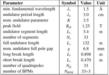
Table 1: LCLS undulator parameters
Parameter Symbol Value Unit
min. fundamental wavelength λr 1.5 Å undulator period length λu 3.0 cm nom. undulator parameter K 3.5
peak field Bpk 1.25 T
undulator segment length Ls 3.4 m
number of segments Ns 33
full undulator length Ls 132 m nom. undulator full pole gap g 6.8 mm long break length Ll 0.898 m short break length Ls 0.470 m
number of quadrupoles NQ 33
number of BPMs NBPM 33+3
INTRODUCTION
The undulator system for the Linac Coherent Light Source (LCLS), under construction at the Stanford Linear Accelerator Center (SLAC), is comprised of 33 identical 3.4-m-long undulator segments, separated from each other by short and long breaks. Every third break is long. The
* Work by U.S. Department of Energy contract DE-AC02-76SF00515 # [email protected]
space provided by these breaks is used to place devices for controlling and monitoring the electron beam. A parameter summary is given in Table 1.
COMPONENT DESCRIPTION
The components relevant to the SASE (self-amplified spontaneous emission) lasing process in the LCLS undulator system include
• Undulator Segments • Segment Slide Supports • Quadrupoles
• Beam Position Monitor (BPM) System • Girder Motion Supports
• Beam Finder Wire (BFW) Devices • Fixed Girder Supports
• Vacuum chamber
• Alignment Diagnostic System (ADS) Sensors • Temperature Sensors
• Air Temperature Stabilization
A brief description for each of these components is provided in this section
Undulator Segments
The undulator segments [1] are fixed-gap permanent magnet planar undulators with a period length of 3 cm and a nominal K value of about 3.5, and are mounted inside a 3.4-m-long Ti strongback of circular cross section. The undulator gap is arranged such that the electron wiggle motion is in the horizontal plane. The upper and lower pole face planes are canted with respect to each other by an angle of 4.5-mrad, which makes the K
value dependent on the electron beam’s horizontal position in addition to its dependence on the vertical position for the regular planar undulator. Each undulator will be operated at a different effective K value to compensate for energy losses during the radiation process and to optimize the SASE process. The magnetic axis, i.e., the ideal average beam trajectory, through the undulator segment will be determined during the tuning of the device and fiducialized to tooling balls on the device body. Undulator magnet tuning will be done in the Magnet Measurement Facility (MMF), which has been specially built for this purpose.
Segment Slide Supports
Each undulator segment is mounted on two parallel horizontal slides that allow remotely controlled repositioning of the segment relative to the electron beam and a full translation to a ‘removed’ position at 8 cm.
September 2006
Invited talk presented at 28th International Free Electron Laser Conference (FEL 2006), 8/27/2006-9/1/2006, Berlin, Germany
Quadrupoles
The quadruple magnets in the LCLS undulator system are arranged in a FODO lattice. They are designed to operate with an integrated quadrupole field gradient of 3 T over the entire LCLS operational energy range between 4.3 GeV to 13.6 GeV. Each quadrupole magnet has dipole correction coils integrated into its design to provide independently controllable horizontal and vertical dipole fields superimposed on the quadrupole fields.
The quadrupole magnets are based on electromagnetic technology, each with its own power supply, and their integrated gradient can be changed in the range between 0 T and 4 T. By varying the gradient, the quadrupoles can be used to measure the transverse distance of the electron beam trajectory from the magnetic center of the quadrupoles, which is fiducialized to the magnetic center of the upstream undulator segment. This enables control of the alignment of the electron beam to the magnetic axis of the undulator segment at its down stream end, where the quadrupole magnet is located. The electromagnetic technology also provides the options of modifying the focusing optics.
Beam Position Monitor (BPM) System
The electron beam position monitor system uses RF cavity BPMs. It has been demonstrated that this type of BPM can provide relative beam position information at better than 1 µm resolution in the 0.2-1 nC charge range, at which the LCLS electron bunches will be operated. Their circular cavity body, machined to have a well-defined mechanical center, will be used in the alignment of this component. One BPM is located just downstream of each quadrupole magnet. An additional 3 BPMs of the same type are mounted upstream of the first segment to monitor the horizontal and vertical launch position and angle of the electron beam.
Girder Motion Supports
Each undulator segment and its beamline components are mounted on a remotely moveable support structure, called a girder [2]. The remote motion is controlled through cam shafts [3] and allows changing the horizontal and vertical position as well as yaw, pitch, and roll of the girders. The components mounted on each of the 33 identical girders include an upstream Beam Finder Wire (BFW) device, two horizontal slides supporting one undulator segment, a downstream quadrupole magnet, an RF cavity BPM, and a Cerenkov radiation detector, as well as the supports for the vacuum chamber throughout the girder, and the mounting plates for the Alignment Diagnostic System (ADS) sensors. The BFW device, the undulator segment, and the quadrupole are fiducialized in the MMF. The complete girder assembly will initially be aligned on the Coordinate Measurement Machine (CMM), which has been specially designed for that purpose. The undulator segment is mountable on and removable from the girder with the vacuum chamber in place and without compromising the alignment of the vacuum chamber. Segments will be swapped on the girder for magnetic
measurements and will be interchangeable without the need for renewed CMM alignment.
Beam Finder Wire (BFW) Devices
The BFW device is a special wire scanner [4], with only two positions for the horizontal and vertical wire pair: the wires will be either in a well reproducible “in”-position, in which they can be brought in collision with the electron beam, or they will be in a “park”-position, where they won’t affect the electron beam. The locations of the wires in the “in” position will be fiducialized to tooling balls mounted on the device body.
Each BFW device enables control of the alignment of the electron beam at its up-stream end. After all quadrupoles are aligned using BBA (see below), the girder can then be moved to bring the wires of the BFW device into collision with the beam, which will complete the alignment of the undulator segments relative to the beam axis. The BFW device will provide a means to accomplish a beam-based undulator segment alignment from the control room without the need for tunnel access. The BFW device is only needed for occasional verifications. The alignment can be achieved at even tighter tolerance levels using portable Hydrostatic Leveling System (portable HLS) and portable Wire Position Monitor (portable WPM) devices without the need for the electron beam to be present [5]. The use of these devices requires, however, extended tunnel access and will be used prior to thebeam–basedcommissioning process. It is expected that the ADS (see below) will be used to monitor the girder positions from then on.
Although not their primary purpose, the BFW wires will also provide transverse beam profile and rms size information. This functionality will be preserved as long as the wire diameter is not larger than about twice the rms beam width. With an rms beam width of 36 µm, a maximum wire diameter of 40 µm is a reasonable upper limit and the choice of a Carbon wire will adequately limit beam loss on the downstream undulators [6]. The transverse position of the wires will be monitored with the cam mover readback system and also, at sub-micron resolution but at a slower rate, with the ADS. Local BPMs can also be used to measure and compensate for any shot-by-shot trajectory jitter during the scan.
Fixed Girder Supports
Each girder is supported by two thermally isolated, sand-filled pillars, with manual adjustments at the top (Figure 4), which allow pre-alignment of the cam movers.
Vacuum chamber
The vacuum chamber of the LCLS undulator system has a 5 mm×12.5 mm rectangular inner cross section through the undulator segments and circular (both 8 mm and 10 mm diameter) cross sections in the breaks. The interaction of the electron beam with the vacuum chamber generates longitudinal and transverse wakefields. The amplitude of the latter is limited by keeping the beam at the center of the chamber with a ±200 µm tolerance. The
vacuum chamber will not be moved when the undulator segment is horizontally repositioned on the slides.
Alignment Diagnostic System (ADS) Sensors
The alignment of the girders will be continuously monitored by the ADS, which is a combination of a Wire Position Monitor (WPM) system and a Hydrostatic Leveling System (HLS), both permanently installed. There are four sensors for each of the two subsystems mounted on each girder, two each close to either end of the undulator segment. The sensors are supported by a mounting plate. The HLS is most sensitive to vertical positioning, while the WPM is best for horizontal positioning.
Temperature Sensors
The temperature will be monitored at several control points on girder components, at girder supports, and at the mounting plates of the ADS sensors.
Air Temperature Stabilization
The temperature of the LCLS undulator tunnel is controlled by a constantly flowing, thermally regulated, air stream [7]. The air enters upstream of the first girder and is blown through the 170-m-long tunnel in downstream direction. Temperature monitoring is done at the entrance point. As the air travels through the tunnel it is expected to pickup heat from the tunnel equipment at a rate of less than 50 W/m. The system is designed such that the air temperature will stay in the range of 19.5º C-20.5º C at all times along the entire undulator system. The undulator K value has been measured to change by 0.015% over a temperature range of 0.28º C.
TOLERANCES AND ALIGNMENT
STRATEGY OVERVIEW
The purpose of the undulator system is to enable the SASE process, which is based on the interaction between an electron bunch and its spontaneous undulator radiation. For obtaining and maintaining high gain in the SASE process, it is important that the electron bunch is in good overlap with the radiation field and that the individual electrons maintain a well defined phase relationship with that field. The radiation field is initially produced in the first undulator segment and will proceed in a straight line, while the electron beam trajectory will deviate from a straight line in the presence of magnetic and electric fields. The ideal undulator magnetic field will generate tiny periodic deviations from the straight line, which are necessary for the SASE process; the first and second field integrals over each undulator segment are ideally zero. Problems arise from off-axis fields of misaligned quadrupoles and undulator segments, the earth’s magnetic field [8], other environmental fields, as well as from errors in the undulator fields that create finite field integrals or increase the electrons’ path lengths through the undulator. The primary mitigation tool includes tuning [9], (for undulator field errors and earth’s magnetic
field), and shielding, (for environmental fields as well as earth’s magnetic field).
The remaining error-fields (off-axis fields in quadrupoles and undulator segments, remnants of undulator field errors, the earth’s magnetic field, and the environmental field) will be corrected through beam based alignment, which compensates the net effect of these fields by adjusting the transverse positions of the quadrupoles, through girder motion and by adding small dipole correction fields through trim coil adjustments. This process will automatically take the largest error field source, (e.g., misaligned quadrupoles), out of the system by moving the centers of the quadrupole magnets to a
goal position, close to a common straight line. The goal
position will be slightly away from that line, just enough to compensate for other remaining error sources. Thus, the goal position of each quadrupole will be precisely defined through the BBA process, and will be deviating from the electron beam trajectory (beam axis, defined by BBA) by about 20 µm (rms), a calculated number based on error amplitude estimates.
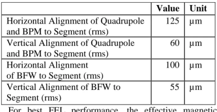
Table 2: Alignment tolerances for component alignment on girders for the LCLS undulator system
Value Unit
Horizontal Alignment of Quadrupole and BPM to Segment (rms)
125 µm Vertical Alignment of Quadrupole
and BPM to Segment (rms) 60 µm Horizontal Alignment of BFW to Segment (rms) 100 µm Vertical Alignment of BFW to Segment (rms) 55 µm For best FEL performance, the effective magnetic centers of all quadrupoles need to be within ±2 µm of their goal position in both the horizontal and vertical directions. Additionally, the magnetic axes of the undulator segments need to be aligned to the beam axis to an accuracy of 140 µm (rms) horizontally and 80 µm (rms) vertically.
Table 3: Alignment tolerances for girder alignment in the LCLS Undulator Hall
Value Unit
Initial rms uncorrelated x/y quadrupole alignment tolerance wrt straight line
125 µm
Longitudinal Girder alignment tolerance
±1 mm Undulator Segment yaw tolerance
(rms)
240 µrad Undulator Segment pitch tolerance
(rms)
80 µrad Undulator Segment roll tolerance
(rms)
1000 µrad
The precise alignment of the quadrupoles can only be achieved using a beam based alignment method (energy scan) while the relative alignment (see Table 2) of the
undulator segments to the quadrupoles and the BFW devices is aided by mounting the components on common, remotely movable girders (see above). The tolerances for the conventional alignment of the girders in the tunnel are reasonably achievable (see Table 3).
ALIGNMENT DIAGNOSTIC SYSTEM
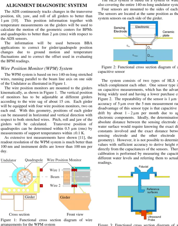
The ADS continuously tracks changes in the transverse position, tilt, yaw, and roll of all girders to better than 1 µm [10]. This position information together with temperature measurements on the girders will be used to calculate the motion of the geometric centers for BPMs and quadrupoles to better than 2 µm (rms) with respect to the ADS sensors.The information will be used between BBA applications to correct for girder/quadrupole position changes due to ground motion and temperature fluctuations and to correct the offset used in evaluating the BPM readings.
Wire Position Monitor (WPM) System
The WPM system is based on two 140-m-long stretched wires, running parallel to the beam line axis on one side of the Undulator as illustrated in Figure 1.
The wire position monitors are mounted to the girders kinematically, as shown in Figure 1. The vertical position of monitors has to be adjustable at different girders according to the wire sag of about 15 cm. Each girder will be equipped with four wire position monitors, two on each end. With this geometry, positions of each girder can be measured in horizontal and vertical direction with respect to both stretched wires. Pitch, roll and jaw of the girders will be calculated. Transverse position of quadrupoles can be determined within 0.5 µm (rms) by measurements of support temperatures within ±0.1 K.
As extensive test measurements have shown [11], the readout resolution of the WPM system is much better than 100 nm and instrument drifts are lower than 100 nm per day.
Undulator Wire Position Monitor
Wire 1 Wire 2 Girder Quadrupole Girder Beam
Cross section Front view
Figure 1: Functional cross section diagram of wire arrangements for the WPM system
Due to the unavoidable large sag of long wires, the uncertainty of the wires in vertical direction will be higher than one micrometer, which is the required design
objective for the quadrupoles. Therefore, the vertical position of both wires will be correlated to the horizontal plain defined by the Hydrostatic Leveling System.
Hydrostatic Leveling System (HLS)
The HLS system is based on a system of water pipes also covering the entire 140-m-long undulator system.
Four sensors are mounted to the sides of each girder. The sensors are located at the same position as the WPM system sensors on each side of the girder.
Figure 2: Functional cross section diagram of an HLS capacitive sensor
The system consists of two types of HLS sensors, which complement each other. One sensor type is based on capacitive measurements, which has the advantage of being widely used and having a lower purchase cost, see Figure 2. The repeatability of the sensor is 1 µm with an accuracy of 5 µm over the 5 mm measurement range. A disadvantage of this sensor type is that capacitive sensors drift by about 1 – 2 µm per month due to aging of electronic components. Ideally, the determination of the absolute distance between the sensing electrode and the water surface would require knowing the exact dielectric constants involved and the exact distance between the sensing electrode and the other electrode (vessel geometry). However, it is not possible to determine these values with sufficient accuracy to derive height readings directly from the capacitances of the sensors. Therefore, a calibration is performed by measuring the capacitance at different water levels and referring them to actual height readings.
Figure 3: Functional cross section diagram of an HLS ultrasound sensor.
The second type of sensor is based on ultrasonic runtime measurements, see Figure 3. The measurements
are self calibrating and therefore no drifts are expected. The repeatability of the sensor is 1 µm with an accuracy of 5 µm over the 5 mm measurement range. The ultrasound sensors measure the runtime to the two reference surfaces of the probe and to the water surface. This provides information about the water level with respect to the external fiducial of the probe. The ultrasound sensors, once mounted to the girder, are measured with the CMM. They are used to set the height of the girder in the tunnel during the conventional alignment step. Since the ultrasound sensors provide actual height differences to the water surface they can be used to calibrate the capacitive sensors.
MONITORING ELEMENTS SUMMARY
Monitoring elements are used to detect girder position as well as electron beam position. The following list provides a summary:• Hydrostatic Leveling System (HLS) o monitors y, pitch, and roll
• Wire Position Monitoring System (WPM) [11] o monitors x, (y), (pitch), yaw, and roll • Temperature Sensors
o in support of HLS/WPM readout corrections, undulator K corrections, and component motion interpretation
• Beam Position Monitors*
o monitors x and y positions of the electron beam • Quadrupoles*
o can be used to measure x and y offsets of the electron beam with respect to the quadrupole center
ALIGNMENT CONTROLS
A number of manual (local) and remote adjustments are available for the alignment of the beamline components of the LCLS undulator system.
Figure 4: Undulator segment supports
Local Controls
Alignment of the cam supports is done using the manual adjustment controls on top of the support
*
Transverse Locations Tracked by HLS and WPM
pedestals (see Figure 4). Relative alignment of girder components to the magnetic axes of the undulator segments (on the CMM) is done by using the manual adjustable supports of the quadrupole, BPM and BFW components, which provide a range of ±2 mm in the horizontal and vertical directions with a resolution of 2 µm. The height of the magnetic axes of the undulator segments above the segment supports is controlled by permanent shims created specially for the undulator after the tuning process and permanently bolted to its bottom. This makes all undulator segments interchangeable with each other.
Remote Controls
The transverse positions of the girders are (remotely) controlled based on cam mover technology
• during initial conventional alignment (see above) • for quadrupole position control, i.e., beam steering
during BBA. • for BFW scans
• for compensation of ground motion effects etc. The motion range is such that each quadrupole magnet can be moved ±0.7 mm in any transverse direction from its neutral position. The motion control allows moving a single quadrupole independently in the horizontal and vertical direction without affecting the adjacent quadrupoles and without introducing roll to the girder assembly. All girder components will be moved together when a quadrupole is repositioned so that the BFW device, the undulator segment, the quadrupole, the BPM and the vacuum chamber will stay aligned relative to each other. The horizontal position of the undulator segment is remotely controlled for
• field strength adjustment (change of K)
• reduction of radiation exposure during commissioning (full roll-out position),
• measurement of FEL gain as function of z (full roll-out position),
• measurement of K using spontaneous radiation from only two adjacent, interfering undulators [12].
CONVENTIONAL ALIGNMENT
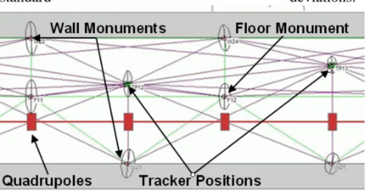
The conventional alignment of the undulator system focuses on bringing the quadrupole magnets into a straight line at tolerances specified in Table 3.To achieve this goal, the first step is to establish a monument network inside the undulator hall. This set of coordinates assigned to the network points serves as the representation of the coordinate system and is the basis for all component set-ups. In practice, the points are nests compatible with 1.5" spherical tooling. They can be equipped with SMRs (Spherically Mounted Retroreflectors) for laser tracker observations, or solid sphere based rods for leveling observations. Simulations have been made with a regular pattern of both floor and wall targets. Figure 5, below, represents the middle section of the undulator hall with the red rectangles representing quadrupoles. A floor point is installed in the
middle of the tunnel at every other quadrupole location. The laser tracker positions are placed in front of the other quadrupoles with a staggered offset from the beamline. The tracker observations (purple lines) have a-priori standard deviations based on recent experiences and standard observation practices: 30 µm for the distances and an inverse function of the distance for the two angles (30 µm and 50 µm at one meter for the horizontal and the vertical, respectively). The weight of the leveling observations (green lines) is based on 50 µm as a-priori
standard deviations.
Figure 5: The undulator hall network, used in Simulation, is shown relative to quadrupole locations. Floor and wall monuments as well as tracker positions are shown. The largest semi-major axis of the error ellipses is below 50 µm.
Figure 5 shows the resulting error ellipse at 1 sigma for a free-net approach. All semi-major axes are below 50 µm. This free-net approach assumes that the location and orientation of the LCLS undulator coordinate system [13] has been established through the inclusion of a number of points known in the SLAC linac system.
Once the network is established, the points can be used for the markings on the floor, the alignment of the fixed support pillars and finally the pre-alignment of the girders. For all these tasks, total station set-ups are performed. A solid resection of the instrument, based on at least two floor monuments and three wall monuments, can guarantee the necessary requirement for point determination. Depending on the duration of the installation and the characteristics of the floor curing, an additional survey of the monument network will be observed to control and update the coordinates.
After the undulator segments are installed, a final mapping of all monuments and all fiducials is performed. The scenario for the laser tracker position and methodology is identical to the one used to derive the monument network. The fiducials of the girders, undulator segments, quadrupoles, BFW devices and HLS ultrasound sensors are observed from multiple laser tracker stations. Leveling observations between monuments and selected fiducials are added. The adjustment of all observations is again performed with a free-net approach. Finally the measurements with the laser tracker and the digital level are combined with the portable HLS and WPM observations. If moves are
required, they can be checked by the ADS readings and do not require a full remapping of the undulator hall.
BEAM-BASED ALIGNMENT
The electron beam trajectory through the FEL undulator must be straight to a level of about 2 µm over one FEL gain length (~5 m). This level is difficult to achieve using standard component survey methods, and therefore requires a special electron Beam-Based-Alignment (BBA) algorithm [5] which samples undulator BPM readings at three different beam energies (13.6, 6.5, and 4.3 GeV). Changing the linac energy will require a change in many magnetic components upstream of the first undulator to keep the beam matched to the undulator optics, and to keep the horizontal and vertical position and angle of the trajectory at the entrance to the undulator independent of energy. The latter will be monitored by a set of three RF cavity BPMs located between the last quadrupole of the linac-to-undulator beam transport line and the first undulator segment. Detailed simulations have been made, which indicate that adequate beam-based alignment can be achieved if undulator quality and beam stability are within the tight tolerance specifications described here.
BBA will use quad motion and dipole trims for beam corrections. The BBA algorithm uses the off-axis field in the quadrupoles for trajectory correction. Changes are applied through cam-based girder motion, which will automatically align the quadrupoles in the process. Thus, the main source of the original trajectory errors, i.e., quadrupole misalignment, will be taken out by BBA. Secondary sources, such as undulator field errors, the earth’s magnetic fields, and other environmental fields are expected to be small and will require slight off-center positioning of the quadrupoles to generate the required correction field on beam axis. The largest of these corrections can then be partially taken over by dipole trim correctors, which are integrated in the quadrupole design. Their range is equivalent to ±100 µm of quadrupole motion. The BPMs must have a relative position measurement resolution of <2 µm rms in order to achieve trajectory straightness adequate to support 1.5-Å FEL operations. This resolution definition implies that the BPM readback offsets (electrical or mechanical) must be stable to <2 µm over the one hour required to accumulate the BBA data.
TOLERANCE ZONES
A systematic plan for trajectory correction during operation has been developed based on tolerance zones and different levels of correction. This plan integrates the results of global tolerance studies, which predict an amount of FEL power loss as a function of the size of the errors, with a sequence of correction operations with increasing disruption to the FEL beam. Starting at the completion of a full BBA session, there will be continuous trajectory feedback systems running at 120 Hz, based on LTU (Linac-To-Undulator transport line) BPMs, and at 0.1 Hz, based on undulator BPMs,
which are tracked by the ADS (Zone 1). Every few hours (Zone 2) small girder position corrections, based on ADS measurements, will keep the quadrupoles at their goal
positions to restore most, but not all, of the beam power which is expected to sag by up to 10%. This can be done without disruption of the FEL beam. Once a day (Zone 3), re-adjustment of the FEL beam pointing direction may be done. Once a week or less (Zone 4), a full BBA session will be used to get back to the original tolerance zone, which will interrupt FEL beam delivery for less than an hour. Before the BBA is applied, the FEL power level is expected to drop by no more than 25%. Full BBA should fully restore the FEL power to the original level. At an interval of roughly once every six months (Zone 5), a cam mover may range-limit and a planned access will be used to reset cam blocks as necessary.
ALIGNMENT FUNCTION DIAGRAM
The main function block of the undulator alignment system is given in Figure 6. Alignment functions are performed in the Magnet Measurement Facility (MMF) and in the Undulator Hall (UH). Alignment tasks performed in the MMF include the tuning and fiducialization of the undulator segments as well as the fiducialization of the quadrupoles and the BFW devices. The components are then mounted on the girder and aligned. The alignment is checked on the CMM, which is also located in the MMF. The undulator segments are stored separately from the girders until they are installed in the UH. In preparation for the girder installation, fixed support pillars are installed in the UH and aligned. The girders are then installed and pre-aligned on the fixed support pillars after the environmental magnetic field has been measured and recorded along the entire undulator line. After installation of the ADS system, the continuousmeasurement and recording of the girder positions will start. The undulator segments are then mounted onto the horizontal slides on top of the girders, and the quadrupoles are aligned onto a straight line with conventional alignment. Then, portable WPM and HLS systems [14] will be used for a precise alignment of the undulator segments between neighboring quadrupole magnets.
Every few hours small girder position corrections based on ADS measurements will keep the quadrupoles at their goal position (which will be reset after BBA) to better than ±2 µm over a 1-hour period and to better than ±5 µm over a 24-hour period, in order to support BBA. The next alignment steps involve the electron beam. BBA based on BPMs and quadrupoles under observation of the ADS will be used to straighten the electron beam trajectory to the level required to achieve FEL gain. At this point, continuous position corrections based on BPM readings will start. The BPM readings will be corrected for any device motion, as reported by the ADS.
The BFW devices can now be used to check the alignment of the upstream end (‘loose end’) of the undulator segments.
Every 2-4 weeks, the procedure loops back to BBA (one iteration, rather than the initial three, may be sufficient), which requires interrupting beam delivery.
Once per month, three undulator segments will be swapped out of the tunnel and brought back to the MMF to be checked for detuning effects, such as radiation damage. At the same time, three of the six replacement undulator segments, which will have been prepared ahead of time, will be installed in the empty slots. As mentioned above, the undulator magnets are mechanically shimmed that the magnetic axis will come to lie in the same x, y
location when placed onto a given girder. Every six months, when cam movers might have run out of range Figure 6: Alignment Function Diagram
due to the expected continuous ground motion, there will be a maintenance shutdown for re-baselining, i.e., realignment of the cam movers using the manual adjustments on top of the support pillars.
SUMMARY
The X-ray FEL demands very tight tolerances on magnetic field quality, electron beam straightness, and undulator segment alignment. These tolerances can be achieved through BBA procedures based on BPMs and quadrupoles (with energy scan) as well as BFW devices.
Relative component alignment to the required tolerances will be achieved through common girder mounting. Main tasks of the conventional alignment and motion systems are:
• Component fiducialization and alignment on girder • Conventional alignment of girders in Undulator
Hall as prerequisite for BBA.
The ADS measures and enables the correction of girder movement due to ground motion, temperature changes, and cam mover changes. A strategy is in place for using the monitor systems and the controls in order to establish and maintain a straight FEL trajectory.
ACKNOWLEDGEMENTS
It is a pleasure to acknowledge contributions by Argonne National Laboratory’s LCLS team.
REFERENCES
[1] I. Vasserman, R. Dejus, P. Den Hartog, E. Moog, S. Sasaki, E. Trakhtenberg, and M. White, "LCLS Undulator Design Development." FEL2004 Proceeding, 2004.
[2] E. Trakhtenberg, J. Collins, P. Den Hartog, and M. White, "Design of a Prototype Precision Positioning System for the Undulators of the Linac Coherent Light Source." PAC2005 Proceedings, 2005.
[3] G. Bowden, P. Holik, S.R. Wagner, G. Heimlinger, and R. Settles, "Precision Magnet Movers for the Final Focus Test Beam." SLAC-PUB-95-6132, 1995. [4] J. Wu, P. Emma and R.C. Field, "Preliminary Study
on Electron Signal Detection for the Beam Finder Wire of the LCLS Undulator." LCLS-TN-06-7, 2006.
[5] P. Emma, H.-D. Nuhn, and R. Carr, "Beam Based Alignment for the LCLS FEL Undulator." Nucl. Instrum. Meth. A429:407-413, 1999.
[6] J. Welch, "Estimate of Undulator Magnet Damage Due to Beam Finder Wire Measurements."
LCLS-TN-06-6, 2006.
[7] J. Welch, "Air Temperature in the Undulator Hall."
LCLS-TN-06-2, 2006.
[8] K. Hacker, Z. Wolf, "Earth's Magnetic Field Measurements for the LCLS Undulators." LCLS-TN-05-4 , 2005.
[9] Z. Wolf, "Introduction to LCLS Undulator Tuning."
SLAC-TN-05-043, 2004.
[10] J. Welch, "Ground Motion Expectations for the LCLS Undulator Hall." SLAC-TN-05-013,
LCLS-TN-04-14, 2004.
[11] F. Peters, G. Gassner, and R. Ruland, "First Measurements and Results With a Stretched Wire Test Setup." LCLS-TN-05-7, 2005.
[12] J. Welch, et al., these FEL’06 proceedings.
[13] E. Bong, P. Emma, C. LeCocq, T. Montagne, and J. Welch, "LCLS Undulator Coordinate System."
SLAC-TN-05-021, LCLS TN-03-8, 2004.
[14] G. Gassner, "Proposal for the Alignment of the ‘Loose End’." LCLS-TN-06-11, 2006.