47 Malaysian Journal of Computer Science, Vol. 32(1), 2019
ACCELERATING FPGA-SURF FEATURE DETECTION MODULE BY MEMORY ACCESS REDUCTION
Mohd. Yamani Idna Idris1, Nor Bakiah Abd. Warif2, Hamzah Arof3,
Noorzaily Mohamed Noor4, Ainuddin Wahid Abdul Wahab5, Zaidi Razak6
1,2,4,5,6 C4MCCR, Faculty of Computer Science & Information Technology, University of Malaya, Kuala Lumpur, Malaysia
2Faculty of Computer Systems & Software Engineering, Universiti Malaysia Pahang, Malaysia
3Faculty of Engineering (Electrical), University of Malaya, Kuala Lumpur, Malaysia
Email: [email protected] (corresponding author), [email protected]2/[email protected]2, [email protected], [email protected]4, [email protected]5, [email protected]6
DOI: https://doi.org/10.22452/mjcs.vol32no1.4
ABSTRACT
Feature detection is an important concept in the area of image processing to compute image abstractions of image information, which is used for image recognition and many other applications. One of the popular algorithm used is called the Speeded-Up Robust Features (SURF), which realized the scale space pyramid to detect the features. For this reason, prior researchers concentrate on applying parallelism onto the SURF multiple layers using technology such as Field Programmable Gate Array (FPGA). However, prior FPGA-SURF implementation does not emphasis on memory access limitation that can affect the overall performance of a system. This paper proposes a study on FPGA-SURF and memory access implementation in feature detection area. We conduct a profiling test and founds that the external memory access to fetch the integral image data in SURF highly affects the overall performance. We also found that the SURF algorithm memory access has redundant repeating pattern that can be reduced. Therefore, a controller design that stores repeating data (for the subsequent process) in an on-chip memory is proposed. This method reduces the external memory access and can increase the overall performance. The result shows that our proposed method improves the existing method (i.e. without the memory access reduction) by 1.23 times when the external memory latency is 20ns.
Keywords: SURF, FPGA, Feature Detection, Memory Access, Fast Hessian 1.0 INTRODUCTION
The initial step in many image processing applications is to detect distinct feature of an image. Feature detection is a method used to identify the presence of distinctive characteristics in an image. The characteristics can be identified by locating the unusual activities or statistics variation between certain regions and their background. In Simultaneous Localization and Mapping (SLAM) for example, feature detection is used to find the interesting part of an image that would differentiate the landmark and the less important image details. This landmark is further processed to build a map of an environment and at the same time compute location. The feature detection step is important since it is the starting point to determine the functionality of the overall algorithm. For that reason, various number of feature detection algorithms have been studied and developed [1].
While most feature detection algorithms in SLAM are implemented for online processing, many researchers have turned to the on-chip solutions such as Field Programmable Gate Array (FPGA) to meet the fast processing requirement. Although FPGA run slower than most CPUs, the ability to be programmed with pipelining and parallel architecture has made FPGA a suitable candidate to increase program performance [2][3][4]. This is because, software based implementation on a general purpose CPU may have to conduct hundreds of clock cycles and multiple instructions to do similar thing. For this reason, the review on the earlier research related to the feature detection implementation using FPGA is presented. The review will give attention to the eminent feature detection algorithms such as Harris, Tomasi-Kanadi, SUSAN, SIFT and SURF. From the review, SURF shows significant advantage over
48 Malaysian Journal of Computer Science, Vol. 32(1), 2019
others. Therefore, we have chosen SURF algorithm to be further investigated. The investigation shows that the earlier researchers choose the SURF because the multiple layer of the scale space pyramid in the SURF algorithm can be processed in parallel. Though typical FPGA-SURF can improve software based approach, more efficient method is needed for real time processing especially for larger data input. Large data input is an important component to increase the overall feature detection accuracy. In this paper, a software profiling tool is utilized to improve prior FPGA-SURF implementation further. The profiling will determine the slowest program section that affects the overall SURF algorithm performance. Based on the profiling result, a new design will be proposed to improve the prior FPGA-SURF implementation.
2.0 RELATED WORK
The research to determine the specific characteristic that can differentiate image of interest and their background has been given close attentions by image processing researchers. This is due the importance of feature detection technique to ensure the reliability of the results. One of the earliest and widely used feature detection techniques is called Harris corner detector [5]. Harris corner detector improves prior Moravec [6] implementation by combining corner and edge detector based on the local auto-correlation function. Although Harris corner detector performs with good consistency on natural imagery, it is not scale-invariant. For that reason, Lindenberg [7][8] has studied the scale invariant problem and has proposed systematic methodology to select local appropriate scales which can be used for automatic scale selection. In 2002, Mikolajczyk et al. [9] uses Lindenberg’s fundamental idea to introduce Harris-Affine approach. They show that Harris-Affine detector significantly improves the results for strong affine deformations compared to the Harris-Affine-Regions [10] and Harris-Laplace [11] approach. The Harris-Affine-Regions approach is a scale Harris detector with affine normalization of the point regions whereas the Harris-Laplace approach is a multi-scale Harris detector with characteristic multi-scale selection.
The FPGA based implementation of the Harris corner detector comes several years later. Researchers used the FPGA based implementation to increase the execution speed as well as to reduce power consumption. Cabani et al. [12] presented FPGA architecture for an affine-invariant feature detector based on the algorithm proposed by Mikolajczyk et al. [13]. Other implementation of Harris corner detector on FPGA can be seen from Tippetts et al. [14] and Hsiao et al. [15]. The Harris corner detector however demands very high computational power. The FPGA approach also has been implemented using Tomasi and Kanade’s [16] corner detector. Benedetti et al. [17] and Bissacco et al. [18] designs FPGA based Tomasi and Kanadi’s corner detector to efficiently track features. Although Tomasi and Kanadi’s corner detector is robust to rotation and translation, it does not perform well when there are changes in the scale of the picture. Claus et al. [19] on the other hand designs FPGA hardware accelerator to speed up “Smallest Univalue Segment Assimilating Nucleus” (SUSAN) algorithm [20]. SUSAN is chosen because of its relatively low computational complexity. Since no multiplications are required, SUSAN is an excellent choice for FPGA implementation. SUSAN is also effective for synthetic images but it does not execute well while used with natural images.
Another well-known feature detection technique is called the Scale-Invariant Feature Transform (SIFT). SIFT is introduced by David Lowe [21][22] to improve the prior feature detection. It transforms image into a large collection of local feature vectors that being largely invariant to changes in scale, illumination, and local affine distortions. To increase the processing speed, Lowe approximated the Laplacian of Gaussian (LoG) through a Difference of Gaussians (DoG) filter. Since then, SIFT has went through several changes and improvement [23]. A FPGA based SIFT detector was proposed in Se et al. [24]. In the research, Se et al. utilized SIFT algorithm for their planetary exploration rovers. SIFT on FPGA is also employed by Barfoot et al. [25] and Chati et al [26]. Though able to improve the prior implementation, SIFT suffers from very high computational power similar to Harris Corner Detector.
Herbert Bay [27] proposed approximation to the Laplacian of Gaussians by using box filter representations of the respective kernels based on SIFT. Their implementation is called the Speeded Up Robust Features (SURF) algorithm. Based on the experiments conducted, SURF shows the ability to outperform David Lowe’s state of the art SIFT and it variants namely PCA SIFT [28] and GLOH [29]. Juan and Gwun [30] compared the performance of SIFT, PCA-SIFT and SURF. They claimed that SURF has a good performance as same as PCA-SIFT, however SURF is not stable to rotation and illumination changes. SURF has been implemented on FPGA to improve the overall execution speed. Svab et al. [31] claim that their FPGA-SURF implementation can achieve about 10 frames per second (fps) at HD (1024x768 pixels) resolution and takes less than 10W total power consumption. Bouris et al. [32] state that their proposed FPGA-SURF implementation outperforms state-of-the-art dual-core Intel CPU by at least 8 times. The proposed implementation can process standard video (640 x 480 pixels) at up to 56 fps and consumes less than 20W.
49 Malaysian Journal of Computer Science, Vol. 32(1), 2019
FPGA-SURF implementation is also implemented by Schaeferling et al. [33], which presented a novel, scalable and flexible architecture for computing robust features to be used in optical tracking applications. Meanwhile, Krajnik et al. [34], presents a standalone FPGA-based embedded module that capable of real-time extraction of SURF from camera images. The module processes approximately ten 1,024 × 768 pixel images per second, consumes approximately 6W of power, and occupies significantly less space than a GPU-based system with a similar performance. Therefore, the FPGA-SURF implementation is claimed to outperform the prior feature detection FPGA implementation. For that reason, SURF is chosen in this paper to be further studied.
3.0 SURF ALGORITHM BACKGROUND
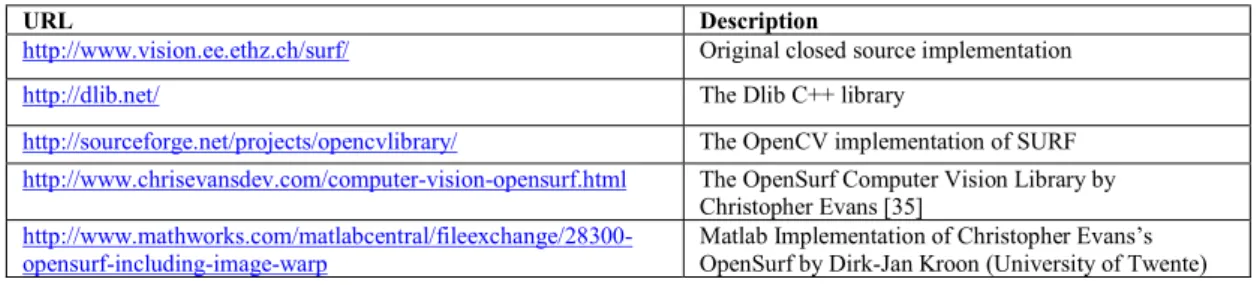
SURF has been widely used by many researchers for their research and applications. Due to its popular demand, open source software implementation of SURF is also available. Table 1shows the list ofthe software implementation of SURF.
Table 1: SURF Algorithm Software Implementation
By using these published available programs and codes, researchers are able to study the SURF implementation. Generally, SURF algorithm can be divided into three stages (i.e. integral image calculation, feature detection, and finding feature descriptor). In the first part, an integral image (I∑) calculation is performed using Eq. (1). In the equation, I represents the image and 𝑥 = (𝑥; 𝑦) is the location of the image pixel. The integral image is used as a rapid and effective way to calculate summations over image sub regions. It is useful later in the computations of Gaussian and Haar wavelet filter to find the SURF descriptor.
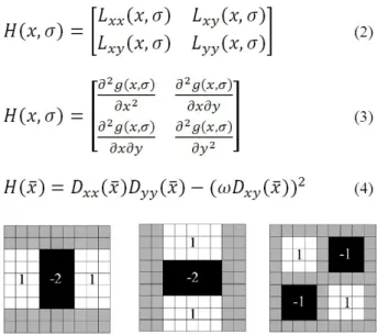
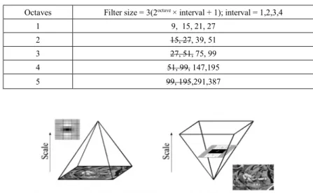
The second step in SURF is to determine a distinct feature using a feature detector. The feature detector is based on the use of the Hessian-matrix approximation, which has good performance in computation time and accuracy. SURF exploits determinants of Hessian matrices to locate image’s important points. Hessian matrix (Eq. (2)) can be calculated as function of both locations 𝑥 = (𝑥; 𝑦) and scale σ using second order Gaussian derivatives known as Laplacian of Gaussian (LOG) (Eq. (3)). However, it is computationally expensive to calculate determinant using exact filters as in Eq. (2) and Eq. (3). Therefore, approximations in terms of box filters Dxx, Dyy and Dxy as in Fig. 1are used in SURF algorithm. The determinants are then calculated using Eq. (4)withparameter ω is used to compensate the approximation error. Bay et al. [27] derives this ω value as equal to 0.912. This detector is now known as Fast-Hessian. The box filters are also used to create scale space which will allow objects under different scales to be recognized. The scale-space is divided into a number of octaves (with each octave has four intervals) and box filter size (Table 2).
URL Description
http://www.vision.ee.ethz.ch/surf/ Original closed source implementation
http://dlib.net/ The Dlib C++ library
http://sourceforge.net/projects/opencvlibrary/ The OpenCV implementation of SURF http://www.chrisevansdev.com/computer-vision-opensurf.html The OpenSurf Computer Vision Library by
Christopher Evans [35]
http://www.mathworks.com/matlabcentral/fileexchange/28300-opensurf-including-image-warp
Matlab Implementation of Christopher Evans’s OpenSurf by Dirk-Jan Kroon (University of Twente)
50 Malaysian Journal of Computer Science, Vol. 32(1), 2019
Fig. 1: Dxx, Dyy and Dxy filters for filter size 9×9 Table 2: Scaling (σ) using scale space
Following the scale space creation, the interest point localization task is performed. In this task, responses that fall below a predetermined threshold are discarded. Non-local maxima suppression is also performed among 26 closest neighbors (i.e. 9 points × 2 (for above and below) + 8 points in native scale) in the determinant scale space. This task is conducted to find a more refined set of candidate interest points. The interest points are further refine to sub-pixel precision using interpolation technique where the determinant of the Hessian function, 𝐻(𝑥; 𝑦; 𝜎) is expressed as a Taylor expansion up to quadratic terms centered at detected location (Eq. (5)). The interpolated location of the extremum 𝑥_ℎ𝑎𝑡 = (𝑥; 𝑦; 𝜎) is established by taking the derivative of Eq. (5) and setting it to zero (Eq. 6). If 𝑥_ℎ𝑎𝑡 > 0.5 in the x, y or σ directions, the location has to be adjusted and the interpolation has to be performed once again until 𝑥_ℎ𝑎𝑡 < 0.5 in all directions or the number of predetermined interpolation steps has been exceeded. This to ensure only the most stable and repeatable set of interest points is available for the upcoming process.
In the third step of SURF, the orientation and descriptor extraction are calculated. The orientation calculation is performed to achieve rotation invariance by assigning each interest point a dominant direction. To do this, Haar wavelet responses of size 4s are calculated for a set of pixels that are located within a radius of 6s around the detected feature. In this case, s refers to the scale of the detected feature. Then, the responses are weighted with a Gaussian function with a standard deviation of 2.5s centered at the detected feature point. The dominant direction is selected using a sliding orientation window which rotates a circle segment covering an angle of 𝜋/3. The longest vector obtained when the two horizontal and vertical responses within the window are summed is chosen to be descriptor dominant direction.
The descriptor is extracted by applying Haar wavelets to the pixels within a square window of size 20s centered on the interest point, and oriented along the orientation selected in the prior step. The window is further divided into
Octave 1 5 Interval 1 2 3 4 1 2 3 4 Filter Size = 3(2octave × interval + 1) 9 15 21 27 99 195 291 387 σ = Filter Size × = Filter Size × . 1.2 2 2.8 3.6 13.2 26 38.8 51.6
51 Malaysian Journal of Computer Science, Vol. 32(1), 2019
smaller 4 × 4 square sub-regions to keep important spatial information. For each sub-region, a few simple features at 5 × 5 regularly spaced sample points are computed using Haar wavelet of size 2s. Each sub-region contributes a 4-dimensional vector 𝑣 = (∑𝑑𝑥, ∑𝑑𝑦, ∑|𝑑𝑥|, ∑|𝑑𝑦|)to form 64 dimensional SURF descriptor.
4.0 SURF ALGORITHM SOFTWARE PROFILING AND ANALYSIS
In this paper, an open source OpenSURF implementation and a software profiling tool is utilized to determine the section with the heaviest processing time. Fig. 2shows SURF algorithm software profiling result. In the figure, it can be seen that IntegralImage_BoxIntegral has the highest self-time. The IntegralImage_BoxIntegral is a function within the feature detection stage where the determinant of the Hessian matrices or Fast-Hessian is calculated. It is used to compute response component of Dxx, Dyy and Dxy. This function is called many times depending on how many octaves are chosen. For example, if the number of octaves is 5, there will be 20 iterative processes (i.e. for filter size 9, 15, 21, 27, 15, 27, 39,….291, 387) to extract responses from an image. Since certain octaves use equivalent filter with the same size, the iterative process can be reduced to 12 (Table 3). Therefore, in a typical sequential software implementation, the process will have to wait and repeats 12 times. To reduce the waiting time, researchers shifted to FPGA based implementation in order to process data in parallel. The motivation for such implementation comes from the nature of the SURF algorithm that allows multiple layers of the scale-space pyramid to be processed simultaneously and discards the need to subsample the image. In a prior implementation like SIFT, each layer relies on the previous layer where the input image is iteratively convolved with Gaussian kernel and repeatedly sub-sampled (Fig. 3). Thus, it is not easy for such typical implementation to utilize parallelism. For this reason, FPGA-SURF related works conducted by prior researchers such as Svab et al. [31], Bouris et al. [32] and Schaeferling et al. [33] concentrate on performing box filters parallel calculation at variable scale levels.
Fig. 2: Software profiling result of the SURF algorithm
Table 3: Octaves and its filter size (equivalent filter with the same size can be removed (i.e. the number with strikethrough))
Octaves Filter size = 3(2octave × interval + 1); interval = 1,2,3,4
1 9, 15, 21, 27
2 15, 27, 39, 51
3 27, 51, 75, 99
4 51, 99, 147,195
5 99, 195,291,387
52 Malaysian Journal of Computer Science, Vol. 32(1), 2019
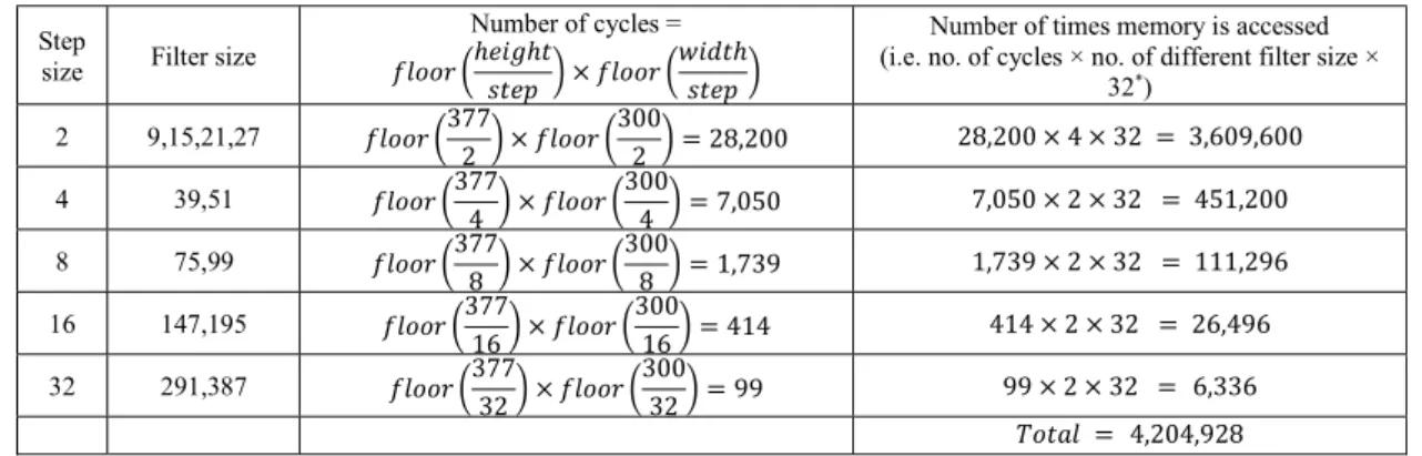
Though prior FPGA-SURF implementation concentrates on designing FPGA architecture to process multiple layers of the scale-space pyramid in parallel, the most time consuming part of the SURF program has not been highlighted. Hence, we take additional efforts to examine the slowest section of the SURF program by carefully study the IntegralImage_BoxIntegral function as shown in Fig. 4. From the observation, it can be seen that one of the reasons for the slow processing time is the need of the IntegralImage_BoxIntegral function to access memory to fetch integral image data (i.e. iimg). The calculation of Dxx and Dyy takes 8 memory accesses each, while the calculation of Dxy needs 16. Altogether, the memory needs to be accessed 32 times (i.e 8+8+16 from Dxx, Dyy and Dxy) for each round. The cycles needed for accessing memory depend on the value of initial sample, filter size and the image size. Table 4 shows the calculation on how many times the memory is accessed when initial sample = 2 and image size =377 × 300. From table 4, it can be seen that the total memory access for the example is equal to 4,204,928 times. This indicates that a single port RAM with one data input and one data output would have to wait for a total number of 4,204,928 cycles to complete the process. Based on this example, it can be said that although the address calculation can be computed in parallel, memory access can be a limiting factor to the performance increase. For this reason, the address allocation for the memory access is studied.
An example of the address generation output to access the integral image data for filter = 9 is shown in Appendix 1. The calculation is based on the generation of arrays for N-D functions and interpolation (i.e. ndgrid) which has constant values. A deeper look at the generated address shows that several values are repeating or redundant in other rounds. In Appendix 1 for example, the values of ADxx1 at row number 3 to the end (i.e. -756,-2,752,1506……, (upward diagonal shaded)) are values that are repeated form the values of ADxx2 at row number 1 to the end. This is also true for BDxx1 & BDxx2, CDxx1 & CDxx2, DDxx1 & DDxx2, ADxy1 & ADxy3, BDxy1 & BDxy3, CDxy1 & CDxy3, DDxy1 & DDxy3, ADxy2 & ADxy4, BDxy2 & BDxy4, CDxy2 & CDxy4, and DDxy2 & DDxy4. In a typical implementation, memory needs to be accessed 902,400 (i.e. 28,200 rounds × 32 data) times when filter = 9 (Table 4). However, this number can be reduced to 32 + 30 + 20 × (28,200 − 2) = 564,022 times if the repetitive address is discarded from accessing the external RAM. The number 564,022 is obtained from 32 data of the first round (i.e. first row), 30 data from the second round/row (i.e. BDxx2 and DDxx2 (i.e. addr 6 & 8) are not included since they are repeated values from BDxx1 and DDxx1 (i.e. addr 2 & 4)), and 20 data for the subsequent rounds (i.e. ADxx1, CDxx1, BDxx2, DDxx2, ADxy2, BDxy2, CDxy2, DDxy2, ADxy3, BDxy3, CDxy3, DDxy3 (i.e. addr 2,4,5,7,17,18,19,20,29,30,31,32) are repeated values from prior addresses).
Further studies on the address generation for other filter size also shows repeating and redundant pattern. However, the access pattern for other filter size is slightly different. Appendix 2shows the address generation result when the filter size is 15 pixels. From the appendix, it can be observed that the second and fourth column starts to repeat after the second round and another 10 more addresses repeats after the third round. Therefore, the total memory access for filter size = 15 can be reduced to 564,034. The remaining address generation for other filter size is also observed. Based on the observation, the number of memory access considering maximum of 4 rounds buffering is summarized in Table 5. In comparison, the proposed approach is able to reduce the memory access to 4,204,928/2,814,336 = 1.4941 times.
Table 4: Example calculation on number of times memory is accessed when initial sample = 2 and image size = 𝟑𝟕𝟕 × 𝟑𝟎𝟎
Step
size Filter size
Number of cycles = 𝑓𝑙𝑜𝑜𝑟 ℎ𝑒𝑖𝑔ℎ𝑡
𝑠𝑡𝑒𝑝 × 𝑓𝑙𝑜𝑜𝑟
𝑤𝑖𝑑𝑡ℎ 𝑠𝑡𝑒𝑝
Number of times memory is accessed (i.e. no. of cycles × no. of different filter size ×
32*) 2 9,15,21,27 𝑓𝑙𝑜𝑜𝑟 377 2 × 𝑓𝑙𝑜𝑜𝑟 300 2 = 28,200 28,200 × 4 × 32 = 3,609,600 4 39,51 𝑓𝑙𝑜𝑜𝑟 377 4 × 𝑓𝑙𝑜𝑜𝑟 300 4 = 7,050 7,050 × 2 × 32 = 451,200 8 75,99 𝑓𝑙𝑜𝑜𝑟 377 8 × 𝑓𝑙𝑜𝑜𝑟 300 8 = 1,739 1,739 × 2 × 32 = 111,296 16 147,195 𝑓𝑙𝑜𝑜𝑟 377 16 × 𝑓𝑙𝑜𝑜𝑟 300 16 = 414 414 × 2 × 32 = 26,496 32 291,387 𝑓𝑙𝑜𝑜𝑟 377 32 × 𝑓𝑙𝑜𝑜𝑟 300 32 = 99 99 × 2 × 32 =
6,336
𝑇𝑜𝑡𝑎𝑙 = 4,204,928* Note: The value 32 comes from 2 Dxx, 2Dyy and 4 Dxy filters with each filter will access memory four times (as in ABCD in Fig. 4). Therefore(2 + 2 + 4) × 4 = 32.
53 Malaysian Journal of Computer Science, Vol. 32(1), 2019
Fig. 4: Snippet code of IntegralImage_BoxIntegral function
Table 5: Number of reduced memory access when octaves = 5, initial sample = 2 and image size = 𝟑𝟕𝟕 × 𝟑𝟎𝟎 Filter Size Number of memory access
9 32 + 30 + 20 × (28,200 − 2) =
564,022
15 32 × 2 + 30 + 20 × (28,200 − 3) = 564,034 21 32 × 3 + 30 + 20 × (28,200 − 4) = 564,046 27 32 × 4 + 30 + 20 × (28,200 − 5) = 564,058 39 32 × 3 + 30 × (7,050 − 3) = 211,506 51 32 × 4 + 30 × (7,050 − 4) =211,508
75 32 × 3 + 30 × (1,739 − 3) = 52,176 99 32 × 4 + 30 × (1,739 − 4) = 52,178 147 32 × 3 + 30 × (414 − 3) = 12,426 195 32 × 4 + 30 × (414 − 4) = 12,428 291 32 × 3 + 30 × (99 − 3) = 2,976 387 32 × 4 + 30 × (99 − 4) = 2,978 Total 2,814,336for i=1:length; % length=12 when octaves=5 ….
step = fix(step); % step size for this filter
b = fix((filtSize - 1) / 2 + 1); % border for this filter l = fix(filtSize / 3); % filter lobe (filter size / 3) w = fix(filtSize); % filter size
img = [x,y]; % original image size
[ac,ar]=ndgrid(0:width-1,0:height-1); ar=ar(:); ac=ac(:);
% get the image coordinates r = int32(ar * step); c = int32(ac * step); % Dxx=Dxx1-Dxx2*3 Dxx = IntegralImage_BoxIntegral(r - l + 1, c - b, 2 * l - 1, w,img) – IntegralImage_BoxIntegral(r - l + 1, c - fix(l / 2), 2 * l - 1, l, img) * 3; % Dyy=Dyy1-Dyy2*3 Dyy = IntegralImage_BoxIntegral(r - b, c - l + 1, w, 2 * l - 1,img) – IntegralImage_BoxIntegral(r - fix(l / 2), c - l + 1, l, 2 * l - 1,img) * 3;
% Dxy=Dxy1+Dxy2- Dxy3- Dxy4
Dxy = + IntegralImage_BoxIntegral(r - l, c + 1, l, l,img) + IntegralImage_BoxIntegral(r + 1, c - l, l, l,img) - IntegralImage_BoxIntegral(r - l, c - l, l, l,img) – IntegralImage_BoxIntegral(r + 1, c + 1, l, l,img); …. % Equation 4 (Bay’s ω=0.912) rl.response = (Dxx.*Dyy-0.81*Dxy.*Dxy) …. end function an=IntegralImage_BoxIntegral(row,col,rows,cols,iimg) …. r1 = min(row, size(img,1)); c1 = min(col, size(img,2)); r2 = min(row + rows, size(img,1)); c2 = min(col + cols, size(img,2));
for i=1:length; % length=12 when octaves=5
% Get the values at the corners of the box integral (fast 1D index look up)
A = iimg(max(r1+(c1-1)*sx,1)); B = iimg(max(r1+(c2-1)*sx,1));
C = iimg(max(r2+(c1-1)*sx,1)); % access memory to fetch D = iimg(max(r2+(c2-1)*sx,1)); % integral image data
54 Malaysian Journal of Computer Science, Vol. 32(1), 2019
data1:1,2,3,4,5,6,…………,32 (store data1 2,4) data2:1,2,3,4,5,6,…………,32 (store data2 2,4,5,7,17 to 20,29 to 32”; copy stored data1 2,4 to data2 6,8) data3:1,2,3,4,5,6,…………,32( store data3 “2,4,5,7,17 to 20,29 to 32”; copy stored data2 “2,4,5,7,17 to 20,29 to 32” to data3 “6,8,1,3,25 to 28,21 to 24”) data4:1,2,3,4,5,6,…………,32( addr1: 1,2,3,4…….32
addr2: 1 to 5,7,9 to 32 (skip addr 6, 8) addr3: 2,4,5,7,9 to 20,29 to 32 (skip addr 1,3,6,8,21 to 28) addr4: 2,4,5,7,9 to 20,29 to 32 (skip addr 1,3,6,8,21 to 28) …. addrn: 2,4,5,7,9 to 20,29 to 32 (skip addr 1,3,6,8,21 to 28)
Data in Data out
iimg 5.0 IMPLEMENTATION
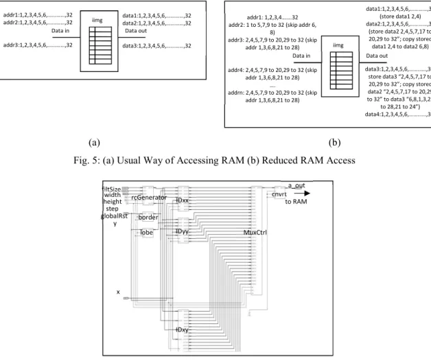
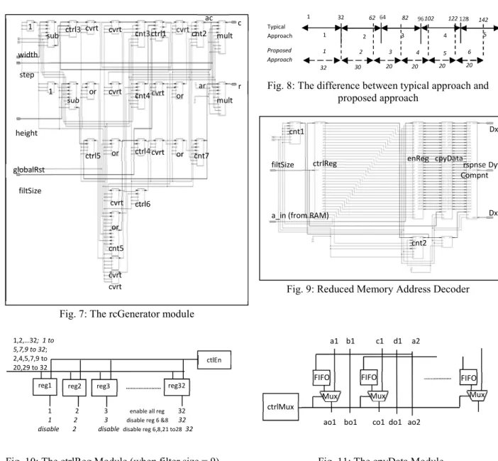
Based from our prior discussion, the observation shows that there are addresses to the external memory in the next round which are redundant or the same as addresses in the prior round. Since the latency to the external memory is more than the latency of the internal/on chip memory, we propose an additional circuit or a controller that can control the access to external redundant data. The proposed controller contains a FIFO chip memory that copies data that is still needed for the next round. As the data needed is already in the on chip memory, access to the external memory can be reduced. The design and implementation to calculate SURF Fast-Hessian is conducted using Xilinx ISE 10.1 tools. The design is divided into encoder and decoder module. The encoder will generate Fast Hessian response addresses which will be used to fetch the integral image (iimg) values stored in the external RAM. Fig. 5a and Fig. 5b illustrates the difference between the common way of accessing the external RAM and the proposed reduced RAM access to fetch iimg values when filter size = 9. The key idea of the proposed design is to limit the generation of redundant address to access the same location with similar data. Fig. 6shows the generated RTL schematic which consists of several modules. Table 6on the other hand shows the definition of the abbreviation used in the generated RTL schematic. The rcGenerator is the row and column generator which generates the image coordinates to be used by response component Dxx, Dyy and Dxy. The MuxCtrl is a module used to convert multiple parallel data generated from Dxx, Dyy and Dxy into single data which will be used to access single port memory via FIFO module. Following the example given in the previous section, this module will produce 2,814,336 addresses compared to 4,204,928 addresses using normal approach.
(a) (b)
Fig. 5: (a) Usual Way of Accessing RAM (b) Reduced RAM Access
The differences between the proposed design and the typical design lies in this rcGenerator module, where repeated or redundant addresses are discard to lessen the address generation and avoiding repeated address to be used to search for iimg data in the memory. In a typical implementation, the column values would be triggered every 32 counts to process 32 calculated addresses (i.e. 8 for Dxx & Dyy each, 16 for Dxy (refer to Appendix 1)). In the rcGenerator module (Fig. 7), ctrl1 is used to produce column coordinate (i.e. ac × step = c) values by enabling cnt2 counter based on the
rcGenerator border lobe IDxx IDyy IDxy MuxCtrl cnvrt to RAM filtSize width height step x globalRst y a_out addr1:1,2,3,4,5,6,…………,32 addr2:1,2,3,4,5,6,…………,32 addr3:1,2,3,4,5,6,…………,32 data1:1,2,3,4,5,6,…………,32 data2:1,2,3,4,5,6,…………,32 data3:1,2,3,4,5,6,…………,32
Data in Data out
iimg
55 Malaysian Journal of Computer Science, Vol. 32(1), 2019
filter values. If the filter size = 9 for instance, the column values will be triggered after 32 counts, followed by 30 counts and continues with 20 counts. Fig. 8shows the difference between the two implementations when filter size = 9. From Fig. 8 , it can be seen that the proposed approach is faster than the typical approach. The rcGenerator module also generates the row coordinate values (i.e. ar × step = r) which triggers cnt7 counter when ac and the width value is equal.
The decoder module (Fig. 9) is a module that produces the response component data Dxx, Dyy and Dxy based on the fetch integral image (iimg) data. These values will be normalized and applied to compute the determinant of Hessian response and Laplacian sign. In a normal implementation, the fetched iimg data can be distributed evenly to 32 registers to store 32 data (i.e. ABCD of Dxx1, ABCD of Dxx2, ABCD of Dyy1, ABCD of Dyy2, ABCD of Dxy1, ABCD of Dxy2, ABCD of Dxy3, ABCD of Dxy4) in each round. However, the data received by the decoder module (i.e. a_in) is the compressed iimg data fetched from the RAM according to the encoder module. Since a number of data have been discarded by the encoder module, the ctrlReg is programmed to enable the 32 registers in the enReg based on the encoder module. The register for the discarded data will be disabled to allow the next data to come in. If filter size = 9 for example, all the 32 registers will be enabled sequentially in the first round. In the next round, 30 registers will be enabled and in the following round only 20 registers will be enabled (Fig. 10). The data that will be used for the discarded data is stored in a FIFO inside the cpyData. A multiplexer will be used to choose between current data or the copied data inside the FIFO. Fig. 11 shows an example of the cpyData module where the input a2 can be used for both output ao1 and output ao2 based on the ctrlMux.
Fig. 7: ThercGenerator module
Fig. 8: The difference between typical approach and proposed approach
Fig. 9: Reduced Memory Address Decoder
Fig. 10: The ctrlReg Module (when filter size = 9) Fig. 11: The cpyData Module
sub sub ctrl3 cvrt cvrt cnt3 1 1 cvrt ctrl1 cnt2 mult or cvrt cnt4 cvrt or mult ctrl5 or ctrl4 cvrt or cnt7 cvrt ctrl6 or cnt5 cvrt cvrt c r filtSize height step width globalRst ac ar filtSize cnt1
a_in (from RAM)
cnt2 enReg
ctrlReg cpyData rspnse
Compnt Dxx Dyy Dxy 1 32 62 64 82 96 102 122 128 142 160 1 2 3 4 5 1 2 3 4 5 6 Typical Approach Proposed Approach 32 30 20 20 20 20 1,2,…32; 1 to 5,7,9 to 32; 2,4,5,7,9 to 20,29 to 32
1 2 3 enable all reg 32 1 2 3 disable reg 6 &8 32 disable 2 disable disable reg 6,8,21 to28 32
reg1 reg2 reg3 reg32
1
ctlEn
FIFO FIFO FIFO
Mux Mux Mux
ctrlMux
a1 b1 c1 d1 a2
56 Malaysian Journal of Computer Science, Vol. 32(1), 2019
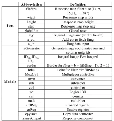
Table 6: The definition of the abbreviation used in Fig. 5, Fig. 6 and Fig. 8
Abbreviation Definition
Port
filtSize Response map filter size (i.e. 9, 15,21,…..,387) width Response map width height Response map height step Response map step size globalRst Global reset
x,y Original image size (width, height) a_out Address to fetch iimg
a_in iimg data input
Module
rcGenerator Generate image coordinates row and column (ndgrid) IDxx, IDyy,
IDxy
Integral Image Box Integral border Border for filter = b = (filtSize - 1) / 2 + 1)
lobe Lobe for filter =l= filtSize /3 MuxCtrl Multiplexer controller
cnvrt converter sub subtractor ctrl controller or Logical OR cnt counter mult multiplier
ctrlReg Control register enReg Enable register cpyData Copy data controller rspnseCmpnt Response component
6.0 PERFORMANCE COMPARISON
For performance comparison, a common approach encoder and decoder are developed using Xilinx ISE. Both typical and proposed approaches are synthesized and implemented using Xilinx Spartan 3a dsp FPGA. Table 7shows the device utilization and timing summary for both implementations. It can be seen, that the number of device utilization or area increase in the proposed approach is small. For the speed comparison (i.e. when octaves = 5, initial sample = 2 and image size = 377 × 300, DRAM access latency 20ns) the typical encoder and decoder completes the processing at (12.526 + 9.93 + 20)𝑛𝑠 × 4,204,928 𝑐𝑦𝑐𝑙𝑒𝑠 = 178.5ms when maximum clock speed (Table 7) is utilized. The proposed encoder and decoder on the other hand completes at (17.207 + 14.29 + 20)𝑛𝑠 × 2,814,336 𝑐𝑦𝑐𝑙𝑒𝑠 = 144.9 ms. In the software based implementation, the software encoder alone needs 116.3ms to complete its process using Intel(R) Core(TM)2 Duo CPU 2.33GHz, 3.23GB of RAM. This shows that the proposed FPGA-SURF implementation executes faster than the software implementation and the prior FPGA-SURF implementation.
Table 7: Device utilization and timing summary Normal Encoder Normal Decoder Proposed Encoder Proposed Decoder Number of Slices 2683 698 2816 967 Number of Slice Flip Flops 1284 905 1300 1210 Number of 4 input LUTs 4710 647 4941 1504 Number of DSP48s 63 4 63 4 Minimum period 12.526ns 9.930ns 17.207ns 14.290ns
57 Malaysian Journal of Computer Science, Vol. 32(1), 2019
7.0 DISCUSSION
Based on the results, it is found that the Fast Hessian computation consisting Dxx, Dyy and Dxy box filters response component computation, takes the longest processing time. Since SURF only varies in its filter size and discards the need to subsample an image, prior FPGA-SURF researchers applies parallelism to the SURF multiple layers of the scale-space pyramid. Hence, the Fast Hessian computation of SURF can be done in parallel. Though parallel design is proposed, the limitation caused by the memory access has not been discussed thoroughly. Seeing that SURF requires frequent memory access to fetch the integral image data (i.e. iimg), a close study on the address generation to fetch the integral image data is conducted.
Based on the study, we discover that the address generation comprises significant redundant repetitive patterns that can be safely discarded. Thus, an additional circuit is proposed to be inserted into the original encoder and decoder of the original response component module. The additional encoder circuit is designed with a controller that skips generating redundant or similar address location as the prior generated addresses. Before the address is skipped, the address that will be used by the subsequent round is stored in a FIFO located in the encoder module. The purpose of the additional circuit is to reduce the access to the external memory such as SDRAM. Though the external memory is needed to store large integral image data, it suffers from a significant amount of access latency. This is due to the dynamic characteristic of an SDRAM which has to be refreshed periodically to maintain its content. The latency forces the memory controller to wait between data request. Other than that, the switching process between its memory space (i.e. banks, rows and columns) will produce some overhead. Typical SRAM (i.e. on-chip) access latency is between 2-3 ns while DRAM has 20-35 ns access latency. DRAM has also higher cycle time of 2 times its access latency since it cannot begin new access while refreshing. For this reason, a FIFO using FPGA on chip memory is chosen to regulate the flow of data from one module to another. The on chip memory typically has a latency of only one clock cycle, it has the highest throughput and has the lowest memory latency in an FPGA based system. In this design, the on chip memory access only consider maximum of 4 rounds buffering to suite the limited capacity of the on chip memory. The result in Table 7shows that the number of slices and minimum period has increased. Since additional circuit to skip and duplicate redundant addresses is included in the proposed design, the increase on the number of slices can’t be avoided. However, the slight increase doesn’t affect much the overall area of the FPGA design. The slight increase in the minimum period also doesn’t affect the overall execution time. This is due to the fewer data generated by the proposed design and the reduction of 1.49 (i.e. 4,204,928/2,814,336) times external memory access. From the result, it can be shown that the proposed design able to execute 23% faster than the original approach when DRAM access latency is at 20 ns. The proposed method will also show higher speed improvement if larger image size is implemented. 8. CONCLUSION
The purpose of this paper is to improve prior FPGA-SURF implementation conducted by prior researchers such as Svab et al. [31], Bouris et al. [32], Schaeferling et al. [33]. Since the most time consuming part of SURF is not highlighted by these researchers, a software profiling tool is utilized to find section of program that demands the most processing time. The software profiling result shows that one of the reasons for the slow execution time is caused by the frequent external memory access to fetch the integral image data. In this paper, the memory access analysis shows that about 33% (i.e. (4,204,928 − 2,814,336)/ 4,204,928) of the access are redundant and can be discarded. Therefore, additional circuit on top of the original response component module is proposed to avoid the redundant memory access. As shown from the result, though there is an increase to the minimum period of the proposed encoder and decoder, the increase is compensated by the fewer data to be processed. The result shows that the proposed design able to execute 1.23 times or 23% faster when external latency is 20ns. The external memory such as SDRAM suffers from a significant amount of high access latency and always greater than the FPGA on chip memory proposed in this design. Therefore, the proposed design will be able to speed up the overall FPGA-SURF implementation.
ACKNOWLEDGEMENT
This project is funded by University of Malaya Research Grant (RP036-15AET, RG112-12ICT) and Bright Sparks Unit, University of Malaya, Malaysia.
58 Malaysian Journal of Computer Science, Vol. 32(1), 2019
REFERENCES
[1] Idris, M.Y.I., Arof, H., Tamil, E.M., Noor, N.M., Razak, Z., “Review of Feature Detection Techniques for Simultaneous Localization and Mapping and System on Chip Approach”, Information Technology Journal, Vol. 8, No. 3, 2009, pp. 250-262.
[2] Idris, M.Y.I., Arof, H., Noor, N.M., Tamil, E.M., Razak, Z., “Improving Monocular Slam Inverse Depth Parameterization Computation Time via Software Profiling and Parallel Matrix Multiplication”, International Journal of Innovative Computing, Vol. 7, No. 11, November 2011, pp. 6273-6287.
[3] Idris, M.Y.I., Arof, H., Noor, N.M., Tamil, E.M., Razak, Z., Wahid, A., “A Novel Approach of an FPGA Design to Improve Monocular Slam Feature State Covariance Matrix Computation”, International Journal of Innovative Computing, Vol. 8, No. 3(A), March 2012, pp. 1987-2000.
[4] Zhang, Chengjun., Wang, Chunyan., and Ahmad, M. Omair., “A pipeline VLSI architecture for fast computation of the 2-D discrete wavelet transform.” IEEE Transactions onCircuits and Systems I: Regular Papers, Vol. 59, No. 8, 2012, pp. 1775-1785.
[5] Harris, C., Stephens, M., “A combined corner and edge detector”, in Proceedings of the Alvey Vision Conference, 1988, pp. 147 – 151.
[6] Moravec, H., 1981. “Rover visual obstacle avoidance”, in International Joint Conference on Artificial Intelligence, Vancouver, Canada, pp. 785-790.
[7] Lindeberg, T., “Detecting salient blob-like image structures and their scales with a scale-space primal sketch: a method for focus-of-attention”, International Journal of Computer Vision, Vol. 11, No. 3, 1993, pp. 283-318.
[8] Lindeberg, T., “Scale-space theory: A basic tool for analysing structures at different scales”, Journal of Applied Statistics, Vol. 21, No. 2, 1994, pp. 224-270.
[9] Mikolajczyk, K., Schmid, C., “An affine invariant interest point detector”, in Proceedings European Conference on Computer Vision, 2002, pp. 128 – 142.
[10] Baumberg, A., “Reliable feature matching across widely separated views”, in Proceedings of the Conference on Computer Vision and Pattern Recognition, Hilton Head Island, South Carolina, USA, 2000, pp. 774–781. [11] Mikolajczyk, K., Schmid, C., “Indexing based on scale invariant interest points”, in Proceedings of the 8th
International Conference on Computer Vision, Vancouver, Canada, 2001, pp. 525–531.
[12] Cabani, C., MacLean, W.J., “A Proposed Pipelined-Architecture for FPGA-Based Affine-Invariant Feature Detectors”, in Computer Vision and Pattern Recognition Workshop, June 2006. pp. 17-22.
[13] Mikolajczyk, K., Schmid, C., “Scale and affine invariant interest point detectors”, International Journal of Computer Vision, Vol. 60, No. 1, 2004, pp. 63–86.
[14] Tippetts, B., Fowers, S., Lillywhite, K., Lee, D.J., Archibald, J., 2007. “FPGA Implementation of a Feature Detection and Tracking Algorithm for Real-time Applications”, Lecture Notes in Computer Science, Advances in Visual Computing, Vol. 4841, 2007.
[15] Hsiao, P.Y., Lu, C.L., Fu, L.C., “Multilayered Image Processing for Multiscale Harris Corner Detection in Digital Realization”, IEEE Transactions on Industrial Electronics, Vol. 57, No. 5, May 2010.
[16] Tomasi, C., Kanade, T., “Detection and tracking of point features” Technical Report CMU-CS-91-132, Carnegie Mellon University, April 1991.
[17] Benedetti, Perona, P., “Real-Time 2-D Feature Detection on a Reconfigurable Computer”, in IEEE Computer Society Conference on Computer Vision and Pattern Recognition (CVPR'98), pp.586.
59 Malaysian Journal of Computer Science, Vol. 32(1), 2019
[18] Bissacco, A., Ghiasi, S., “Fast visual feature selection and tracking in a hybrid reconfigurable architecture”, in 2nd Workshop on Applications of Computer Vision, ECCV 2006, Gratz, May 2006.
[19] Claus, C., Huitl, R., Rausch, J., Stechele, W., “Optimizing the SUSAN Corner Detection Algorithm for a High Speed FPGA Implementation”, in 19th International Conference on Field-Programmable Logic and Applications (FPL 2009), pp. 138-145.
[20] Smith S. M., Brady, J. M., “Susan - a new approach to low level image processing”, in International Journal of Computer Vision, Vol. 23, 1997, pp. 45-78.
[21] Lowe, D.G., “Object recognition from local scale-invariant features”, in International Conference on Computer Vision, Corfu, Greece, 1999, pp. 1150-1157.
[22] Lowe, D.G., “Distinctive Image Features from Scale-Invariant Keypoints”, International Journal of Computer Vision”, Vol. 60, No. 2, November 2004, pp. 91-110.
[23] Wan-Lei Zhao., and Chong-Wah Ngo., “Flip-Invariant SIFT for Copy and Object Detection”, IEEE Transactions on Image Processing, Vol. 22, No. 3, 2013, pp. 980-991.
[24] Se, S., Ng, H., Jasiobedzki, P., Moyung, T., “Vision Based Modeling And Localization For Planetary Exploration Rovers”, in 55th International Astronautical Congress 2004, Vancouver, Canada, 4-8 Oct 2004. [25] Barfoot, T.D., “Online Visual Motion Estimation using FastSLAM with SIFT Features”, in IEEE/RSJ
International Conference on Intelligent Robots and Systems, 2005. (IROS 2005), 2-6 Aug. 2005, pp. 579- 585. [26] Chati, H.D., Muhlbauer, F., Braun, T., Bobda, C., Berns, K., “Hardware/Software co-design of a key point
detector on FPGA”, in International Symposium on Field-Programmable Custom Computing Machines 2007, 23-25 April 2007, pp. 355-356.
[27] Bay, H., Tuytelaars, T., and Gool, L.V., “SURF: Speeded Up Robust Features”, Computer Vision and Image Understanding, Vol. 110, No. 3, 2006, pp. 346-359.
[28] Ke, Y., Sukthankar, R., “PCA-SIFT: A more distinctive representation for local image descriptors”, in Proceedings Computer Vision and Pattern Recognition, 2004, pp. 506 – 513.
[29] Mikolajczyk, K., Schmid, C., “A performance evaluation of local descriptors”, IEEE Pattern Analysis Machine Intelligence(PAMI) 27, 2005, pp. 1615–1630.
[30] Juan, Luo. And Gwun, Oubong., “A Comparison of SIFT , PCA-SIFT and SURF”, International Journal of Image Processing, Vol. 3, No. 4, 2009, pp. 143-152.
[31] Svab, J., Krajnik, T., Faigl, J., Preucil, L., “FPGA Based Speeded Up Robust Features”, in IEEE International Conference on Technologies for Practical Robot Applications 2009, 9-10 Nov. 2009, pp. 35 – 41.
[32] Bouris, D., Nikitakis, A., Papaefstathiou, I., “Fast and Efficient FPGA-Based Feature Detection Employing the SURF Algorithm” in 18th IEEE Annual International Symposium on Field-Programmable Custom Computing Machines (FCCM), 2-4 May 2010, pp. 3 – 10.
[33] Schaeferling, M., Kiefer, G., “Flex-SURF: A Flexible Architecture for FPGA-Based Robust Feature Extraction for Optical Tracking Systems”, in International Conference on Reconfigurable Computing and FPGAs (ReConFig), 13-15 Dec. 2010, pp. 458 – 463.
[34] Krajnik, Tomas., Svab, Jan, Pedre, Sol., izek, Petr C., Preucil, Libor., “FPGA-based module for SURF extraction”, Machine Vision and Applications, Vol. 25, 2014, pp. 787–800.
[35] Evans, C, “Notes on the OpenSURF Library; January 2009, Technical Report CSTR-09-001”, University of Bristol
60 Malaysian Journal of Computer Science, Vol. 32(1), 2019
Appendix 1 (Filter Size = 9)
Note: negative values will be converted to 1
1 2 3 4 5 6 7 8 addr 9 10 11 12 13 14 15 16 addr 17 18 19 20 21 22 23 24 addr 25 26 27 28 29 30 31 32 addr
61 Malaysian Journal of Computer Science, Vol. 32(1), 2019
Appendix 2 (Filter Size=15)
Note: negative values will be converted to 1
1 2 3 4 5 6 7 8 9 10 11 12 13 14 15 16 17 18 19 20 21 22 23 24 25 26 27 28 29 30 31 32