DEVELOPMENT OF A WELDING COST ESTIMATION
MODEL BASED ON THE FEATURE CONCEPT
Masmoudi, F.
*; Hachicha, W.
**& Bouaziz, Z.
*** *Unit of Mechanic, Modelling and Production (U2MP),B.P. W, 3038 Sfax, Tunisia
**Department of Mechanical Engineering, Engineering School of Sfax, B.P. W, 3038 Sfax, Tunisia
***Laboratory of mechanics, solids, Structures and technological development, Higher School of Sciences and Technology, BP 56 Beb Mnara 1008 Tunis, Tunisia
E-Mail: [email protected], [email protected]
Abstract:
This paper presents a cost estimation model of weld assemblages. It is based on the product decomposition into parts and then into assemblages. The study is about a proposition of an original definition of welding and preparing features attributed to each assemblages. It is based on knowledge modelling at the level of process and product perception. The decomposition of the product into features and the identification of cost features remain manual. The proposed model consists in combining two cost estimating model applied to the products and to the processes. First, we have used an analytic model for the formalizing of the welding time, of the electrode consumption and of gas consumption according to the different parameters of the preparing and the welding features. Second, we have used the parameter method for the cost structuring caused by the different feature-cost (cost entity) preparing and by the feature-cost welding.
Key Words: Cost Estimating, Manufacturing Features, Feature Cost, Welding
1. INTRODUCTION
The setting up of a reliable system concerning the estimation of costs, takes a considerable importance for the manufacturing enterprises working on request. The accuracy and the rapidity given by a cost estimating method contribute to the order confirmation by the client. The manufacturing costs is generally obtained by the produce of a part manufacturing time and the manufacturing time estimation methods namely [1]:
(1) the analytic method: which allows to evaluate a product manufacturing time thanks to the decomposition of an elementary manufacturing operation set. We define, for each operation, the necessary time from which we can calculate the manufacturing cost: "Manufacturing time multiplied by the manufacturing hourly cost".
(2) the parameter method: which is based on the utilization of mathematical relations founded on the information gathered by the enterprise so as to be able to determine if there exist the correlations between the different times and the manufacturing operations.
(3) the analogue method: which is based on the classification and the indexes of the products to manufacture by the enterprise according to morpho-dimensional criteria and to quality. The new product cost is estimated by comparison with reference to the last newly indexed products.
The analytic method consists in describing and developing the whole of operations necessary for the production of the product, this method is known for its accuracy and by its slowness as well. To replace the analytic approach, many enterprises move towards the analogue and the parameter methods. If these methods are relatively rapid, it is because they are essentially synthetic and function in total darkness. They provide the product cost
according to certain characteristics, which limit the negotiating transparency of marketing men.
In the field of mechanics, several works have been carried out, in particular in the cost estimating of forged parts [2], of cylindrical parts [3], of parts machined by the application of the analogue method [4], of parts machined by the application of the parameter method [5], etc. The cost calculation for most of these methods depends on the accuracy of the machining time estimating method. The present evolution of cost estimating methods [6-11], consists in integrating at the same time the product geometric and technical characteristics which will remain the same during the whole manufacturing process. This presents the modelling basis by feature. This method is used, throughout this study, to develop an application of welded assemblages for metallic structures.
In this paper, we propose the modelling principle of an assemblage mechano-welded by two features: "a preparing feature" and "a welding feature" so as to calculate the time relative to each operation using the analytic model. Then, we apply the principle of feature cost for each activity allowing estimation of assemblage total costs.
The outline of this research is as follows. In the first part, we’ll present the method of welded assemblage time and cost estimation. Then, we will explain the decomposition of a structure into assemblages. This work results in the introduction of new notions of welding and preparing features. In a second part, we will describe the relation between the technological features and the welding time calculation. For this, we will give details of the analytic models developed for each type of features. Finally we will present the concept feature cost which allows the cost estimating relating to each operation then the application of this concept to preparing cost estimating (borders machining, weld pointing, etc) and to welding.
2. COST AND TIME ESTIMATING MODEL
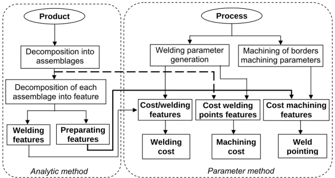
The purpose of this study is to provide a model, which integrates the necessary information to define the product and its manufacturing process, so as to answer a cost and time estimation. To do this, the proposed model, which is presented in Fig.1 contains two sub models (parts).
Figure 1: Model proposed for the welding cost estimation.
Product Process Decomposition into assemblages Welding parameter generation Decomposition of each
assemblage into feature
Machining of borders machining parameters Welding features Cost machining features Cost welding points features Preparating features Cost/welding features Machining cost Weld pointing Welding cost
The first part consists on geometric and technological description of assemblages in welding features and in preparing features. In this part, an analytic model is proposed for the formalizing of the welding time, of the electrode consumption and of gas consumption according to the different parameters of the preparing and the welding features. The second part defines how to conceive these features. The costs estimating model proposed is based on the definition of the volume of the material added in welding by a geometric description of the welding joint in the assembling area. The knowledge of the filling metal characteristics and the welding mass flow, allow the determination of the welding time for each welding feature. In the second part, the parameter-method is applied for the cost structuring generated by the different feature-costs, which compose the welding process.
3. WELD ASSEMBLAGE MODELLING
The modelling of a weld assemblage takes into account the preparing operation which itself depends on the chosen welding process and on the weld position. For each assemblage, we define two types of features: welding feature and preparing feature.
3.1. Decomposition of a mechano-weld structure
We propose an approach based on the decomposition of the metallic structure to weld in n assemblages. This structure will be called "P" in the next part of this paper, see Fig. 2. Each assemblage is carried out by two types of operations: preparing operations and welding operations. This decomposition is given by the set of assemblages, which also includes the weld technical parameters. In the approach of the assemblage decomposition, which mentioned in Fig. 2, the survey of the mechano-weld structure, since its conception plans the weld joint number for each assemblage. We attribute for each given assemblage Aij, Kij welding features associated to preparing features. Each assemblage may contain one or several welding features and after that one or several preparing features.
Figure 2: Approach for decomposition of "welding features" and "preparing features" The welding and preparing features concepts rest on the analysis approach of the following characteristics:
• shape characteristics: they describe geometric shapes often peculiar to an application feed in welding;
• material characteristics: they correspond to the nature of basic materials, their treatment, etc.;
• process characteristics: they collect the information about the welding process (arc, resistance, etc), etc.;
• assemblage characteristics: they regroup the linking conditions, the position and orientation of parts, the assembling type, etc.
Part "p1" Part "pi" Part"pj" Part "pn"
Assemblage: Aij Assemblage: Aii Welding feature: ES1ij Product "P" Preparing feature: EP1 ij … … Welding feature: ES2ij Preparing feature: EP2ij Welding feature: ESkij Preparing feature: EPk ij
3.2. Feature model Preparing features
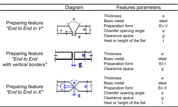
The preparing feature includes the machining of borders in V, X etc and also the positioning of the parts to weld one according to the other (gap, alignment, pointing, etc). It is principally defined by the geometric shape, which defines the space to be filled with the filling metal. Table I presents examples of preparing features in V, in straight borders and in X. Among these preparing features, there are some, which are technically and economically recommended, we mention here: recommended preparing features.
Table I: An example of a preparing feature parameter.
Diagram Features parameters Preparing feature
"End to End in V"
Thickness e
Basic metal steel
Preparation form En V
Chamfer opening angle α
Clearance apace g
Heel or height of the flat t
Preparing feature "End to End with vertical borders"
Thickness e
Basic metal steel
Preparation form En l
Clearance apace g
Preparing feature "End to End in X"
Thickness e
Basic metal steel
Preparation form En X
Chamfer opening angle α
Clearance apace g
Heel or height of the flat t Welding feature
According to the welding process and techniques, the weld joint is obtained in one or several processes executed by the operator. The welding feature is principally defined by the parameter presented in Table II.
Table II: Parametring of a welding feature
Technical parameters
Basic metal Example : steel
Thickness e (mm)
Assembling type Example : End to End Welding position Example : Flat Welding process Example : SMAW Number of re-starting z Welding intensity I (A) Type of current Example : continued Electrode diameter φ (mm)
Electrode output ρ
Protection gas density D Geometric parameters
Weld section SS
4. TIME AND COST CALCULATION
4.1. Analytic method calculation of the welding time
To estimate the feature welding time for an assemblage, we propose an approach based on the evaluation of the welding section from a geometric modelling.
Geometric modelling
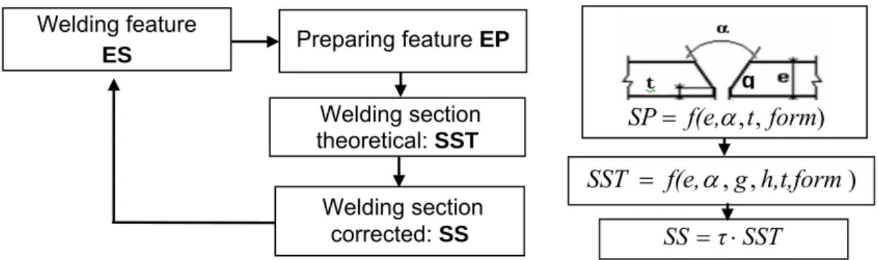
Fig. 3 presents the approach to calculate the welding section based on the geometric parameters of the corresponding feature preparing.
Figure 3: The geometric modelling approach of a welding section.
The geometric modelling related to each preparing feature must be saved in a technical data base. To explain the approach we are going to treat the example of preparing feature end to end in V. Fig. 4 presents an example of a geometric modelling in order to determine the welding section.
Figure 4: Geometric modelling of a welding feature "End to End" in V.
The preparing feature section marked "SP" is represented by two times the surface T. The theoretical welding section is given by the fallowing equation:
T
R
B
SST
=
+
+
2
(1)
To determine "SST", it is necessary to calculate: - the two triangles section "T" which is expressed by:
t) (e g) (l T = − − 2 2
(2)
where)
α
tg (
t)
(e
g
l
2
2
−
+
=
(3)
Preparing feature EP Welding section theoretical: SST)
,
,
g
h,t,form
f(e,
SST
=
α
Welding feature ES Welding section corrected: SS SS =τ⋅SST)
,
,
t
form
f(e,
SP
=
α
g l g h t Part i R T T B Part j e- R which is the triangle surface with a length "g" and with "e",
e
g
R
=
⋅
(4)
- B is estimated at 75 % of the rectangle section of a length "l" and a width "h". So:
h
l
B
=
⋅
⋅
4
3
(5)
According to (1), we can write that:
h
l
)
α
tg(
t)
(e
e
g
SST
=
⋅
+
−
+
⋅
⋅
4
3
2
2(6)
By replacing the expression of "l" in the equation (6), we get : h g ) α tg( h) t (e t) (e e g SST = ⋅ + − ⋅ − + ⋅ + ⋅ ⋅ 4 3 2 2 3
(7)
Generally, the welder can’t respect exactly the limits of the preparing section whileexecuting the welding operation. For this reason, we suppose that the section SST must be corrected by a coefficient "τ". The relation between the theoretical SST and the actual section is written:
SST
τ
SS= ⋅
(8)
"τ" is practically near the unity in the case of an automatic application of the welding operation.
Welding time estimation
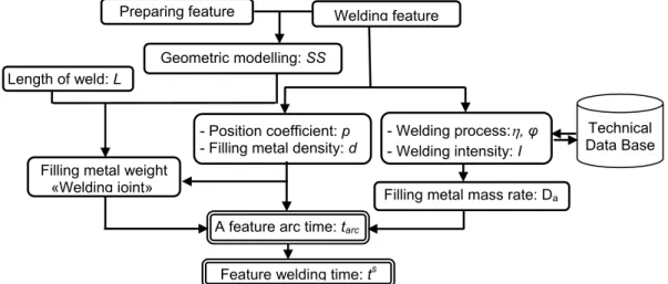
The principle consists in establishing a simple cost estimating system which closely associates the technical parameters (welding features), and the geometric parameters. To determine a feature welding time, it is necessary to determine the geometric parameters so as to calculate the volume of the filling metal in the welding area. When we know the basic metal density, we can determine the weight of the weld joint and then the welding time see the organigram present in Fig. 5.
Figure 5: Welding time calculating methodology.
Filling metal weight
«Welding joint» Filling metal mass rate: Da
A feature arc time: tarc Length of weld: L
Preparing feature
- Welding process:η, φ
- Welding intensity: I Welding feature
Feature welding time:ts - Position coefficient: p - Filling metal density: d
Technical Data Base Geometric modelling: SS
The use of time estimating analytic method can be perfectly considered. The estimating approach of the welding time is organized around the following four stages:
Stage 1: welding volume evaluation. It is the produce of the welding section by the
welding length:
ij s
SS
.L
V
=
(9)
Where Lij : welding length SS : welding section
Stage 2: Amount of Welding Wire
η .d V ρ m s a ⋅ =
(10)
Where d : the filling metal density η : the process efficiency
ρ : the electrode output
Stage 3: The electrode time "tarc" is the electrode and protecting gas consuming time. It is expressed by: a a arc D m t =
(11)
Stage 4: the welding operation executing time is the arc time corrected thanks to the
operator efficiency and to the coefficient of the positioning difficulty:
ϕ
arc S p tt = ⋅
(12)
Where ϕ : the process depending on the operator efficiency;
p : this coefficient depends on the complexity of the weld positioning and of the assemblage type.
Basing on the formulas (9), (10), (11) and (12), for one feature, we can write:
ij a S . SS L D d η p ρ t ⋅ ⋅ ⋅ =
ϕ
(13)
4.2. Cost estimationDefinition of the cost feature approach
We adopt the cost feature definition proposed by [5] and [6]: "A feature cost is a grouping of costs associated to resources consumed by one activity. The fundamental condition cares about the homogeneity of the resources consumed by the feature cost which allows associating them to an indicator".
The feature cost modelling objective is to provide a model which integrates the necessary information to the definition of the product and of its manufacturing process so as to ensure cost estimation in a preparing phase to the manufacturing.
Cost parameter formulation
For a given manufacturing process, the concept feature cost allows on one hand to estimate the direct cost corresponding to the manufacturing operation by determining for each of them the indicator of the corresponding "feature cost".
Given "Ci" the activity cost "I" and Ri = R1, R2, …, Rk the whole of the resources consumed for this activity. By definition the cost of a resource is written:
A resource cost = Inductor (number) * αk(hour/number) * charging rate (cost/hour) Then, a resource cost is written k:
k k i α C
x
C = ⋅ ⋅
(14)
Where αk : resource consumption coefficient k xi : activity inductor "I"
Ck : charging rate for the resource k
The model basic equation giving an activity cost will be then the sum total costs of different resources [3]: k k i R k i x α C C i ⋅ ⋅ =
∑
∈(15)
To identify the inductors, we can use several methods like the expert consulting or adetail survey of the activity or at last, basing on a sufficient number of historical data of a quite large number of inductors by selecting the most influent ones.
Preparing cost estimation
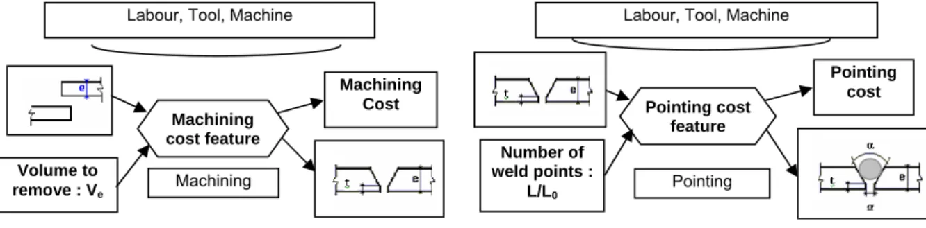
Each preparing feature calls for intrinsic parameters, which describe the product and also for the position and the orientation geometric characteristics. So, the cost preparation feature is composed of the cost machining feature, Fig. 6 (a) and of the pointing cost feature Fig. 6 (b).
(a) The structure of the machining cost feature (b) The structure of the pointing cost feature
Figure 6: Cost feature structure.
It is quite evident that the machining cost feature has the volume of the material to remove indicated "Ve" as indicator. In the application of the equation (14), the machining cost is the sum total of the resources costs which compose the machining cost feature.
ECU OU ECU MA ECU MO U
C
C
C
C
=
+
+
(16)
Machining cost feature Volume to remove : Ve Machining Cost Machining Labour, Tool, MachinePointing cost feature Number of weld points : L/L0 Pointing cost
Labour, Tool, Machine
where CECU Ve αu Cu
MO = × × : is the labour cost mu
um e ECU
MA V α C
C = × × : is the machine utilizing cost
o
C
α
V
C
ECU e uoOU
=
×
×
: is the lubricant and tool consumption costCu : Labour hourly cost
Cmu : machine utilizing houry cost Co : tool wear hourly cost
Ve : volume of material to remove
αum : machine utilizing coefficient
αuo : lubricate and tool consuming coefficient.
We note "αu" the coefficient to measure the time consuming by volume of material removed and it is expressed in hour/cm3. This coefficient is given by:
v u
D
c
α
=
(17)
Where Dv : the machining volume rate.
c : a complexity index (c≥1): we associate to each type of preparing feature a complexity index which will be a parameter depending on the preparing technology adopted by the enterprise. It can be determined from a statistic approach applied to each type of feature and initialized according the experience.
To calculate the machining time for the "End to End" type preparation, we can write the following relation: v U
D
L
.SP
c
t
=
⋅
(18)
Where SP : preparing feature section of an assemblage. L : length of the assemblage weld.
c : complexity index according to the form of preparation. Dv : machining volume rate.
The pointing allows a conformable disposition of the two parts to weld. It also allows to juxtapose the borders one according to the other and after that, it controls the space all along the weld path "L". We note "αp" the coefficient which measures the time consumption it takes to make a point weld which remains subject to the difficulties of execution and of accessibility.
0
t
λ
αp = ⋅
(19)
Where λ : the coefficient linked to the difficulties, with
λ
≥
1
t0 : the elementary time to achieve a point of weldThe resources cost of the feature "pointing cost" is principally composed of the labour cost and the weld consuming cost for the pointing.
- The labour cost for the pointing is written:
p 0 0 C L L t λ CECP MO = ⋅ ⋅ ⋅
(20)
Where Cp : labour hourly cost for the pointing operation L/L0 : the number of points
- The pointing cost is the sum total of the resources costs, which compose the pointing cost feature. ECP MA ECP MO P C C C = +
(21)
We assume that the cost of one point of weld is neglect-able compared to the total welding cost.
Welding costs estimation
Subsequent to the analytic modelling applied to the scale of a feature, according to the relation (13) which determines the welding time, we can write:
a a S D m p t
ϕ
=(22)
It is to remark that there is a harmony with the feature cost approach. In fact, if we take the mass of materiel to be added as a convenient inductor for the welding operation, then we can write that the time consuming coefficient of the weld noted "αs" as follows:
a s
D
p
α
⋅
=
ϕ
(23)
After having estimated the total time of welding, it has become possible to make a detailed cost calculating of each consumption engendered by the welding activity.
- The labour cost is:
s S a S MO m α .C C = ⋅
(24)
Where Cs : Labour hourly cost "UM/mn" - The eletrode consuming cost is:
e a S
EL
m
.C
C
=
(25)
Where Ce: electrode cost by mass unit "UM/g"
It is clear that the consuming coefficient of the resource "Electrode" is - The gas consuming cost is:
g a a S GA
.m
C
D
χ
D
C
=
⋅
⋅
(26)
Where D : protection gas density in "g of gas / cm3" χ : the gas volumic rate in "cm3/mn"
Cg : gas cost by mass unit "UM / g of gas" - The consumption coefficient of the resource "gas" is:
a Gaz S
D
χ
D
α
=
⋅
(27)
- The consumption cost of electric energy is: k a a S EE C D μ U.I.m C ⋅ ⋅ = 60
(28)
Where I : current intensity "A"
U : the electric current tension "V" Ck : electric energy cost in "UM/kWh" µ : the transformer average output - The electricity consumption coefficient is:
a EL S D μ U.I α ⋅ ⋅ = 60 "kWh/g"
(29)
- The utilization cost of the welding post: It corresponds to the cost engendered when the
post in function. To determine it, it is necessary to know welding machine hourly cost, "Cms". It is expressed as follows: ms a a S Ma C D m C = ⋅
(30)
The consumption coefficient of the resource (post utilization) is
a Poste S
D
α
=
1
"mn/g"The total weld cost is the sum total of the elementary costs: labour, electrode conception, protecting gas conception, electricity consumption and welding post. It is written as follows: S MA S EE S GA S EL S MO S
C
C
C
C
C
C
=
+
+
+
+
(31)
In any case, the raw material cost is not to neglect. It is evident that it is considered during the welding operation.
To generalize, the total welding cost of a feature "q" is the sum total of the machining cost, the pointing cost and of the welding cost for each feature.
P q U q S q T q C C C C = + +
(32)
The total welding cost of an assemblage (i,j) is then the sum total of all the welding costs of the feature which composes it:
∑
==
k(i,j) q T q T(i,j)
C
C
1(33)
Where k (i,j): the number of assemblage (i,j) welding features.5. IMPLEMENTATION
The proposed cost estimation model for a weld assemblage based on the concept feature is implemented to a software model for computer aided costs estimation, which is presented in [12]. The developed software which called SOUDABASE constitutes an aided decision tool to calculate the cost and establish the sales conditions by the experts. It provides an informational model that integrates the information necessary to the defining of the product and of its manufacturing process.
In order to validate the proposed model, we develop the example of Fig. 7 to show the efficiency of SOUDABASE tool. The set for which have tried to estimate the welding cost is a Chassis. This set is interesting in the sense that is allows us to put into evidence the cost estimating problems, mentioned earlier.
Figure 7: The schema of the Chassis.
5.1. Proposed model estimations
The most recommended technical welding process for the Carbon steel machining is the GMAW with a gas of (75% Ar + 25% CO2) type. The diameter of the electrode for all the welding operation is 1.2 mm. This last parameter is according to the accessibility of the electrode in the joint to weld. On the contrary the electrode output is determined in concordance with welding process type. In our case the output is equal to 100%. The length of the assemblage is determined for each type of feature which presented in Table III.
Table III: Specifications of different types of features of the chassis
Feature Type Leg Size (mm) Intensity (A) Weld length (m)
1 4,2 160 0,66 2 5,6 185 0,6 3 4,2 160 0,7
After defining the features of the Chassis, we have introduced the hourly costs of consumption to result in costs. Thus we have associated a cost model for each assemblage. The cost of a model presents the different unit costs (labour, gas, electrode and electricity). The assemblage times, the consumption and the costs will be, respectively, the sum total of the different features. These cost and time estimation are presented in Table IV.
5.2. DEVISOUD estimations
In order to validate model results, we have used another estimation tool which named DEVISOUD. It is estimation software was developed by the French centre CETIM Senlis France (Technical centre of mechanical industries). Detailed description of DEVISOUD software can be found in [13].
5.3. Manufacturing of Chassis
The main thing, for the manufacturing responsible of the collaborating company which named "engineering and industrial construction" (MDI) is the total weld the total length evaluation and the number of passes necessary for the welding costs and time estimation.
In the "Chassis" example we have studied the weld length being of 1.96 m. According to the expertise of the company, only one pass is required to weld a 1,2 mm sheet metal. We have calculated the total welding time of a tank which is equal to 14 min. others measurements of different timings noted down after the welding time are indicated in Table IV. We call back that the implementation of "SOUDABASE" results, a manufacturing and welding time equal to 13.15 min.
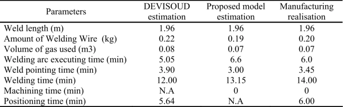
Table IV: Comparative estimations and trials results
Parameters
DEVISOUD
estimation
Proposed model
estimation
Manufacturing
realisation
Weld length (m)
1.96
1.96
1.96
Amount of Welding Wire (kg)
0.22
0.19
0.20
Volume of gas used (m3)
0.08
0.07
0.07
Welding arc executing time (min)
5.05
6.6
6.0
Weld pointing time (min)
3.90
3.00
3.45
Welding time (min)
12.00
13.15
14.00
Machining time (min)
N.A
0
0
Positioning time (min)
5.64
N.A
6.00
We note that the error obtained between the time calculated by our approach and the real welding time is very small. Its average is of the size of 10 % in this case. This difference remains small to the DEVISOUD results which show the accuracy of our calculating approach.
6. CONCLUSION
In this paper, we have explained the concept and the basic principle peculiar to our approach of time and cost estimating in parts welding. The model by feature which we have developed is characterized by the weld geometric description and by the volume defining of the material added in welding.
The formalization of the welding time is carried out by an analytic method of gas and electrode consumption according to the feature different geometric parameters and to the welding process. The cost estimating is assured by a parametric approach. The model includes all the stages of the welding process: preparation and weld.
To automatize the cost generating process, it is necessary to integrate the modelling of knowledge, the modelling of the arguments for the generating of preparation and weld features allowing the identifications of the features cost as well as their suitable inductors. Extending the proposed approach to this direction is our interesting research perspective.
7. ACKNOWLEDGEMENTS
We would like to thank the manufacturing responsible of the collaborating company "engineering and industrial construction" MDI for their valuable and constructive helps on the manufacturing realisation in this study.
REFERENCES
[1] Lallemand, H. (1999). Méthodes de chiffrage et indicateurs de la fonction devis, Journal Travail et Méthode, 545, 35-44
[2] Berlioz, M.; Martin, P.; Tichkiewitch, S. (1998). A fast and reliable cost estimation tool for Hot-forged parts, Proceedings of the Second International Conference on Integrated Design and Manufacturing in Mechanical Engineering, 985-992
[3] Seddiki, A.; Moisan, A.; Levaillant, G. (1995). Proposition d’un Système d’Assistance à l’Elaboration de Devis d’Usinage basé sur le concept d’entité, Journal Mécanique Industrielle et Matériax, Vol. 48, 5
[4] Duverlie, P. (1999). Méthode analogique appliquée aux pièces usinées, Journal Travail et Méthodes, 553, 20-24
[5] Jimenez, A. (1995). Méthode paramétrique- statistique : application aux pièces usinées, Journal Travail et Méthodes, 522, 19-25
[6] H’mida, F.; Martin, P.; Vernadat, F. (2005). Cost estimation in mechanical production: The Cost Entity approach applied to integrated product engineering, International Journal Production Economics, doi: 10.1016/ j. ijpe. 2005.02.016
[7] Bouaziz, Z.; Younes, J.B.; Zghal, A. (2002). A Fast and Reliable Tool for Estimates for Plastic Blowing Moulds, International Journal of Advanced Manufacturing Technology, 20, 545-550 [8] Shebab, E.; Abdalla, H. (2002). An Intelligent Knowledge-Based System for Product Cost
Modelling, International Journal of Advanced Manufacturing Technology, No. 19, 49-65.
[9] Jong-Yun, J. (2002). Manufacturing Cost Estimation for Machined parts based on Manufacturing Features, Journal of Intelligent Manufacturing, 13, 227-238
[10] Ben-Arieh, D. (2000). Cost estimation system for machined parts, International Journal of Production Research, Vol. 1 (17), 4481-4494
[11] Ou-Yang, C.; Lin, T.S. (1997). Developing and Integrated Framework for Feature-Based Early Manufacturing Cost Estimation, International Journal of Advanced Manufacturing Technology, 13, 618-629.
[12] Masmoudi, F.; Bouaziz, Z.; Hachicha, W. (2007). Computer-aided cost estimation of weld operations, International Journal of Advanced Manufacturing Technology, Vol. 33, 3-4, 298-307, doi 10.1007/s00170-006-0463-0