1
SIMULATION OF EFFECTS OF VARIOUS PARAMETERS IN SOLID
WASTE GASIFICATION IN A FIXED BED REACTOR
A Project Report Submitted By
Mazhar Husain Ansari (109CH0494)
BACHELOR OF TECHNOLOGY In
CHEMICAL ENGINEERING
Under the supervision of
Prof. Arvind Kumar
DEPARTMENT OF CHEMICAL ENGINEERING
NATIONAL INSTITUTE OF TECHNOLOGY, ROURKELA-769008, INDIA
2012-2013
2
SIMULATION OF EFFECTS OF VARIOUS PARAMETERS IN SOLID
WASTE GASIFICATION IN A FIXED BED REACTOR
A Project Report Submitted By
Mazhar Husain Ansari (109CH0494)
BACHELOR OF TECHNOLOGY In
CHEMICAL ENGINEERING
Under the supervision of
Prof. Arvind Kumar
DEPARTMENT OF CHEMICAL ENGINEERING
NATIONAL INSTITUTE OF TECHNOLOGY, ROURKELA-769008, INDIA
2012-2013
i
DEPARTMENT OF CHEMICAL ENGINEERING NATIONAL INSTITUTE OF TECHNOLOGY,
ROURKELA-769008, INDIA
CERTIFICATE
This is to certify that the project entitled Simulation of Effects of Various Parameters in Solid Waste Gasification in a Fixed Bed Reactor; submitted by Mazhar Hussain Ansari is a bonafide work done under my supervision.
______________________ Supervisor Prof. Arvind Kumar Department of Chemical Engineering National Institute of Technology Rourkela - 769008 INDIA
ii
ACKNOWLEDGEMENT
I feel immense pleasure and privilege to express my deep sense of gratitude and feel indebted towards all those people who have helped, inspired and encouraged me during the preparation of this thesis.
First and the foremost, I would like to offer my sincere thanks and gratitude to my thesis supervisor, Prof. Arvind Kumar for his immense interest, enthusiasm, guidance and assistance in this project work.
I also express my sincere gratitude to Prof. R. K. Singh, Head of The Department and Prof. H. M. Jena, Project Coordinator, Department of Chemical Engineering at NIT Rourkela for providing valuable department facilities.
I want to acknowledge the support from all the friends of Chemical Engineering department of NIT, Rourkela.
iii
Abstract
With the enormous amount of solid waste being produced on a daily basis in different municipal corporations, its usage as another form of valuable raw material for the production of combustible fuel is of great interest to the scientific community. The solid waste can be treated appropriately for the generation of clean fuel, as well as it reduces the burden to dispose of the material in a environment friendly manner. Thus the extraction of all the valuable gases from the solid waste which can help in meeting the ever rising energy demands.
Our model is based on the fixed bed type of reactor, the simulation of which is done using the very dynamic and useful software- Aspen plus. The fixed bed used here is an updraft type one with the following section: Drying, Pyrolysis, Gasification and Combustion. The performance of the reactor is to be investigated for carbon conversion at different gasification temperature, pressure, air equivalence ratio, and heat conversion efficiencies.
iv
CONTENTS
Page number Certificate i Acknowledgement ii Abstract iii Contents iv List of Figures v 1. Introduction 1 2. Literature Review 3 3. Theoretical Analysis 53.1 Fixed Bed Reactors 6
3.2 Drying 7
3.3 Pyrolysis 7
3.4 Combustion 7
3.5 Gasification 8
4. Technical and Modeling Approach 9
4.1 Designing the Process Flow Sheet 9
4.2 Modeling of Various Blocks in Aspen Plus 11
5. Results and Discussion 13
5.1 Effect of Air equivalence ration on Syngas production 13 5.2 Effect of Air equivalence ration on LHV of Syngas 14 5.3 Effect of Air Equivalence Ratio on Carbon Conversion
and Heat Conversion Efficiency
15
5.4 Effect of Gasification Temperature on Syngas Production 16 5.5 Effect of gasification Temperature on LHV 17 5.6 Effect of Gasification temperature on Heat Conversion
and Carbon Conversion Efficiency
18
Conclusion 19
v
List of Figures
S.N. Title Page no.
1 Types of Fixed Bed Gasifiers 6
2 Schematic design of the Fixed Bed Gasifier 9
3 Aspen Plus model of the Plant 10
4 Air Equivalence Ratio v/s Gas Composition Graph 13
5 Air Equivalence Ratio v/s LHV Graph 14
6 Air Equivalence Ratio v/s Carbon and Heat Conversion Efficiency 15
7 Gasification Temperature v/s Gas composition 16
8 Gasification Temperature v/s LHV 17
9 Gasification Temperature v/s Heat and Carbon Conversion Efficiency
1
Chapter 1
Introduction
The increasing amounts of MSW (Municipal Solid Waste) have brought great trouble to the economic development. Most of the areas, especially undeveloped areas, use landfill as the main disposal option for MSW. But the cities have developed rapidly since the last decade, and landfill is no longer economic because the lands around the cities have become more and more expensive. And MSW has been recognized as a type of fuel. Incineration has considered being a useful technology for MSW treatment since it can reduce the weight and volume of MSW, and can also get energy recovery from MSW. However, this technology has still not been accepted by most of people in because of the emissions, especially the PCDD/Fs, from MSW incineration [1, 2]. And communities have heard of the concerns about waste incinerators in other localities, even though these are often older inefficient designs not the state-of-the-art technologies which could be used. Nevertheless, gasification has the advantage of lower emissions, compared to MSW incineration [1, 3]. To provide a more energy efficient and environmental friendly solution, the study of gasification has attracted great interest. The syngas from gasification can be used directly or stored and it is expected to be a future energy carrier. Gasification of MSW or biomass is mainly processed in two types of reactors [4]: fluidized bed reactors and fixed bed reactors. Fluidized bed is more complicated in operating and constructing which is often adopted for larger capacity MSW treatment [5]. However, fluidized bed requires more investment while fixed bed requires less investment and it is more suitable for smaller capacity MSW treatment. As a result, fixed bed is more suitable in counties and towns which have a relatively smaller MSW yield.
2
There are mainly two types of fixed bed reactors: updraft fixed bed reactor and downdraft fixed bed reactor. From the review of gasification in fixed bed [6–8], it can be found that updraft gasifiers have the advantages of high reliability, high efficiency, low specific emissions and feedstock flexibility and the disadvantage of high tar content which can be solved when the gasifiers are used for thermal applications. Downdraft gasifiers have the advantage of relatively low tar content, however, the tar from downdraft gasifiers is more stable than that from updraft gasifiers and that may still result in problems in tar removal [7] and the internal heat exchange is not as efficient as in the updraft gasifier [9,10]. On the other hand, downdraft gasifiers have the disadvantages of narrow specifications of both feedstock size and moisture content, and limited capacity which may not be suitable for disposing the relatively high yield of MSW from counties and towns. In summary, it can be concluded that updraft fixed bed reactors are more suitable for MSW gasification in counties and towns.
3
Chapter 2
Literature Review
Millich et al (1998) studied the energy from biomass and waste gasification and its utility in large scale biomass gasification plants. They found that amongst the renewable energy sources, biomass and waste have the highest potential in contributing to a more sustainable environment. Although several technologies are commercial, utility scale biomass gasification plants have generated a lot of interest from industries, utilities and farmer communities, since it offers numerous advantages in relation to other processes. Typical gas energy contents measured on a dry basis using air as the oxidant were found to be in range of 5-7 MJ/Nm3., while gasification with oxygen and stream which eliminates the nitrogen dilution of the product gas, resulted in a heating value of 12-14 MJ/m3. The typical fuel gas components were found as hydrogen, carbon monoxide, methane and some other hydrocarbons. In terms of capital costs per unit of generation, advanced gasification technologies resulted in reduced volumes of gas in comparison with direct combustion flue gas that must be handled in gas clean up equipment, resulting in lower equipment cost. The product gas from gasification process can be cleaned from acid components prior to combustion and thus was found to be environmentally superior to direct combustion.
Andrew Porteous(2001) reviewed the energy from waste incineration keeping in view the state of the art emissions with an emphasis on public acceptability. He found that the increased performance in emission reduction in modern plants as compared to the plants in use before 1996 was due to a thorough understanding of waste combustion and the adoption of appropriate combustion engines, including two second residence time at 850oC for dioxin destruction. Higher performance was also realized by using moving grate technology, allied with designs which can cope with wide CV range variations. The addition of activated carbon to the flue gas stream to adsorb any mercury and cadmium and any reformed dioxins and an ultra-high performance gas scrubbers and bag filters have also reduced emissions. He also concluded that since the
4
municipal solid waste was in great abundance, recycling was only worthwhile if it confers with economic advantage to purchasers of materials or products, saves more primary fuels, and produces less pollution impacts than any alternative methods of waste management whose cost of implementation was equal or lower.
Brown M.D et al (1986) studied the environmental design considerations for thermochemical biomass energy. They discussed the design considerations to be employed for control technologies which can minimize environmental damage and maximize operability in thermochemical conversion of biomass. Particulate and tar from both gasification and combustion technologies was examined. Removal of tar from gas streams was found to present a problem with aspects not previously encountered. Tars from fixed bed biomass gasifiers was found to most likely primarily as very small liquid droplets although no information on particle size was found in previous literature. So it was advised that thermal or catalytic cracking of tars to convert them to gas and char should be considered as an alternative to water scrubber.
Ragnar Warnecke (2000) studied the gasification of biomass and comparison of fixed bed and fluidized bed gasifiers. The criteria for comparison of reactors were: technology, use of material, use of energy, environment and economy. Fluidized beds were found to have good heat and material transfer between the gas and solid phases with the best temperature distribution, high specific capacity and fast heat-up. They tolerated wide variations in fuel quality and a broad particle-size distribution. Disadvantages of fluidized beds are high dust content in the gas phase and the conflict between high reaction temperatures with good conversion efficiency and low melting points of ash components, e.g. alkali. Whereas In the case of reactor technology, fixed beds were found to have a wide temperature distribution. This includes possibilities for hot spots with ash fusion, low specific capacity, long periods for heat-up and a limited scale-up potential. The main advantages are the high carbon conversion efficiency, the wide range of ash content in the feedstock and the possibility to melt the ash. Furthermore, concurrent fixed beds produce a clean gas with very low tar content.
5
Chapter 3
Theoretical Analysis
Municipal solid waste (MSW), commonly known as trash or garbage (US), refuse or rubbish (UK) is a waste type consisting of everyday items that are discarded by the public. The composition of municipal waste varies greatly from country to country and changes significantly with time. In countries which have a developed recycling culture, the waste stream consists mainly of intractable wastes such as plastic film, and un-recyclable packaging. In developed countries without significant recycling it predominantly includes food wastes, yard wastes, containers and product packaging, and other miscellaneous wastes from residential, commercial, institutional, and industrial sources[14]. Most definitions of municipal solid waste do not include industrial wastes, agricultural wastes, medical waste, radioactive waste or sewage sludge[15].
With rising urbanization and change in lifestyle and food habits, the amount of municipal solid waste has been increasing rapidly and its composition changing. In 1947 cities and towns in India generated an estimated 6 million tonnes of solid waste, in 1997 it was about 48 million tonnes. More than 25% of the municipal solid waste is not collected at all; 70% of the Indian cities lack adequate capacity to transport it and there are no sanitary landfills to dispose of the waste. The existing landfills are neither well equipped nor well managed, and are not lined properly to protect against contamination of soil and groundwater[16].
Before simulating the reactor in the software, it is of extreme importance to understand the processes and units involved in it. The fixed bed type reactor for gasification of municipal solid waste basically consists of four stages: Drying, Pyrolysis, Gasification and Combustion. These processes are explained one by one.
6
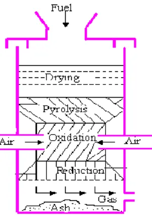
3.1 Fixed Bed Reactors: Fixed bed reactors are used in almost all the chemical plants for one or the other reactions. Packed bed type of reactors is one very popular kind of fixed bed reactors. In our process, we are using the fixed bed to gasify the municipal solid waste. In the way the gasifyers function, they are further divided as updraft and downdraft types of gasifiers[11]. They have been explained below.
An updraft gasifier has clearly defined zones for partial combustion, reduction, and pyrolysis. Air is introduced at the bottom and act as countercurrent to fuel flow. The gas is drawn at higher location. The updraft gasifier achieves the highest efficiecy as the hot gas passes through fuel bed and leaves the gasifier at low temperature. The sensible heat given by gas is used to preheat and dry fuel. Disadvantages of updraft gas proucer are excessive amount of tar in raw gas and poor loading capability. In the updraft gasifier, gas leaves the gasifier with high tar vapour which may seriously interfer the operation of internal combustion engine.
Updraft Gasifier [12] Downdraft Gasifier [12]
Fig 1 Types of Fixed Bed Gasifier
This problem is minimized in downdraft gasifier. In this type, air is introduced into downward flowing packed bed or solid fuels and gas is drawn off at the bottom. A lower overall efficiency and difficulties in handling higher moisture and ash content are common problems in small downdraft gas producers.[12]
7
3.2 Drying: Drying is a mass transfer process consisting of the removal of water or another solvent, by evaporation from a solid, semi-solid or liquid [11]. In some products having relatively high initial moisture content, an initial linear reduction of the average product moisture content as a function of time may be observed for a limited time, often known as a "constant drying rate period". Usually, in this period, it is surface moisture outside individual particles that is being removed. The drying rate during this period is dependent on the rate of heat transfer to the material being dried. Therefore, the maximum achievable drying rate is considered to be heat-transfer limited. In our process, in the Aspen plus process simulator, Rstoic is a block that can be used to simulate a reactor with the unknown or unimportant reaction kinetic and known stoichiometry by specifying the extent of reaction or the fractional component of the key component. Thus in this simulation, it can be used to simulate the drying process (moisture evaporated).
3.3 Pyrolysis: Pyrolysis is a thermochemical decomposition of organic material at elevated temperatures without the participation of oxygen. It involves the simultaneous change of chemical composition and physical phase, and is irreversible. Pyrolysis is a case of thermolysis, and is most commonly used for organic materials, being, therefore, one of the processes involved in charring[11]. Pyrolysis process breaks down charcoal and hydrocarbons by indirect heating. A mixture of gas, liquid and solid products is produced but the proportion of each can be varied depending on the reaction conditions[13]. In our process, the reactor block called Ryield can be used to simulate the pyrolysis, since it is used to model a reactor by specifying yield distribution data or correlation when reaction stoichiometry and kinetics are unknown.
3.4 Combustion: Combustion or burning is the sequence of exothermic chemical reactions between a fuel and an oxidant accompanied by the production of heat and conversion of chemical species. The release of heat can produce light in the form of either glowing or a flame. Fuels of interest often include organic compounds (especially hydrocarbons) in the gas, liquid or solid phase. Complete combustion is almost impossible to achieve. In reality, as actual combustion reactions come to equilibrium, a wide variety of major and minor species will be present such as carbon monoxide and pure carbon (soot or ash). Additionally, any combustion in
8
atmospheric air, which is 78 percent nitrogen, will also create several forms of nitrogen oxides[11]. The combustion section is introduced after the gasifyer and it helps in complete combustion of the unburned carbon to give more flue gas and some residue. This flue gas can either be taken out or be fed back to the gasifyer section to increase its efficiency [1]. Rgibbs unit is used to model this section as it deals with some chemical reactions, thus making the minimization of Gibbs free energy as an important aim.
3.5 Gasification: Gasification is a partial combustion of the solid biomass to give a low to medium heating value fuel gas and an inert residue. Either oxygen enriched air or oxygen may be used with steam added as a reagent and/or temperature control medium. Relatively high temperatures are achieved of 900-1100oC with air, and 1000-1400oC with oxygen. Air gasification is most widely used technology since a single product is formed at high efficiency and without requiring oxygen[10].The resulting gas mixture is called syngas (from synthesis gas
or synthetic gas) or producer gas and is itself a fuel[11]. Gasification as a thermochemical process is defined and limited to combustion and pyrolysis [5]. Rgibbs reactor model can be used for modeling the gasification process as this block will need to minimize Gibbs free energy as well as carry out rigorous reactions and multiphase equilibrium. The main reactions that will be carried out in the gasifier would be :
C + O2 CO2; +393 kJ/mol (1)
C + 1/2O2 CO; +110 kJ/mol (2)
C + CO2 2CO; -173 kJ/mol (3)
C + H2O CO +H2; -132 kJ/mol (4)
CH4 + H2O CO + 3H2; -206 kJ/mol (5)
9
Chapter 4
Technical and Modeling Approach
4.1 Designing the Process Flow Sheet
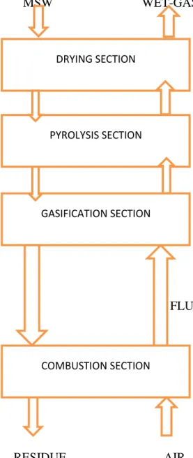
The process flow chart of municipal solid waste gasification in fixed bed can be shown as [5]:
MSW WET-GAS
FLUE GAS
RESIDUE AIR
Fig 2 Schematic design of the Fixed Bed Gasifier DRYING SECTION
PYROLYSIS SECTION
GASIFICATION SECTION
10
MSW is fed from the top into drying section where MSW is dried by the syngas from pyrolysis section; then the dried MSW is pyrolyzed in pyrolysis section. The solid products from pyrolysis section are gasified in gasification section with flue gas from combustion section. In combustion section, the gasified solid products are combusted with the air introduced from the bottom. The combusted products in combustion section are residue and flue gas which is go up into the gasification section.
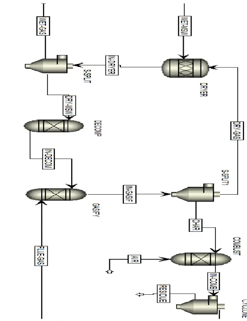
The flowsheet for the above operation has been already made using Aspen Plus.
11
4.2 Modeling of Various Blocks in Aspen Plus
Aspen plus has been widely used in the fields of chemical engineering, oil industry, coal gasification and others. Especially, it has been used in many researches on biomass or MSW gasification[17].It is considered to be an excellent design tool because of its ability in simulating a variety of steady-state processes involving many units[18]. It is based on a minimization of the Gibbs free energy at equilibrium. This simulation is developed under the assumption that the residence time is long enough to allow the chemical reactions to reach an equilibrium state.
The simulations of the MSW gasification process were based on balance of mass and energy, and chemical equilibrium among the overall process. The Aspen system is based on ‘‘blocks’’ corresponding to unit operations as well as chemical reactors, through which most industrial operations can be simulated. It includes several databases containing physical, chemical and thermodynamic data for a wide variety of chemical compounds, as well as a selection of thermodynamic models required for accurate simulation of any given chemical system [19].
In this study, several Aspen plus units were used. The main reactors were simulated by three blocks in Aspen plus: Rstoic, Ryield and Rgibbs. In the Aspen plus process simulator, Rstoic is a block that can be used to simulate a reactor with the unknown or unimportant reaction kinetic and known stoichiometry by specifying the extent of reaction or the fractional component of the key component. Thus in this simulation, it was used to simulate the drying process (moisture evaporated). While pyrolysis is a process of decomposition of the dried MSW, Ryield was used to model this process. Rgibbs block is a rigorous reactor and multiphase equilibrium based on Gibbs free energy minimization [20]. And gasification involves numerous decomposition, recombination and elementary reactions, thus, Rgibbs was preferred because it is based on the minimization of the total Gibbs free energy of the product mixture [17,21]. It can be used
to predict the equilibrium composition of the produced syngas [21]. However, Rgibbs cannot handle char which is referred to as ‘‘non-conventional’’ [21], therefore, the assumption that char contains only carbon was considered. In the combustion process which is also based on the principle of minimization of Gibbs free energy, Rgibbs can also be suitable [20].
12
In these simulations, the ambient temperature was 25o C and the temperature of gasification section was ranged from 500o C to 700o C while that of combustion section was kept at 900o C; system pressure was set at atmosphere pressure; air flow rate depends on the air equivalence ratio which was varied from 0.2 to 0.8; the heat duty was 0 kJ/h in drying section; the solid residue from gasification section consisted of carbon and ash; the characteristics of MSW was an average value of MSW from different provinces in China and the MSW feed rate was 100 kg/h.
13
Chapter 5
Results and Discussion
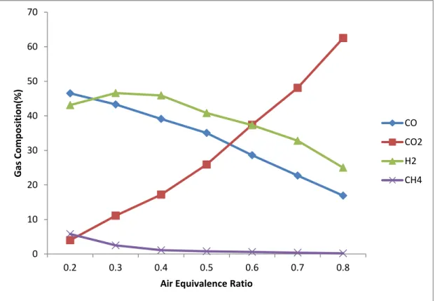
5.1 Effect of Air Equivalence Ratio on Syngas production
In this study, air equivalence ratio represents the ratio of the amount of introducing air to the amount of air needed for complete combustion. Obviously, vary of air equivalence ratio will change the amount of air introduced into the reactor. Therefore, three different reaction conditions can be identified: complete combustion to CO2, complete gasification to CO and
partial combustion (gasification) to CO2 and CO. This ratio has a strong effect on syngas
production. Air equivalence ratio was varied from 0.2 to 0.8 in this simulation. The gasifier temperature was kept at 700o C.
Fig 4 Air Equivalence Ratio v/s Gas Composition Graph
0 10 20 30 40 50 60 70 0.2 0.3 0.4 0.5 0.6 0.7 0.8 Gas Co m p o si tion (% )
Air Equivalence Ratio
CO CO2 H2 CH4
14
CO2 concentration increased significantly (from 5% to 60%) with the increase of air equivalence
ratio while CO showed an inverse trend (from 47% to 15%). This is because the increase of air equivalence ratio (means more oxygen) placed Eq. (1) toward the right. At a higher ratio, CO concentration decreased according to Eq. (1) which prevailed over Eq. (2) with the increase of air equivalence ratio. CH4 concentration decreased as the ratio increased, whilst H2 concentration
decreased according to Eqs. (5) and (6).2 concentration would be higher while CH4 concentration
would be lower because a lower CO concentration would place Eqs. (4)–(6) toward right.
5.2 Effect of Air equivalence Ratio on LHV of Syngas
Effect of air equivalence ratio on LHV of the syngas is presented in Fig. 5. The LHV (kJ/N m3) can be defined as:
LHV=(119950.4 x nH2 + 10103.9 x nCO + 50009.3 x nCH4)/ V (7)
where nCO, nH2 and nCH4 are the molar yields of CO, H2, CH4, respectively, V is the volume of
syngas (m3). From Eq. (7), we can see the LHV is dependent on the concentration of combustible gases. It can be concluded from the discussions of syngas composition above that the concentration of combustible gas decreased with the increase of air equivalence ratio. As a result, LHV of the syngas would decrease as the ratio increased and that trend can be found in Fig. 5.
Fig 5 Air Equivalence Ratio v/s LHV Graph
0 1000 2000 3000 4000 5000 6000 7000 8000 9000 0 0.2 0.4 0.6 0.8 1 LH V(K j/m 3)
Air Equivalence ratio
15
5.3 Effect of Air Equivalence Ratio on Carbon Conversion and Heat Conversion Efficiency
The Carbon conversion efficiency is given as :
q=m1/m2; (8)
q is the carbon conversion of MSW, m1 is the weight of carbon in the syngas, kg, m2 is the weight of carbon of MSW fed into the system in kg.
Heat conversion efficiency is given by :
r= (Q x V)/m(MSW); (9)
Q is the LHV of the syngas (dry) yield in the gasifier, kJ/Nm3, and m(MSW) is the weight of MSW fed into the system in kg. V is the volume of syngas produced(m3).
Fig 6 Air Equivalence Ratio v/s Carbon and Heat Conversion Efficiency
0 0.2 0.4 0.6 0.8 1 1.2 0 1000 2000 3000 4000 5000 6000 7000 8000 0.2 0.3 0.4 0.5 0.6 0.7 0.8 Car b o n Co n ve rsi o n E ff ic ie n cy H e at co n ve rsi o n (K j/m 3)
Air Equivalence Ratio
r(heat conversion efficiency) kJ/m3
16
As shown in Fig. 6, carbon conversion increased and kept constant when it reached the maximum value as the ratio increased.Heat conversion efficiency decreased with the increase of air equivalence ratio. A same difference can be found at a lower ratio that heat conversion efficiency.
5.4 Effect of Gasification Temperature on Syngas Production
The gasification temperature influences the equilibrium of the chemical reactions [22]. In this study, effect of flue gas and gasification temperature on syngas production at an air equivalence ratio of 0.2 was discussed. As shown in Fig. 7, CO concentration increased with the increase of gasification temperature while CO2 concentration followed an opposed trend. CH4 concentration
decreased slightly as the gasification temperature increased, while H2 concentration increased
slightly with the increase of gasification temperature.
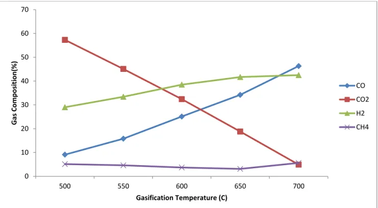
Fig 7 Gasification Temperature v/s Gas composition
0 10 20 30 40 50 60 70 500 550 600 650 700 Gas Co m p o si tion (% ) Gasification Temperature (C) CO CO2 H2 CH4
17
These trends can be attributed to the chemical reaction laws: higher temperatures favoured the products in endothermic reactions, and favoured the reactants in exothermic reactions. Therefore, with the increase of temperature, the decrease of CH4 concentration could be ascribed
to the endothermic reaction (5) and (6). The increase of H2 concentration could be explained by
the endothermic reaction (4)–(6), and CO concentration would increase because endothermic reaction (3)– (5) are more dominant than exothermic reaction Eq. (2). Although endothermic reaction Eq. (6) releases 22 (and the CO2 concentration should increase), the CO2 concentration
decreased as the temperature increased. This is because endothermic reaction Eq. (3) was more dominant, placing the reaction toward the right, and resulting in the increase of CO and decrease of CO2 as the temperature increased.
5.5 Effect of gasification Temperature on LHV
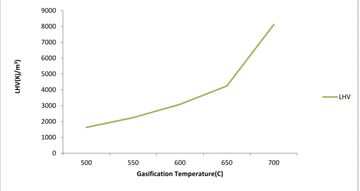
Fig. 8 shows that the LHV increased with the increase of gasification temperature. The highest LHV was about 8000 kJ/m3 at 700o C.
Fig 8 Gasification Temperature v/s Gas composition
0 1000 2000 3000 4000 5000 6000 7000 8000 9000 500 550 600 650 700 LH V(K j/m 3) Gasification Temperature(C) LHV
18
5.6 Effect of Gasification temperature on Heat Conversion and Carbon Conversion Efficiency
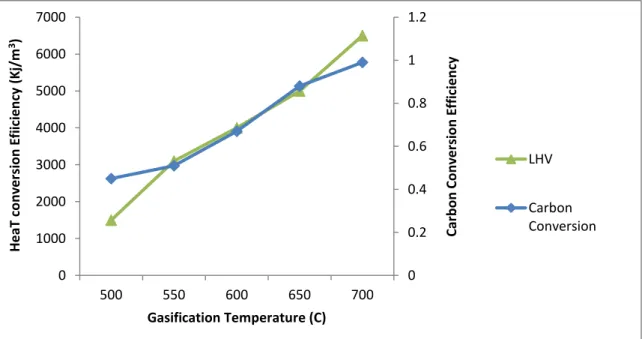
Increasing gasification temperature led to an increase of heat conversion efficiency and carbon conversion.
Fig 9 Gasification Temperature v/s Heat and Carbon Conversion Efficiency
These trends can be explained by that the increase of gasification temperature in both types would place the endothermic reaction (3)–(5) toward right which result in the increase of carbon conversion and heat conversion efficiency. And with the increase of gasification temperature, the introduction of flue gas (CO2) would result in more CO according to Eq. (3) that means higher
carbon conversion and heat conversion efficiency.
0 0.2 0.4 0.6 0.8 1 1.2 0 1000 2000 3000 4000 5000 6000 7000 500 550 600 650 700 Car b o n Co n ve rsi o n E ff ic ie n cy H e aT c o n ve rsi o n E fi ic ie n cy (K j/m 3) Gasification Temperature (C) LHV Carbon Conversion
19
CONCLUSION
1. The Air equivalence ratio was found to be highly affecting the output gas composition and LHV. The best ratio was determined to be 0.2.
2. As we increase the air equivalence ratio, the amount of CO2 was seen to increase, which
has no significant heating value.
3. The gasification temperature was a major factor in syngas production. The CO2 gas
decreased as well as the CO and H2 gas showed significant increase. But the amount of
CH4 was more or less constant.
4. The carbon conversion efficiency was seen to be almost constant at all equivalence ratio, but the heat conversion efficiency decreased with increasing air equivalence ratio.
5. The gasification temperature also had an effect on LHV of the gas as well as on its Carbon conversion and Heat conversion efficiencies. They all seemed to respond well to the increasing temperature of gasification.
20
References:
[1] Porteous A., Energy from waste incineration — a state of the art emissions review with an emphasis on public acceptability. Appl Energy 2001;70:157–67.
[2] McKay G., Dioxin Characterisation, formation and minimisation during municipal solid waste (MSW) incineration: review. Chem Eng J 2002;86:343–68.
[3] Calaminus B, Stahlberg R., Continuous in-line gasification/vitrification process for thermal waste treatment: process technology and current status of projects. Waste
Manage 1998;18(6–8):547–56.
[4] Bridgwater T., Review biomass for energy. J Sci Food Agric 2006;86:1755–68.
[5] Warnecke R.,Gasification of biomass: comparison of fixed bed and fluidized bed gasifier. Biomass Bioenergy 2000;18(6):489–97.
[6] Kyriakos M, Enzo M., Energy from biomass and waste: the contribution of utility scale biomass gasification plants. Biomass Bioenergy 1998;15(3):195–200.
[7] Beenackers AACM., Biomass gasification in moving beds, a review of European technologies. Renew Energy 1999;16:1180–6.
[8] Belgiorno V, De Feo G, Della Rocca C, Napoli RMA., Energy from gasification of solid wastes. Waste Manage 2003;23:1–15.
[9] Quaak P, Knoef H, Stassen H., Energy from biomass: a review of combustion and g gasification technologies. World Bank technical paper no. 422. Energy series; 1999.
[10] Bridgwater AV., Catalysis in thermal biomass conversion. Appl Catal A-Gen 1994;116(1–2):5–47.
21 [11] en.wikipedia.com
[12] http://cturare.tripod.com/gas.htm
[13] Barker S.N., Gasification and Pyrolysis-Routes to competitive electricity from biomass in the UK, Elsevier Science ltd (1996), Britain.
[14] http://www.epa.gov/osw/nonhaz/municipal/
[15] http://www.eia.gov/cneaf/solar.renewables/page/mswaste/msw.html
[16] http://edugreen.teri.res.in/explore/solwaste/types.htm
[17] Nikoo MB, Mahinpey N. Simulation of biomass gasification in fluidized bed reactor using ASPEN PLUS. Biomass Bioenergy 2008;32(12):1245–54.
[18] Sotudeh-Gharebaagh R, Legros R, Chaouki J, Paris J. Simulation of circulating fluidized bed reactors using ASPEN PLUS. Fuel 1998;77(4):327–37.
[19] Zheng LG, Furimsky E. ASPEN simulation of cogeneration plants. Energy Convers Manage 2003;44(11):1845–51.
[20] Jannelli E, Minutillo M. Simulation of the flue gas cleaning system of an RDF incineration power plant. Waste Manage 2007;27(5):684–90.
[21] Zhao YH, Hao W, Xu ZH. Conceptual design and simulation study of a cogasification technology. Energy Convers Manage 2006;47(11–12):1416–28.
[22] Cimini S, Prisciandaro M, Barba D. Simulation of a waste incineration process with flue-gas cleaning and heat recovery sections using Aspen Plus. Waste Manage 2005;25(2):171–5.