University of Wollongong
Research Online
Australian Institute for Innovative Materials - Papers
Australian Institute for Innovative Materials
2014
Force control of a tri-layer conducting polymer
actuator using optimized fuzzy logic control
Mehmet Itik
Karadeniz Technical University (Turkey)
Mohammadreza Sabetghadam
Karadeniz Technical UniversityGursel Alici
University of Wollongong, [email protected]
Research Online is the open access institutional repository for the University of Wollongong. For further information contact the UOW Library: [email protected]
Publication Details
Itik, M., Sabetghadam, M. & Alici, G. (2014). Force control of a tri-layer conducting polymer actuator using optimized fuzzy logic control. Smart Materials and Structures, 23 (12), 125024-1-125024-10.
Force control of a tri-layer conducting polymer actuator using optimized
fuzzy logic control
Abstract
Conducting polymers actuators (CPAs) are potential candidates for replacing conventional actuators in various fields, such as robotics and biomedical engineering, due to their advantageous properties, which includes their low cost, light weight, low actuation voltage and biocompatibility. As these actuators are very suitable for use in micro-nano manipulation and in injection devices in which the magnitude of the force applied to the target is of crucial importance, the force generated by CPAs needs to be accurately controlled. In this paper, a fuzzy logic (FL) controller with a Mamdani inference system is designed to control the blocking force of a trilayer CPA with polypyrrole electrodes, which operates in air. The particle swarm optimization (PSO) method is employed to optimize the controller's membership function parameters and therefore enhance the performance of the FL controller. An adaptive neuro-fuzzy inference system model, which can capture the nonlinear dynamics of the actuator, is utilized in the optimization process. The optimized Mamdani FL controller is then implemented on the CPA experimentally, and its performance is compared with a non-optimized fuzzy controller as well as with those obtained from a conventional PID controller. The results presented indicate that the blocking force at the tip of the CPA can be effectively controlled by the optimized FL controller, which shows excellent transient and steady state characteristics but increases the control voltage compared to the non-optimized fuzzy controllers.
Keywords
force, logic, optimized, fuzzy, actuator, polymer, conducting, layer, tri, control
Disciplines
Engineering | Physical Sciences and Mathematics
Publication Details
Itik, M., Sabetghadam, M. & Alici, G. (2014). Force control of a tri-layer conducting polymer actuator using optimized fuzzy logic control. Smart Materials and Structures, 23 (12), 125024-1-125024-10.
Force control of a tri-layer conducting polymer
actuator using optimized fuzzy logic control
Mehmet Itik1, Mohammadreza Sabetghadam1, Gursel Alici2,3
Department of Mechanical Engineering, Karadeniz Technical University, Trabzon, Turkey, 61080
2
School of Mechanical, Materials and Mechatronic Engineering, University of Wollongong, NSW 2522, Australia.
3
ARC Centre of Excellence for Electromaterials Science, Intelligent Polymer Research Institute, AIIM Faculty, Innovation Campus, University of Wollongong, NSW 2500, Australia
Abstract
Conducting polymers actuators (CPAs) are potential candidates for replacing conventional actuators in various fields such as robotics and biomedical engineering due to their advantageous properties including low cost, light weight, low actuation voltage and biocompatibility. As these actuators are very suitable for use in micro-nano manipulation and injection devices, where the magnitude of the force applied to the target is of crucial importance, the force generated by CPAs needs to be accurately controlled. In this paper, a fuzzy logic (FL) controller with Mamdani inference system is designed to control the blocking force of a trilayer CPA with polypyrrole electrodes, which operates in air. A Particle Swarm Optimization (PSO) method is employed to optimize the controller’s membership function parameters, and therefore to enhance the performance of the FL controller. An Adaptive Neuro-Fuzzy Inference System model which can capture the nonlinear dynamics of the actuator is utilized in the optimization process. The optimized Mamdani FL controller is then implemented on the CPA experimentally and their performance are compared with a non-optimized fuzzy controller as well as with those obtained from a conventional PID controller. The results presented indicate that the blocking force at the tip of the CPA can be effectively controlled by the optimized FL controller which shows excellent transient and steady state characteristics, and decreases the control voltage considerably compared to the PID and non-optimized fuzzy controllers.
1. Introduction
Conducting polymer actuators (CPAs) are promising replacements for conventional actuators such as electric motors, hydraulic and pneumatic actuators due to their unique properties such as light weight, biocompatibility, compactness and low power consumption [1-8]. Especially the ones that can operate in air can be used in various cutting-edge applications in biotechnology, robotics and mechatronics [9-12]. In order for CPAs to be fully utilized in the applications, their tip displacement and/or blocking force response should be precisely controlled using either open-loop or feedback control methods. Different control methods have been proposed to obtain a desired tip displacement response from CPAs some of which are a conventional PID controller [4], a robust adaptive controller to overcome time varying actuation behavior of CPAs due to solvent evaporation during the long-time operation in air [13], a repetitive controller to precisely track the repeating trajectories [14], an adaptive sliding mode controller to obtain robust performance in the presence of parametric uncertainties and unmodeled disturbances [15].
In addition to controlling the tip displacement of trilayer bender type CPAs, their blocking force must be controlled in applications such as micro-nano manipulation and cell-injection devices since the target may be damaged due to an excessive force applied by the actuator. Although there are many work in the literature focused on controlling the tip displacement of CPAs, there is no reported work on the control of blocking force for this class of actuators. This may be due to the fact that the models for the force output of electroactive polymers are either quasi-static models which cannot be used in controller design [16, 17] or not suitable for the trilayer bender type CPAs operating in air [18]. As a dynamic force model for trilayer CPAs does not exist, one possible way is to design linear controllers by using a model obtained by linear system identification. However, using linear models in designing controllers for either CPAs or
other ionic polymer actuators may result in poor performance due to their nonlinear and uncertain dynamics.
Fuzzy logic (FL) controllers can be used to control polymer actuators as there are difficulties in deriving their precise mathematical models [19,20]. A disadvantage of the FL control is that designing an effective rule base requires experience, intuition and trial-and-error methods which make it difficult to optimize performances especially when the dimensions of the rule base become larger [20]. In order to overcome the problem of manual tuning of the membership functions and parameters of FL controllers, heuristic algorithms can be utilized [21,22]. However, this also requires a model of the system for optimization process. Neuro-fuzzy methods can be used to obtain data driven models that capture nonlinearities in system dynamics. They can be used for either controller design or optimization of an existing controller. Adaptive neuro-fuzzy inference system (ANFIS) method was also used as a controller for the tip displacement of both ionic polymer metal composite (IPMC) actuators [20] and trilayer bender type CPAs [19]. Recently, a data driven ANFIS model was used to design a predictive controller for a high-speed electric multiple unit due to its feature for capturing nonlinearities very effectively [23].
In this paper, we propose a FL controller in order to obtain a desired force response at the tip point of a trilayer CPA operating in air. The FL controller has a Mamdani type inference system with 49 rules. One of the main advantages of the Mamdani type FL controller is that it does not require a model of the actuator. However, its major drawback is that the parameters of the controller i.e. the membership functions are constructed based on a trial and error method which makes it a very time consuming procedure. To overcome this problem, the Particle Swarm Optimization (PSO) algorithm is used to fine tune and optimize the parameters of the antecedent and consequent membership functions used in the controller. Optimization is done offline using a nonlinear force model of the actuator which is obtained by using ANFIS) method. Both FL controller and its optimized version are applied to the actuator to demonstrate the efficacy of the force control method implemented in this study. In order to make a
comparison, a PID controller is designed whose parameters are also fine-tuned by using the PSO algorithm and implemented on the actuator experimentally.
The rest of the paper is organized as follows. In Section 2, the tri-layer CPA is introduced and its operation mechanism is described. A background on FL Control is given and controller design procedure is explained in Section 3. In Section 4, the PSO method and its implementation for the FL controller is discussed in details. In Section 5, experimental results are provided. Summary and concluding remarks are presented in the last section.
2. Conducting Polymer Actuator and its Dynamics
2.1. CPA Actuator
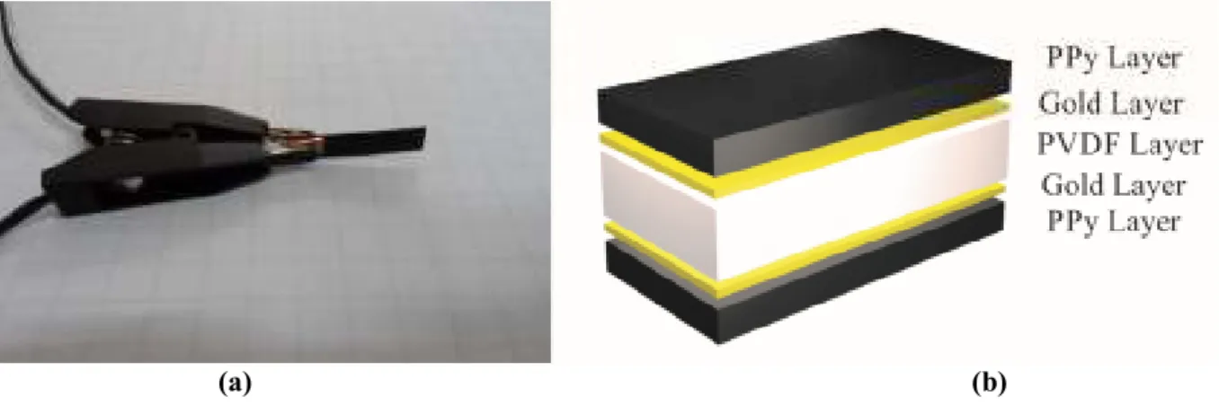
The trilayer conjugated polymer actuator used in this study which is shown in Fig. 1a has the dimensions of 14 mm × 5 mm × 0.17 mm. It consists of three main layers as shown in Fig. 1b. On the outer surfaces, there are two PPy layers, each of which has a thickness of 30 µm. They are the electroactive components of the actuator. Between them, there is an amorphous, porous nonconductive layer with a thickness of 110 µm that is made of Polyvinylidene Difluoride (PVDF). Its main duty is to hold the liquid electrolyte that supplies ions which are responsible for the actuation. The PVDF layer is coated with 0.2 µm thick gold particles on both sides to provide a conductive surface on which the PPy electrodes can be electrochemically deposited [24]. The electrolyte consists of lithium triflouromethanesulfonimide
+
(a) (b)
Figure 1. Conducting Polymer actuator: (a) optical image and (b) schematic view of the PPy actuator. The operation principle of CPAs is related to the electronic structure of them, which allows electrons to be removed via electrochemical oxidation [19]. When an adequate voltage is passed through the PPy layers on the actuator, the PPy layer on the anode side is oxidized, while that on the cathode side is reduced, as illustrated below;
- Oxidation + -
-Reduction
PPy+TFSI ←→ PPy TFSI +e (1)
Figure 2. Actuation mechanism of the trilayer CPAs.
To maintain charge neutrality within the PPy layers, TFSI- anions will be absorbed by the positively charged PPy electrode. Hence this layer expands. While the anions (TFSI-) are expelled from the negatively charged electrode, the reduction of the PPy generates a volume contraction [24]. As a result,
the expansion-contraction triggered by the redox process causes the cantilevered structure to bend towards the negative electrode as illustrated in Fig. 2.
3. Fuzzy Logic Control Design for Trilayer CPAs
FL controller provides an algorithm which can convert the linguistic rules in terms of “if-then” expressions based on expert knowledge into an automatic control strategy. A FL controller typically includes four major units: the fuzzifier, which converts crisp input data into a fuzzy term set; the fuzzy rule base, which contains fuzzy rules describing how the fuzzy system acts; the fuzzy inference engine, which is responsible for approximate reasoning by associating input variables with fuzzy rules; and the defuzzifier, which turns fuzzy output of the FL controller to a crisp value for the actual system input over the target [25]. When designing a FL controller, the selection of fuzzy sets of linguistic variables, the shapes of membership functions, the fuzzy rule base, the inference mechanism, and the defuzzification method are considered as design parameters all of which have influence on control performance. Therefore, it is the designer’s duty to choose these factors with care by observing the system’s behavior and using trial and error method, to achieve the optimum design for FL controller.
A FL controller is preferred especially when the processes are too complex for analysis by quantitative techniques, or when the available sources of information are interpreted imprecisely, or indeterminately [26]. Modeling of CPAs has not reached the accuracy desired. As a result, proposed models cannot represent all nonlinearities and uncertainties in the behavior of these actuators. FL controllers’ non-model-based design feature makes them a promising control method for precise positioning of CPAs compared with model based controllers [19]. Moreover, using Neuro-Fuzzy based models which can consider the nonlinearities of the systems can further improve the performance of the Fuzzy controllers if they are incorporated into the design process. Therefore, we first propose a Mamdani Fuzzy Logic inference system to control the blocking force of the CPA.
The design procedure for a fuzzy logic controller is based on heuristic information obtained from the dynamic behavior of the system which is the trilayer bender type CPA in this work [26,27,28]. Choosing the inference system determines the format of the fuzzy rules. Mamdani reasoning system for which the fuzzy rules are defined as
: ( 1, 2,..., )
i i i i
R IF x is A AND y is B THEN z is C for i= k (2)
where k is the number of rules,
x
andyare the input variables, z is the output variable, Ai,Biand Ci arethe linguistic values of x,yand z, respectively. The rest of the design is comprised of four steps which are given as follows.
Step 1: After picking the reasoning system, the initial step to develop a fuzzy controller is to choose input and output variables. The input variables are error, e(t) and its time derivative, d e t( ). The output of the fuzzy controller is the actuation voltageu t( ). The error, e(t) is defined as the difference between the desired tip displacement of the actuator, yd and its measured displacement,ya
Step 2: Appropriate membership functions should be chosen to fuzzify the crisp values of each input and
output variable. Selection of number and type of the membership functions is based on trial and error. Seven triangular membership functions are considered for each input and output variable. The triangular membership function is i i i A i i i i x a c x (x) max min , ,0 b a c b µ = −− −− 3
where parameters ai and ci locate the feet of triangular fuzzy setAi; bi is the peak of the triangle and
x
is the crisp value. Fuzzy sets are labeled with linguistic terms as negative big (NB), negative medium
(NM) negative small (NS), zero (ZZ), positive small (PS), positive medium (PM), positive big
(PB).
Step 3: The rule base of the fuzzy controller, which consists of 49 rules, are determined and summarized
in Table 1.
Table 1. Rule base of Mamdani fuzzy controller for CPA.
Step 4: Defuzzification of the output value calculated during the fuzzy reasoning is performed in this step
to obtain their crisp values. We use a centroid defuzzification technique given by
* ( ) ( ) i i z z dz z z dz µ µ =
∫
∫
4where z* is the defuzzified output,
i
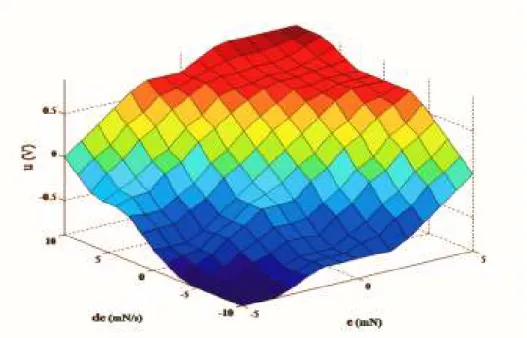
µ is the aggregated membership degree and z is the output value. Output surface of Mamdani fuzzy controller is illustrated in Fig. 3.
U de NB NM NS ZZ PS PM PB e NB NB NB NB NM NS NS ZZ NM NB NB NM NM NS ZZ PS NS NM NM NS NS ZZ PS PM ZZ NM NM NS ZZ PS PM PM PS NM NS ZZ PS PM PM PB PM NS ZZ PS PM PM PM PB PB ZZ PS PM PM PM PB PB
Figure 3. Output surface of Mamdani fuzzy logic controller.
4. Fuzzy membership function tuning with Particle Swarm Optimization (PSO):
4.1. PSO Background
PSO is an evolutionary computation method introduced by Kennedy and Eberhart which is inspired by simulating the unpredictable choreography of a bird flock [29]. The logic behind the PSO is that each member of the swarm, called a particle, follows the best performing particle (leader) while searching the best experience each particle has. To implement the PSO algorithm for optimization problems, the following procedure should be considered [29]:
1) Initialize a swarm of particles with randomly assigned positions and velocities. Select the dimension dof each particle based on the number of parameters to be optimized.
2) Evaluate the desired optimization fitness function for each particle in dvariables.
3) Compare the fitness value of the particle with particle’s best experience, pbest. If the present value is better than pbest then take the current value as pbest and assume its location as the
4) Compare the fitness results with swarm’s overall previous best, gbest. Replace gbest with particle’s array index and value if it’s better thangbest.
5) Change the velocity and position of the particle respectively using the following equations :
1 1 2 2 ( 1) * V ( ) * ( (t)) * ( ( )) id id id id gd id V t+ =w t +c r p −x +c r p −x t (5) ( 1) ( ) ( 1) id id id x t+ =x t +v t+ (6)
where vid(t+1) and vid( )t are the updated and current particles velocities, xid(t+1) and xid( )t are the updated and current position of particles, respectively.c1 and c2 are positive constants while r1
and r2 normalized random numbers between 0 and 1.pid and pgd represent pbest and gbest,
respectively in each iteration.
6) Go back to step 2 until the criterion is met. Termination is usually based upon a sufficiently good fitness or a maximum number of iterations
4.2. ANFIS model:
In order to optimize the FL controller for the CPA, one needs to use a pre-identified mathematical model. A better performance in FL controllers would be expected when they are optimized by using a nonlinear model which captures the dynamic behavior of the actuator better. Since a nonlinear force model does not exist for CPAs, we obtain a data driven nonlinear model obtained via ANFIS method.
ANFIS is a combination of fuzzy inference system’ (FIS) interpretability and neural networks’ adaptability which overcomes limitations of design process of FIS by tuning it with input-output data [26]. FIS takes the linguistic expressions and trains them by empirical data using learning algorithm of neural networks [30]. Intelligent architecture of ANFIS consists of a Takagi-Sugeno (T-S) type fuzzy inference system implemented in the framework of an adaptive neural network. Here, T-S type FIS is considered with two inputs x1=u k( −1), x2 =y k( −1) and one outputy k( ). Applying the pre-designed
FL controller to the CPA, the required data is collected for training the ANFIS model. The dynamic model of the CPA is then expressed in terms of the fuzzy inference rules,
R
i [23]:1 2 1 2 : if ( 1) is and ( 1) is then ( ) ( 1) ( 1) ; ( 1, 2,..., ) i i i i i i i R y k A u k A y k
θ
y kθ
u kξ
i n − − = − + − + = (7)where n denotes the number of fuzzy rules and
{
A A1i, 2i}
denotes the fuzzy linguistic values. Consequent parts of T-S type fuzzy rules (7) are linear equations in two input variables,{
θ θ
1i, 2i}
and a constant,ξ
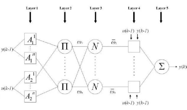
i which are determined by ANFIS while it is being trained. ANFIS consists of five layers as shown in Fig. 3.Figure 3. ANFIS Structure
In each layer, there are nodes with particular features. Circles represent fixed nodes, while squares indicate adaptive nodes. A brief explanation for the layers of ANFIS is given as follows [23,30]:
Layer 1: All nodes in this layer are adaptive and generate a membership degree for each input variable. The membership functions i
j A
µ
of fuzzy set Aij are defined by the Gaussian membership functions:(
)
2 2 exp ; ( 1, 2,..., ; 1, 2) 2 i j j ij A ij x c i n jµ
σ
− = − = = (8)where xj(j=1, 2) is the input variable and the set
{
cij,σ
ij}
represents the center and width of the Gaussian membership functions.Layer 2: All nodes in this layer are fixed nodes, each represents a fuzzy rule. Nodes multiply the incoming signals from antecedent fuzzification layer and calculate the firing strength of rules
ω
i using the node function below:1i 2i
i A A
ω
=µ µ
(9)Layer 3: Fixed nodes in the third layer are responsible for computing the normalized firing strength of fuzzy rules calculated in the previous layer. Normalized firing strength
ω
i is the ratio of firing strength ofeach rule to the sum of the firing strength of all rules;
1 Σ i i n i i
ω
ω
ω
= = (10)Layer 4: Adaptive nodes in this layer take the normalized firing strength value of each fuzzy rule and multiply it by consequent part of each fuzzy rule. The node function of this layer is
1 2
. ( ) i ( 1) i ( 1)
i y ki i y k u k i
ω
=ω θ
− +θ
− +ξ
(11)Layer 5: In the last layer, there is a single fixed node which is responsible for computing the overall output:
1 1 2 1 ( ) ( ) ( 1) ( 1) n i i i n i i i i i y k y k y k u k ω ω θ θ ξ = = = = − + − +
∑
∑
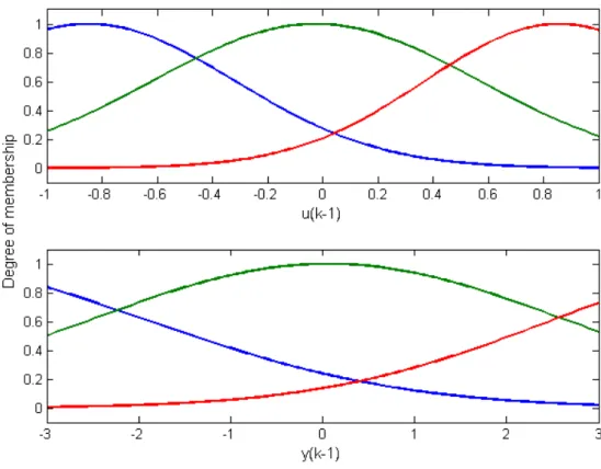
(12)ANFIS structure used in this study has been created in MATLAB and it runs a hybrid learning algorithm which comprised of least square approximation and back propagation methods to accomplish training process. The details of the algorithm can be found in [30]. For the nonlinear identification of the actuator’s behavior, we used a PBRS signal with 3 mN amplitude and 0.5 Hz frequency as a reference signal in the closed-loop form. The sampling frequency for the data acquisition was selected as 100 Hz for 100 seconds. First 5000 samples of the data collected were used for training and the last 5000 were used for validation. The fuzzy model was then developed in ANFIS using 50 training epochs and different combinations of membership functions in terms of type and number which resulted in a system with three fuzzy sets for each input with Gaussian bell membership functions which is given in Fig. 4.
4.3. Fuzzy membership function tuning with PSO:
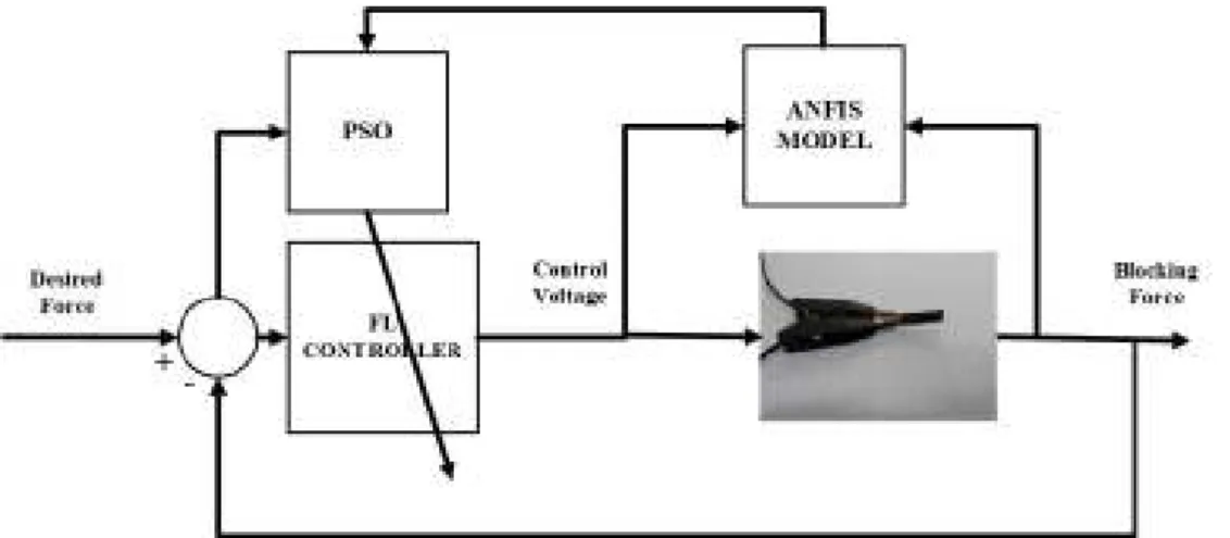
FL controller design is based on the expert knowledge and heuristic information. Constructing the rule base of the controller relying on heuristic information is easier than selecting suitable parameters for fuzzy membership functions. These parameters define the geometrical specification of fuzzy membership functions which are the place of each foot and peak for a triangular kind. Obtaining such parameters by experimentation and trial-error approach is a tedious task. Therefore, it is possible to use heuristic algorithms such as PSO, genetic algorithm, and cuckoo method as an optimization method to search for the parameters of fuzzy membership functions and tune them to achieve the best controller performance [21, 22]. Application of PSO to optimize the fuzzy controller is shown schematically in Fig. 5. The model used here for optimization procedure is the one obtained by ANFIS.
Figure 5. The proposed PSO membership function tuning method.
Each particle used in the PSO represents the parameters of input and output membership functions. Since the goal of the PSO is to minimize the tracking error, Integral of Time Absolute Error (ITAE) performance index was chosen as the objective function. ITAE performance index can be calculated as
0 (t)
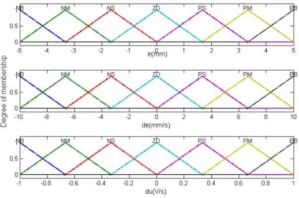
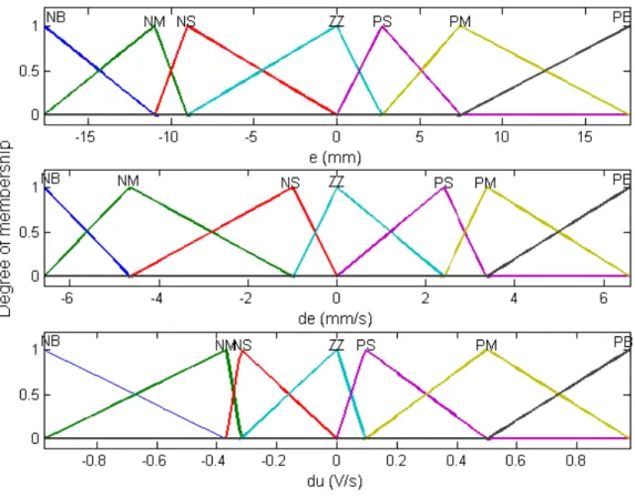
As there are two inputs and one output variables in the proposed FL controller, each with seven triangular membership functions, 63 dimensions are required for every particle to tune the input and output membership functions. However, as a feet position also corresponds to the peak position of the following membership function, the parameter numbers to be optimized reduce to 15. The PSO parameters used in this study are shown in the Table 2. The membership functions before and after optimization are given Fig 6 and Fig. 7, respectively.
Table 2. PSO parameters for tuning membership functions of FL controller
Parameter Value 1
C
1 2C
3 Inertiaw
factor 0.5 Number of particle 20Number of searching iterations 50
Figure 7. Fuzzy sets of the input and output variables for optimized fuzzy controller
5. Experimental setup and results:
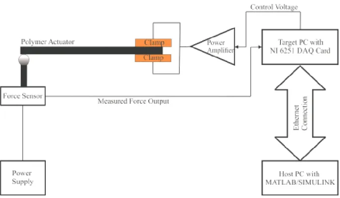
The experimental setup to implement the designed Fuzzy Logic controllers for controlling the force output of the CPA is illustrated in Fig. 8. The force generated at the tip of the cantilevered PPy actuator was measured via a Millinewton (IPR EPFL, Switzerland) force sensor. Employing xPC Target platform, an analog signal supplied by the force sensor was acquired and transferred to MATLAB/Simulink environment by National Instruments NI 6251 data acquisition card. The target PC, through which the experiments were performed, has a 1 GB RAM and Intel P4 processor. It runs in MS-DOS environment where the controller algorithms are compiled as C codes. As a result, the control algorithm works fast
Figure 8. Experimental setup
In micro/nano gripping and cell injection applications where CPAs are very suitable to provide the required manipulation, it is important to keep the desired force at the tip of the actuator in a desired set point. In evaluating the designed controller performance for such problems, it is suitable to use a step reference as a test input for the closed loop control system. Hence, we used step reference inputs with two different amplitudes which are 1 mN and 3 mN. To make a fair comparison, a PID controller was fine-tuned via the PSO method using an identified transfer function model. The gains of the PID controller are obtained as KP=0.47,KI =0.66,KD=0.005.
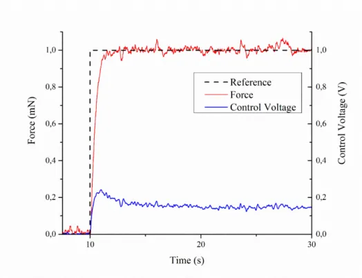
We first implemented the non-optimized and optimized FL controllers and then a PID controller was also implemented. The actuator’s force output and the calculated control voltage upon the implementation of Mamdani type fuzzy controller is given in Fig. 9. The Mamdani fuzzy controller performed quite well in terms of both transient and steady-state characteristics. Moreover, the maximum control voltage of the
Mamdani type fuzzy controller is approximately 0.25 V which is well-below the safe operation limit of the CPA.
Figure 9. Force response of the actuator to a step of 1 mN under FL controller
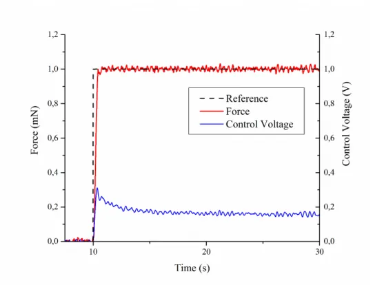
The optimized controller was then implemented experimentally. Its response is illustrated in Fig. 10. An improvement is visible in its transient response under the optimized FL controller. Finally, the PID controller based on an identified model of the CPA was implemented for 1 mN step input for comparison. The response of the actuator under the PID controller is shown in Fig. 11.
Figure 10. Force response of the actuator to a step of 1 mN under optimized FL controller
As shown in Figures 10-12, all controllers are successful in controlling the force output of the actuator and reaching the desired final value. However, their performance in terms of step response characteristics are different. Step response characteristics of the actuator under all controllers are summarized in Table 3.
Table 3. Performance of the controllers to 1-mN step response
Control Method Rise Time
[s] Settling Time [s] Overshoot [%] Fuzzy Logic 0.79 1.03 0
Optimized Fuzzy Logic 0.23 0.33 0
PID 0.53 4.10 9
Table 4 shows the rise time, settling time and overshoot of the actuator’s response to a 1 mN step reference. FL controller performs better than PID controller since there is no overshoot in its response, besides it achieves a 4 fold improvement in settling time. The optimized FL controller has no overshoot, and has the shortest rise time and settling time among the other controllers. A performance improvement of 2-3 times for rise time and 3-12 times for settling time compared to FL and PID controllers, when the FL controller is optimized. When we check the required control voltage to reach and stay at the desired set point, it is seen that the voltage consumption of the non-optimized FL controller is the lowest. Optimizing the FL controller results in improvement in the transient performance of the actuator but increases the required control voltage. However, all three controllers’ voltage requirements were well below the limit to prevent the damage to the actuator.
A 3-mN step reference was also applied to the actuator to examine its performance under a more aggressive reference signal. The force generated at the tip of the actuator and the calculated control voltage by the fuzzy logic, optimized fuzzy logic and PID controllers are illustrated in the Figures 12-14 respectively.
Figure 12. Force response of the actuator to 3 mN step reference under FL controller
Figure 14. Force response of the actuator to 3 mN step reference under PID controller
The sudden jump in the step reference yields an initial high amplitude voltage spike in the control input which makes the actuator to rapidly produce a force output to reach to the desired set point. This high voltage may harm the actuator unless carefully treated. After this initial spike, the control voltage reduces to a constant value which keeps the force output of the actuator at the steady state position. It is seen from Figure 14 that the maximum control voltage of the PID controller is increased when 3 mN step input is applied to the actuator. The control voltage becomes nearly 1.25 V which is very close to the maximum safe voltage that can be applied to the actuator. Hence, the set point was kept below 3 mN to avoid damaging the actuator. The step response performances of all controllers are compared for a 3 mN step input in Table 4.
Table 4. Performance of the controllers to 3-mN step response
Control Method Rise Time
[s] Settling Time [s] Overshoot [%] Fuzzy Logic 1.03 1.57 0
Optimized Fuzzy Logic 0.51 0.72 0
PID 0.57 4.70 7
Table 4 shows that the FL controller improved settling time by decreasing it to one third of the PID controller’s settling time. Moreover, no overshoot is observed in the actuator’s performance with the FL controller while the PID controller’s response has 7% overshoot which is not negligible. The optimized FL controller has the fastest rise time and settling time without any overshoot which again makes it the most promising control technique compared to the other two control techniques.
Repeatability:
In order to prove the repeatability of the experiments and robustness of the designed controllers, we applied them on a second CPA sample whose geometrical specifications were the same as the first one. Again two step signals with varying amplitudes of 1 mN and 3 mN were used as the command inputs. The second actuator’s step response characteristics are listed in Tables 5-6. For the sake of brevity, the responses of the second sample are not presented here.
Table 5. 1-mN step response performance of the controllers on the second actuator
Control Method Rise Time
[s] Settling Time [s] Overshoot [%] Fuzzy Logic 0.96 1.20 0
Optimized Fuzzy Logic 0.23 0.34 0
Table 6. 1-mN step response performance of the controllers on the second actuator
Control Method Rise Time
[s] Settling Time [s] Overshoot [%] Fuzzy Logic 1.48 2.48 0
Optimized Fuzzy Logic 0.96 1.25 0
PID 0.59 8.70 7.5
A noticeable trend was obtained in the results of the second sample’s performance with the proposed controllers. As in the first sample, the second actuator exhibits no overshoot under the FL controller and its optimized version. By comparing the step response results of this actuator with those of the first CPA sample, it can be understood that the second actuator is constantly slower in rise time and settling time. All the controllers show a repeatable performance and the optimized FL controller showed a significant performance improvement in the blocking force response of the CPA.
Robustness to Actuator Drift
To examine the designed controllers’ performance in dealing with the drift problem associated with this class of actuators, a 1 mN step response test is performed for 600 s which is 10 times longer than the previously conducted experiments in this study. The results of the tests are shown in Figure 15. All controllers are successful in compensating for the actuator’s drift which is due to feedback control rather than the control methodologies implemented.
Figure 15. Actuator’s long time response to a 1 mN step under different control schemes
6. Conclusion
In this study, Mamdani fuzzy inference system was employed to design a FL controller to control the force output of a trilayer CPA with PPy electrodes. To the best of our knowledge, this is the first time to report on the blocking force control of the conducting polymer actuators. The membership functions of the pre-designed FL controller were optimized by using the PSO algorithm. The results show that noticeable enhancements have been obtained in the step response characteristics of the optimized FL controller. The designed controllers were also implemented on another same sized CPA to show the repeatability of the results. The PID controller which was tuned based on an identified model of the first sample showed relatively poor performance characteristics compared to the optimized FL controller on the second sample. A longer duration operation test proved that all the controllers proposed in this study were capable of compensating for actuator drift because of utilizing feedback control.
More effort is still needed to control the force output of the CPAs more precisely. To achieve this, more accurate force models should be established. Currently, there is no such a dynamic model to accurately describe the blocking force of this class of smart actuators, as the complete mechanism behind the actuation dynamics of the CPAs has not been fully understood yet. We have shown that nonlinear identification and fuzzy modelling of the actuator’s behavior with ANFIS is very effective in designing and optimizing fuzzy controllers for the force control of the CPAst. As future work, the force control of a gripper articulated with CPAs will be investigated.
Acknowledgements
This work was supported by Karadeniz Technical University, BAP No: 1219, and Australian Research Council (ARC) Centre of Excellence for Electromaterials Science (CE0561616) at the University of Wollongong.
References
[1] Bar-Cohen Y and Zhang Q M 2008 Electroactive polymer actuators and sensors, MRS Bulletin 33
173–181.
[2] Carpi F, Kornbluh R, Sommer-Larsen P and Alici G 2011 Electroactive polymer actuators as artificial muscles: are they ready for bioinspired applications? Bioinspiration & Biomimetics6 4 045006.
[3] Jager E W H, Inganas O and Lunstrom I 2000 Microrobots for micrometer-size objects in aqueous media: Potential tools for single cell manipulation Science288 2335–2338.
[4] Madden P.G.A. 2003 Development and modeling of conducting polymer actuators and the fabrication of a conducting polymer based feedback loop PhD Massachusetts Institute of Technology.
[5] Zhou J W L, Chan H Y, To T K H, Lai K W C and Li W J 2004 Polymer MEMS actuators for underwater micromanipulation, IEEE/ASME Trans. Mechatronics9 2 334–342.
[6] Mazzoldi A and De Rossi D 2000 Conductive-polymer-based structures for a steerable catheter In SPIE's 7th Annual International Symposium on Smart Structures and Materials pp. 273-280.
[7] Immerstrand C, Peterson K H, Magnusson K E, Jager E W H, Krogh M, Skoglund M, Selbing A, and Inganas O 2002 Conjugated polymer micro- and milliactuators for biological applications Mater.Res. Soc. Bull.27 6 461–464.
[8] Della Santa A, De Rossi D., Mazzoldi A 1997 Characterization and modelling of a conducting polymer muscle-like linear actuator Smart Materials and Structures6 1 23.
[9] John S W, Alici G and Cook C D 2008 Validation of a resonant frequency model for polypyrrole trilayer actuators IEEE/ASME Trans. Mechatronics13 401–9.
[10] Du P, Lin X and Zhang X 2010 A multilayer bending model for conducting polymer actuators
Sensors and Actuators A163 240–6.
[11] Alici G 2009 An effective modelling approach to estimate nonlinear bending behavior of cantilever type conducting polymer actuators Sensors and Actuators B141 284–92.
[12] Fang Y, Tan X, Shen Y, Xi N and Alici G 2007 A scalable model for trilayer conjugated polymer actuators and its experimental validation Materials Science and Engineering: C 28 3 421-428.
[13] Fang Y, Tan X and Alici G 2008 Robust adaptive control of conjugated polymer actuators IEEE Transactions on Control Systems Technology 16 4 600–612.
[14] Itik M 2013 Repetitive control of a trilayer conjugated polymer actuator Sensors and Actuators-A: Physical194 149-159.
[15] Wang X, Alici G and C H Nguyen 2013 Adaptive sliding mode control of trilayer conjugated polymer actuators Smart Mater. Struct. 22 025004.
[16] Alici G, Huynh N N 2006 Predicting force output of trilayer polymer actuators Sensors and Actuators A: Physical132 2 616-625.
[17] Alici G, Huynh N N 2007 Performance quantification of conducting polymer actuators for real applications: a microgripping system IEEE/ASME Transactions on Mechatronics12 1 73-84.
[18] Bhat N and Kim W J 2004 Precision force and position control of an ionic polymer metal composite Proceedings of the Institution of Mechanical Engineers, Part I: Journal of Systems and Control Engineering218 6 421-432.[19] Druitt C M and Alici G 2013 Intelligent Control of Electroactive Polymer Actuators Based on Fuzzy and Neurofuzzy Methodologies, IEEE/ASME Transactions on Mechatronics, Volume: 19 Issue: 6 Pages: 1951-1962, December 20, 2014.
[20] Thinh N T, Yang Y S and Oh I K 2009 Adaptive neuro-fuzzy control of ionic polymer metal composite actuators Smart Materials and Structures18 6 065016.
[21] Fang G, Kwok N M and Ha Q 2008 Automatic fuzzy membership function tuning using the particle swarm optimization Pacific-Asia Workshop on Computational Intelligence and Industrial Application 2
pp. 324-328.
[22] Esmin, A A A, Aoki A R, and Lambert-Torres G. 2002 Particle swarm optimization for fuzzy membership functions optimization IEEE International Conference onSystems Man and Cybernetics 3. Pp. 6.
[23] Yang H, Fu Y T, Zhang K P and Li Z Q 2014 Speed tracking control using an ANFIS model for high-speed electric multiple unit Control Engineering Practice23 57-65.
[24] Alici G, Devaud V, Renaud P and Spinks G 2009 Conducting polymer microactuators operating in air. Journal of Micromechanics and Microengineering19 2 025017.
[25] Ross T J 2009 Fuzzy logic with engineering applications (Wiley).
[26] Jang J S R, et al. 1997 Neuro-fuzzy and soft computing: a computational approach to learning and machine intelligence (Prentice Hall).
[27] Altas I H and Sharaf A M 2008 A novel maximum power fuzzy logic controller for photovoltaic solar energy systems, Renewable Energy, 33 3 388-399.
[28]Altas I H and Sharaf A M 2007 A generalized direct approach for designing fuzzy logic controllers in Matlab/Simulink GUI environment, International Journal of Information Technology and Intelligent Computing, 1 4 1-27.
[29] Kennedy J & Eberhart R 1995 Particle swarm optimization. In Proceedings of IEEE international
conference on neural networks pp. 1942-1948.
[30] Jang J S R 1993 ANFIS: adaptive-network-based fuzzy inference system IEEE Transactions on Systems, Man and Cybernetics23 3 665-685.