A framework for Web Applications Testing
through Object-Oriented approach and XUnit tools
Alessandro Marchetto and Andrea Trentini
Dipartimento di Informatica e Comunicazione, Universit `a degli Studi di Milano Via Comelico 39, 20135 Milano, Italy
marchetto, [email protected]
ABSTRACT
Nowadays Web applications quality, reliability and dependability are important factors because software glitches could block en-tire businesses and cause major embarrassment. Web applications are complex and heterogeneous software, based on several com-ponents, often written in many different languages and potentially distributed over the Web. Thus, testing Web applications may be a complex task. This paper presents the OO-based framework used in our WAAT project (Web Applications Analysis and Testing) to test traditional Web applications composed of Web documents, ob-jects and server components (e.g., applications written in HTML, Javascript, PHP4/5, etc.).
Our Web testing model named OTMW (OO Testing Model of WAAT project) is inspired by the conventional category partition testing method applied to Web software through the use of a re-verse engineered OO model used to describe the architecture of existing applications. OTMW tests Web software using three dif-ferent layers of test: unit, integration and system testing. This pa-per describes the set of techniques used by OTMW in every testing layer. To achieve this result this paper describes the OO model used (based on UML class and state diagrams) and it defines the reverse engineering techniques used to analyze software and to describe them through the model. Moreover, the paper proposes a method to identify software units and sequences of units to test applications components and their interactions. Furthermore, it describes an approach to define test cases using the reverse engineered models with a technique based on the subdivision of input data in classes of equivalence. Finally, this paper presents tools used to perform some empirical experiments to evaluate the power, effectiveness and flexibility of the OTMW approach.
Keywords
Web Applications,Object-Oriented, Testing
1.
INTRODUCTION
Web applications have become the core business for many com-panies in several market areas. The development, distribution and
Permission to make digital or hard copies of all or part of this work for personal or classroom use is granted without fee provided that copies are not made or distributed for profit or commercial advantage and that copies bear this notice and the full citation on the first page. To copy otherwise, to republish, to post on servers or to redistribute to lists, requires prior specific permission and/or a fee.
Web Maintenance and Reengineering 2006 (WMR 06). March 24, 2006, Bari, Italy.
control of on-line services (on-line retail, on-line trading and so on) can be the mean to and/or the object of business. The growth of the World Wide Web led to the expansion of application areas for new on-line services. For example, many businesses have at least some Web presences with the relative e-commerce (buy/sell, CRM, products information) functionalities. Web applications quality, re-liability and functionality are important factors because any soft-ware glitch could block an entire business and determine strong embarrassments. These factors have increased the need for method-ologies, tools and models to improve Web applications (e.g., ap-plications design and development methodologies, documenting tools, and development process and testing tools). Several pro-posed methodologies to model and test Web applications are based on existing Object-Oriented ones. For example, [8] and [7] model Web applications from development point of view using OO; [13] and [2] use OO model to represent reverse engineered information extracted from existing Web applications; [14], [9], and [11] in-troduce OO testing models; HTTPunit1, PHPUnit2 and Javascript
Assertion Unit3are XUnit tools for functional Web testing inspired to OO ones; and so on. Thus, the scientific community studies new ad-hoc techniques or how to adapt existing OO techniques to use them on Web software to improve the quality and dependability of these software system.
Software testing is one the most important and effective approach to verify software systems. Often, Web testing is performed travers-ing the Web site to simulate navigation and user gestures in order to verify possible executions (e.g., see [4], [14], [10]). Instead, the use of OO approaches to design and describe (or implement) Web ap-plications let us reuse the knowledge developed in the field of OO testing in order to improve the quality of the implemented Web soft-ware. Object-Oriented software systems are composed of a set of objects collaborating through messages, and every object has fields and methods thus, it has a set of states defining its evolution. More-over, an OO language (e.g., Java) may support information hiding, abstraction, inheritance, polymorphic calls, dynamic binding, ex-ception calls, and concurrence, and so on. These specific assets of OO software let the testers use some ad-hoc techniques to test OO software. Often, in OO software the testing unit is the class (or a group of strictly related classes) and the main testing levels are: basic unit testing (the intra-method testing focused on meth-ods behaviours); unit testing (the intra-class testing focused on the test of isolated modules composing a software system); integration
testing (the inter-class testing focused on the test the correctness
of the interaction between software modules); system testing (the testing of the entire system, for example, a system may be view as
1 http://httpunit.sourceforge.net 2 http://www.phpunit.de 3 http://jsassertunit.sourceforge.net
black-box to test its functionalities). More generally, to test a class (or a group of classes) we need to isolate it (them) from the soft-ware system and we build the environment (scaffolding) needed to perform the test for the class (or the group) and composed of test cases, specific objects used in every test case, and oracles. In partic-ular, we need to study its interactions with other classes (or groups) and then, we need to build a set of stub and driver modules. Stub is a (fictitious) module simulating the part of software called from the object under test. While, a driver is a (guide) module simulat-ing the pieces of program that invoke the object under test, and it is used to prepare the environment needed to call the object under test in order to execute a test case for it (a driver may instance new objects, call methods, may define parameters and variables, and so on). Therefore, a minimal test case for OO software is a set of constructor calls, methods calls, parameters settings, inputs values configurations, and so on.
This paper proposes a gray-box and OO-derived approach to test existing Web software. The proposed approach named OTMW is based on unit, integration and system testing. The starting point of this approach is the use of reverse engineering techniques to ana-lyze applications and describe them using a predefined OO model composed of UML class and state diagrams. Thus, OTMW pro-poses and approach to identify the set of units to test through a method inspired by the conventional category partition method. Moreover, to perform integration testing a testing order (i.e., se-quence of units) is defined and then the clusters (i.e., group of units of the order) are tested using the same partitions-based method. Finally, system testing is performed (in terms of traditional Web testing) traversing the Web site through sequences of URLs. How-ever, this paper introduces the approach and shows how to apply it on existing application through a detailed case study.
2.
WEB MODELING
In literature several works suggest the use of OO models to de-sign Web Applications in order to increase their dependability and quality. Every technique (e.g., see Conallen [8]) maps OO and Web concepts in order to define an OO-based logical point of view to de-sign, describe and analyze Web systems. In our WAAT project an OO model inspired to [8] has been developed using UML in order to represent existing Web applications and in particular, legacy ap-plications4. The main difference between the WAAT model and the
[8] is that the Conallen’s model aims at describing an application from a logical point of view, as required when it is being designed. On the other hand, the WAAT model focuses on the software im-plementation, which is the starting point for the software analysis. The WAAT model is based on UML class and state diagrams to represent Web software. The class diagrams are used to describe the structure and components of a Web application. E.g., forms, frames, Java applets, HTML input fields, session elements, cook-ies, scripts, and embedded objects. A specific asset of our WAAT model is the definition of a fictitious function in a class represent-ing a given Web page or object and containrepresent-ing code not wrapped in functions or classes defined in the original source code. For ex-ample, a fictitious method (e.g., “Main”) is added in a UML class representing an HTML page to model the source code of the entire HTML page. Furthermore, for a PHP4 page containing code with-out the definition of functions, the page source code is wrapped
4
Legacy applications are the kind of Web software where the busi-ness logic is embedded into the Web pages, instead of more re-cent and layered Web applications where the business logic is im-plemented through server-side components. The analyzed applica-tions are composed of Web documents (static, active or dynamic) and Web objects.
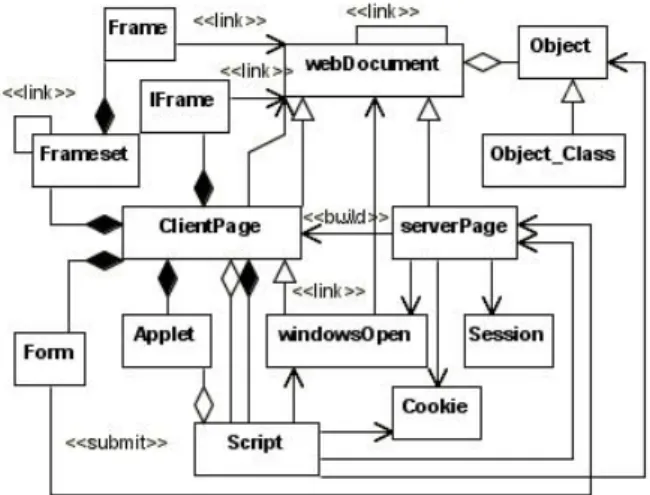
in a “Main” fictitious method. From a logical point of view, this (“Main”) method may be viewed as an implicit constructor of the same class. Figure 1 shows the class diagram meta-model used in the WAAT project. Every Web application model is an instance of this meta model. Instead, state diagrams are used to represent be-haviors and navigational structures of the elements described in the applications class diagram. A navigational structure may be com-posed of client and/or server pages, navigation links, frames sets, form inputs, scripting code flow control, and other static and dy-namic contents. The use of state diagrams let us model relevant assets, such as an active document (i.e., composed by HTML and client side scripting code). In particular, the state diagram of an active document can define the function calls flow of the script-ing code, and some relevant behaviors/navigation dynamic infor-mation (e.g., dynamic links, frames, and so on).In our model, a Web application is associated to a state diagram and Web docu-ments are associated to substates (subdiagrams). A static document is represented by a simple state, while an active document is rep-resented by a composed state that may be concurrent if the page contains client-side scripting code. Dynamic documents are mod-eled by simple or composed state. If the document does not contain some relevant navigation element, it is described with simple state, with composed state otherwise. E.g., a dynamic page that builds many client side HTML pages is modeled with a composed state with many substates, one for every HTML page generated. In gen-eral, the transitions are defined by links, function calls, and various HTML form inputs. An HTML frame set is modeled via composed concurrent state where every frame corresponds to a substate. See
Figure 1: Web Applications UML Meta-Model
[3] and [2] for more details and samples about the OO model used in the WAAT to describe applications. To the aims of this paper, we recall here that we introduce an approach to test Web software. Nevertheless, the OO-based model used to represent Web applica-tions is not really the focus of this paper because some existing OO-based modeling techniques may be useful with the testing ap-proach presented in this paper. Moreover, we use a set of reverse engineering techniques ([2]) to recovery UML models from exist-ing applications but OO-based models are often defined in a design phase of the development life-cycle and the proposed approach may be used too. The reverse-engineered model is based on static and dynamic analysis. The technique uses static methods derived from traditional source code analysis adapted to extract static and
dy-Figure 2: wTDG main rules
namic information from Web. Moreover a combined method based on static and dynamic analysis is used to define navigational struc-ture and application behavior. We have paid particular attention to the server side dynamic aspects of Web applications, we analyzed it with a dynamic method based on application execution and on mu-tational analysis applied to source code [2]. This dynamic analysis is performed with the generation of a set of source code mutants, used into navigation simulation. Then, procedure results are an-alyzed with static traditional source code techniques. The use of mutation lowers user interactions in the reverse engineering phase and let us defines a more detailed description.
To test an application we use its UML model composed of UML class and state diagrams to extract several kinds of information us-able to identify the units to test and/or to guide the test cases defini-tion and/or to calculate the code coverage reached with a set of test cases. In particular, using the class diagram we may build a graph of the system components dependencies. While, using a UML state diagram we may build an “extended function calls graph” (eFCG, “extended” for the presence of the fictitious methods) for the en-tire system (named class eFCG) and/or for every components (i.e., we may build a graph of the function calls for every system com-ponent). In this case, for every software component that it is rep-resented in the state diagram using a complex state (i.e., a state grouping a set of sub-states) we build a eFCG where every node is a sub-state and every edge is a state transition that exist among states. In the case of our OO model, transitions between states may be function calls (for both fictitious and not methods), link clicks, specific user gestures needed to evolve the software, and so on. Thus, a path in the eFCG represents a possible execution of the software under analysis.
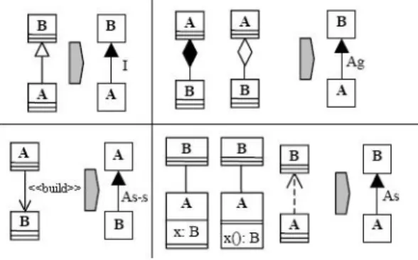
Several works studying the integration-orders problem use appli-cation models (i.e., the class diagrams) as a basis to build a graph representing dependencies among components. Then, this graph is used in order to search the best integration order. In case of Web software, we suggest to use the “Web Test Dependence Graph” (wTDG). [12] presents an extended version of the original TDG adapted for working with specific OO assets (polymorphic depen-dencies, as well as the nature of the dependence such as aggrega-tion, associaaggrega-tion, inheritance and so on). wTDG is a simplified ver-sion of this TDG at classes-level. wTDG is a directed graph whose vertices represent UML classes and directed edges represent de-pendencies among them. A wTDG may contain loops because a class may be directly or indirectly dependent from each other ones. In the TDG, an arrow from B to A means that “B is test dependent on A” thus, we need to test A before B. Figure 2 show four main rules of the wTDG construction used to map UML class diagrams in wTDG. Given two classes A and B:
1. If B extends A then A is test-dependent on B through an in-heritance dependence and in wTGD the edge that connects A to B is labeled “I”.
2. If A is a composition (or aggregation) of B, A is test-dependent on B through an aggregation dependence and the A to B edge is labeled “Ag”.
3. If A is associated or depends on B, A is test-dependent on B through an association dependence and the A to B edge is labeled “As”.
4. If A is associated to B through specific WAAT-model rela-tionships defined using the UML stereotype “<<build>>” (e.g., relationship existing between a server-side page and the built one or more client-side pages) thus, B is test-dependent on A through a specific association dependence and the A to B edge is labeled “As-s”.
Through this set of rules we may build a wTDG from a reverse engineered UML class diagram of Web applications.
3.
OTMW-BASED WEB TESTING
3.1
Rationale
The testing performed in the OTMW model is inspired by the category partition method (see [15] and [5]). This method is a spe-cific sub-type of the functional testing method known as “equiva-lence classes”-based testing (EC). The EC method, for every testing layer (unit, integration, system) defines subdivisions of the applica-tion input domain in equivalence classes which are used to derive test cases. The main ideas are that a failure found by one value in a class will be found by all values in the same class and that all components of a class are treated in analogous mode by the software (i.e., producing correlated results). The main goal of this type of test is to define test data that may reveal possible classes of errors/bugs. An equivalence class is represented using a set of (valid and/or not valid) input data and a set of software states for the output data produced through the class inputs. Thus, the cat-egory partition approach may be viewed as composed of the fol-lowing steps: software specification analysis to identify the func-tional unit to test (and for every one, identification of its parameters and the needed environments); classification of the identified units in categories; subdivision of the categories in choices; definition of constraints among the choices; definition and documentation of tests. In more details, the OTMW model may be used to test an ap-plication through a gray-box approach (i.e., a functional approach that considers some interesting structural information to perform the test) inspired by the category partition testing method and ap-plied in six main steps to perform unit, integration and system test-ing. These steps are the following:
• We need to build the OO model for the existing application under testing.
• When the application under test is described through UML class and state diagrams we use the class diagram to identify software units to test in isolation.
• Then, we perform the unit testing and thus, for the current unit under test, we use its state diagram to build its eFCG (graph of function calls and actions) and we use eFCG as a basis to define the test cases through the expected unit be-havior shown in this eFCG (and using the idea of the “equiv-alence class” to subdivide the input domain and to define the
set of representatives test cases). Then, we build the scaffold-ing (i.e., stubs, drivers, oracles) needed to test unit through the defined set of functional test cases. In particular, the scaf-folding may be expressed in terms of fragments of code (i.e., scripting code) written using a set of XUnit tools. Thus, we may execute every test case using these XUnit-based code. • Then we need to identify the integration order of system units
needed to test the software components interactions (i.e., the definition of the best user-adequate unit sequences). In this phase, we use the wTDG graph, built from UML class di-agram, to extract information about the components depen-dencies and we use a genetic-based algorithm that analyzes some coupling measurements among components in order to devise the best set of sequences usable to test the components integration.
• Then we test every cluster identified in the previous step (a cluster is a group of software units collaborating among them). In this case, we treat a cluster as a “big-unit” and we use the merge of eFCGs for units in the same cluster to de-fine the functional test cases and then to write scripting code using the XUnit tools. Thus, we may test clusters using these written classes of test.
• In the last step of OTMW we need to perform system test-ing. In particular, we use the UML models to build a graph considering only high level information in order to describe the application as a graph composed of nodes representing pages (considering client or server side and static or dynam-ically generated pages) and edges representing links existing among pages. Through this graph, we perform some ran-dom walks paths to traverse the graph and to simulate user navigations using a set of sequences of URLs randomly gen-erated based on the graph coverage (i.e., nodes/edges/ paths coverage).
The OTMW layered model lets us perform different kinds of test, for example, in the unit testing we test every component of the software architecture. A Web application may be written in sev-eral languages and may be composed of some different components collaborating among them. A component may be a client-side page (e.g., composed of HTML and Javascript code), a server page (e.g., composed of PHP 4/5 code), and Web object and/or other compo-nent (e.g., written in PHP, or ActiveX, or other server/client-side scripting code, XML files and database, and so on). In particular, for a complex page/object (such as written in PHP) we may test its functionalities, or its main execution paths stressing several se-quences of methods defined in the same page/object. On the other hand, through the integration testing we test the integration (i.e., collaborations) of the software components. Thus, we treat a clus-ter (i.e., group of software unit) as a unique unit with an inclus-terface composed of the sum of the units interfaces, this let us test more and more invoked sequences to stress methods of every unit in order to analyze every state of the evolution and/or execution of every unit. Finally, the system testing let us perform the conventional pages-based testing in order to focus the test in the navigational system and the structure of the application (i.e., sequences of pages). In the following sub-sections we analyze and describe every step with several details in order to guide the user (i.e., Web testers) to use our OTMW to test Web applications.
3.2
Unit Testing
The main steps of the OTMW unit test are: identification of units to test in isolation; test cases definition (using a testing table defined
through the analysis of the inputs and the eFCG for the current unit under test); identification of the needed drivers and stubs; and test script description using XUnit tools.
To test the elements composing the software we need to use the UML class diagram used to describe it. We use this diagram to identify the units that we may test in isolation. These kinds of units may be:
• static HTML pages (with or without scripting codes) • client side objects such as the scripting codes (e.g., fragments
of Javascript code)
• server side objects (e.g., objects written in PHP 4/5) • server pages written in PHP 4/5 and their set of dynamically
generated HTML client-side pages (we consider a server side page and its dynamically generated pages such as a unique unit)
• client-side scripting code (e.g., Javascript) generating a set of HTML pages (we consider as unique unit)
• Web objects and components (such as txt file, xml, database, and so on)
• other components not previously classified.
However, the analysis of the dependencies (and their types) de-scribed in the UML class diagram may be used to define compo-nents representing units that may be tested in isolation and to iden-tify they needed stubs. A Stub is a fictitious module simulating the part of software called from the object under test. In particular, dependencies such as: inheritances, compositions, <<build>> are traditionally considered as “not breakable” while other such as associations, aggregations, <<submit>>, and so on, may be breakable. This information and the different kinds of elements listed before may help us to identify units and stubs. For example, a PHP server page that uses a PHP object to build a set of three dynamically generated HTML pages may be viewed as composed of two units. The first is the PHP object used by the server page while the other is the server page with its three generated HTML pages. Moreover, this last unit uses the PHP object and thus, this unit needs a stub to execute it in the testing phase.
For every identified unit we build its testing table (inspired by the decision table defined in [5] for OO software and then refined in [9] for Web software). This table is used to define a set of test cases through our method inspired by the traditional category partition approach. For the definition of a testing table for a unit: we need to identify the input parameters of the unit (from our UML class diagram); and then we need to describe the eFCG (the graph that describes the unit executions in terms of function calls and actions performed) for the modules composing the unit under test. We use eFCGs to extract several paths (i.e., a path represents a possible software execution at level of function calls and actions sequence) through the traditional coverage criteria (such as: nodes, edges, n-cycles path, couples of def-use, and so on coverage) applied to the same graph. These paths are the basic information to define test cases. For example, the eFCG for a PHP object may be a function calls graph. Thus, traversing the graph through the coverage graph criteria, we may extract several paths where every path is composed of a sequence of methods (i.e., defined/used in/by PHP object) calls and it represents a possible execution of the PHP object. Then, we use these information as a basis to fill the testing table for the unit under test. Figure 1 shows the skeleton of a testing table composed
Input Output
Variables Actions State Expected [Expected State Before Output Output After
Testing Actions] Testing
... ...
Table 1: skeleton of Testing Table
of two sections: the first for the input data and the other for output (expected) data.
A table is composed of six sections as following:
• Variables: listing of the unit input. For example, for
client-side page the input fields of its HTML forms, for client-client-side scripting functions the HTML DOM-tags, for server pages the needed GET/POST variables, and so on.
• Actions: listing the actions (i.e., user gestures, function calls,
class instantiations, and so on) needed to perform the test-ing. In particular, it represents a sequence of actions needed to realize the unit execution extracted from the eFCG. For example: link clicks, button press, method calls, class in-stantiations, and so on.
• State Before Testing: containing the values assumed before
the test from specific application elements such as client-side pages, cookies, tags, the state of used Web objects, session variables, server objects, and so on.
• Expected Results: listing the expected output results when
the test is executed
• Expected Output Actions: describing the actions performed
by the pages/objects under test when the test case is executed (i.e., the functionality performed with the test case, e.g., login action, sending data, write files, and so on)
• State After Testing: describing the expected values assumed
after the test execution from specific application elements such as the same described in the “State Before Testing” sec-tion.
Notice that to fill the Actions section, the user (i.e., tester) needs to identify the steps (user actions, method calls, objects instantia-tion, etc.) useful to implement the execution path extracted from the eFCG of the unit under test. Thus, the user may define more than one sequence of steps usable to perform a single eFCG path. In our testing table, the combination of Input Variables and
Ac-tions is used to identify the equivalence classes (EC) and thus, it
is used to subdivide the input domain of the application unit (com-posed of input variables and states of the components under test) in classes usable to derive several test cases of the same classes (e.g., changing the input values). When the testing table is filled we may proceed writing the scripting to execute test cases through specific XUnit tools. For example, to test HTML-based pages we may use tools such as: HTTPunit or HTMLUnit5 but also HTML
Tidy6, HTML validators7; to test server side objects written in PHP 4/5 we may use tools such as PHPUnit or PHP Assertion [1]; to test objects based on Javascripts code we may use HTMLUnit or JSUnit8or Javascript Assertion Unit; to test components based on
5http://htmlunit.sourceforge.net 6http://www.w3.org/People/Raggett/tidy 7 http://validator.w3.org 8 http://www.edwardh.com/jsunit
more than one language (e.g., client side pages that send data to server side pages we may use combination of this tools). In par-ticular, every row of the table may represent a class of test cases and may be converted in a testing script using these XUnit tools. Then we may proceed with the test cases execution using the ad-hoc written script code and repeating its execution using several different input values.
Drivers and stubs modules are needed to test a given unit. A driver is a (guide) module simulating the pieces of program that invokes the object under test, and it is used to prepare the environ-ment needed to call the object under test in order to execute a test case (a driver may instance new objects, call methods, may define parameters and variables, and so on). Typical Web driver may be composed of fragments of code derived from pages or objects that interacts with the unit under test, filling HTML forms, generating events (e.g., to simulate user gestures), and so on. This type of code may include scripting fragments (client/server side), Web objects, DOM objects, and so on. Instead, a stub may be a client/server page/object that it is used by the unit under analysis in order to perform its task.
The main goals of this unit testing phase may be to test the loading, in some different context, of every elements composing the applications (e.g., pages, objects, page components such as forms, scripts, tables, server components, and so on); the struc-ture and navigational system of every component (e.g., elements compositions, self links, submitting operations, etc.); the evolution (in terms of states reached) of every complex components such as client/server side code (e.g., using JSUnit and PHPUnit we may test several different function calls sequences representing differ-ent software executions); and the construction of the dynamically generated pages (e.g., the HTML code generated by a server page).
3.3
Integration Testing
In the integration testing phase we test the interactions among software components (i.e., units identified in the previous testing step). In particular, we may test data or messages exchanged among units. For example, we may test the following cases:
• the data/messages exchanged between an HTML page and its Javascript code, such as function defined a Javascript frag-ment and called in an HTML tag with mouse events, or HTML tags filled with the returned value of a Javascript function. • data/messages exchanged among PHP objects, such as
func-tions or data variables in a PHP5 class but defined in another class.
• data/messages exchanged between an HTML page and a PHP page that elaborates these data to generate outputs (e.g., HTML form data submitted to PHP page, or PHP function called from HTML code)
• the use of several kinds of files (e.g., TXT, database, XML) to write, read, modify data from PHP or Javascript code • the use of scripting code or server-side applications by a PHP
object
Therefore, in a Web application we need to test some different types of interactions because every application may be written in more than one software language (e.g., HTML, Javascript, PHP, and so on). Thus, we need to test interactions such as among the following elements: HTML code and Javascript; Javascript and Javascript; Javascript and PHP; HTML and PHP; PHP and PHP;
Javascript, HTML and PHP; Javascript, HTML, PHP and other el-ements (TXT, database, XML); and so on. To verify the interac-tions among components we need to identify the sequence of units to test. Then, we need to treat every integration cluster (group of units in the sequence) as a single “unit” in order to fill its testing
table and to write its set of test cases.
Given a software system, to test its components and their re-lationships, the first problem is to decide the integration order, be-cause different orders may define some different complexity in terms of effort. For OO-modelled software it may be very difficult to choose the testing order because the system has specific assets (i.e., information hiding and abstraction, inheritance, and so on) and because the architectures may be very complex and several com-ponents may be strongly connected (i.e., cyclical dependencies). Thus, to define the best integration order we need to use a method studying the components dependencies and the scaffolding com-plexity. For example, we may consider a small system composed of four classes (A B C and D), and where “B uses C”, “C uses A”, and “D uses A”. In this case, some possible integration orders may be found defining a topological order9of the class-usage graph, for example A D C B or A C B D may be orders usable into integration testing. Instead, if this system contains another use relationship such as “A uses B” the system contains a dependencies loop (com-posed of the classes A B C), thus it is impossible to define a topo-logical order, but we may define a partial order such as A D C B (where A needs B as stub), or A C B D (where A needs B as stub). In literature, there are several works that use class diagrams rep-resenting OO systems (and defined during the analysis and design phase or extracted from code using reverse engineering techniques) as a basis to build graphs representing relationships among compo-nents then analyzed through deterministic or random approaches to find optimal integration orders. Most of the proposed strategies are focused on the analysis of this dependencies-graph derived in order to minimize the effort needed to test the application and (often) the effort is expressed in terms of stubs number (or complexity) needed to test using a specific integration order. In particular, the proposed solutions “break” some dependencies in cycles contained in graph to obtain an acyclic graph representing the dependencies of the en-tire system. This approach implies that the modules related to the broken relationships need to be stubbed in the integration testing. However, there are several deterministic and random approaches usable to define how to break cycles and devise orders, see [12] for a review of existing techniques and for some empirical com-parisons. These approaches may be grouped in four categories as following:
• finding of the strictly connected components (SCC) of the system (dependencies cycles); and to break some (one or more) randomly-selected dependencies in SCC
• finding the strictly connected components (SCC) of the sys-tem (dependencies cycles); to weigh every dependency in SCC counting the parameters passing through this depen-dency; and to break the dependency with the smaller weight • finding the strictly connected components (SCC) of the sys-tem (dependencies cycles); for every component in SCC count-ing the number of cycles it belongs to; and to break the com-ponent that is part of the highest cycles number
• finding the best orders using a genetic algorithm (i.e., a semi-random approach, see [6]) that uses the permutation
encod-9
A topological order is a node ordering for a direct graph such that each predecessor node of a given node is listed before the same node in the topological ordering
ing where every chromosome is a string of class labels and that defines a chromosome as an integration order (i.e., a sequence of system classes). Then to evolve the popula-tion using a set of genetic operators (selecpopula-tion, mutapopula-tion and crossover) and a fitness function based on the stubbing com-plexity (in terms of coupling measure between the current test order and its needed stubs).
When the units order has been defined we may start the test of every cluster composing this sequence. We test all clusters using the same methods and tools used in the unit testing, because we consider every cluster as a unique “unit” with an interface described as the sum of all units-interfaces composing the cluster. This let us define several invocation sequences to stress methods of all units in cluster, in order to verify the cluster in every state it may reach. Thus, for a cluster we need to identify its input variables, to define its needed stubs and drivers and to fill its testing table. We use eFCGs of units in cluster to define relationships existing among components, and then we extract several paths from these graphs through coverage criteria. Finally, we may filled testing table and we may use it to extract a set of test cases and to write the testing scripts using XUnit tools. Finally, we may execute them more than ones time using several different values for input variables.
3.4
System Testing
The system testing for a Web application may be essentially based on high level representation where the application is described through a graph composed of nodes corresponding to Web pages and edges corresponding to links. In our modeling approach, we may extract this graph from the UML class diagram. Then, the test consists in sequences of URLs requested to Web server with their inputs values (if needed). This test let us verify the naviga-tional system and the structure of Web application by traversing the graph. [4] shows the approach used in our WAAT project and implemented in TestUml tool. While, [14] describes another sim-ilar approach. We recall here that the main goal of this paper is to describe an approach to perform unit and integration testing of Web software. However, to perform system testing we traverse a given Web application simulating user (random) navigations and gestures. In particular, we use the application graph to extract several paths (sequences of URLs) selected through conventional coverage measures such as nodes or edges, n-cycles paths, def-use couples coverage, and so on. Then, these sequences (test cases) are completed with the needed input values and executed (more time) performing requests to the Web server. This testing method is semi-automatic due to the fact that the user (tester) must com-plete the inputs not randomly identified or extracted from log-files analysis.
4.
CASE STUDY
MiniLogin is a simple Web application we use to show how to apply the OTMW approach to existing software systems. This ap-plication is composed of some PHP5 and HTML files with Javascript, and its main functionality is to control the access to a reserved Web area through login and password. Through WebUml (see [3]), the tool that implements our reverse engineering techniques, we per-form static and dynamic analysis on this Web application in order to extract information needed to build MiniLogin UML model com-posed of UML class (Figure 3) and state diagrams. In the following sub-sections we show how to apply our Web testing approach to MiniLogin in case of unit and integration testing. Instead, for the system testing (we would like to recall here that it is not the main goal of this paper) see [4] for more information about techniques
Input Output
Variables Actions State Expected [Expected State
Before Output Output After
Testing Actions] Testing
Javascript 1
(1) ptagUsername,
1.load script in HTML def(formMain.user) true login and ptagPassword == 2.call controlData() def(formMain.psw) or password “is Number” or
3.read returned value def(ptagUsername) false verification “is String (with Number)”
def(ptagPassword) or “is String”
(2) ptagUsername ==
1.load script in HTML def(formMain.user) true login “is Number” or
2.call controlUsername() def(ptagPassword) or verification “is String (with Number)”
3.read returned value false or “is String”
control php (3)
$user, $psw 1.class instantion new String $user.$psw 2.call setCombine() equal to strings 3.read returned value $user.$psw concatenation (4)
$user, $psw 1.class instantion “one” or $user.$psw 2.call setCombine() “two” or” strings 3.call verify() “theree” or concatenation
using 2. result “error” and
4.read returned value verification
member php (5)
$user, $psw 1.class instantion def($count) to control the $count+1
2.call counter() $count session or
3.read returned value ... variable $count=0
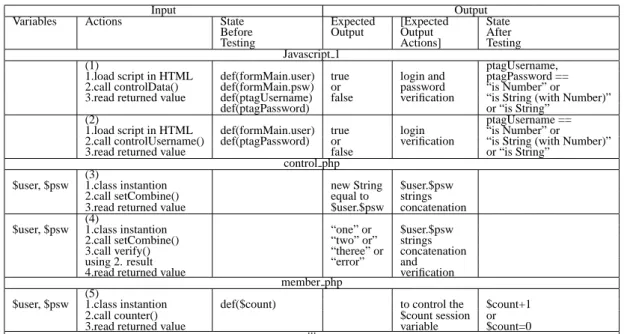
Table 2: MiniLogin samples of testing table
Figure 3: MiniLogin UML Class Diagram
used in the WAAT project to perform system testing as briefly in-troduced in the previous sections.
4.1
Unit Testing
We identify the unit to test considering different types of ele-ments composing the application UML class diagram (HTML static page, PHP page/object, HTML dynamically generated pages, etc.) and the types of the relationships existing among elements (associa-tions, aggrega(associa-tions, composi(associa-tions, etc.). For example, there are two Javascript objects (Javascript 1/2), one PHP page (member php), one PHP object (control php), several HTML pages, and so on. In the case of unit testing, for every unit we need to define stubs and drivers usable in the test phase. We identify these elements us-ing the dependencies described in the class diagram. For example, the PHP page named member php has (“use”) relationship with: PHP object named control php and with an HTML page (named access html). Instead, the PHP object control php has no relation-ship with other PHP elements but only one with a TXT file. Thus, control php may be tested as a unit stubbing the TXT file, while member php needs three stubs to be tested. Furthermore, to test a Javascript code usually we need to stub the fragment of the HTML
Figure 4: MiniLogin samples of eFCGs
page that interacts with this scripting code (and its DOM too). In our case, the object Javascript 1 needs to stub the index html page. For every unit we need to fill its testing table as described in the previous sections. In particular, we identify every method (con-sidering also the fictitious methods “Main”), we identify the input variables and the variables used by current unit but defined in other ones. For example, Javascript 1 contains a method named alertMsg that has four parameters as input. Furthermore, the same unit has a method named controlPsw that does not have input parameters but that uses two variables defined in another unit such as an HTML form field (i.e., formMain.password) and a HTML page tag (i.e., named ptagPassword in index html).
Then through the state diagram of every unit we build its eFCG (see Figure 4 for some Minilogin samples10). From this eFCG we
10
<head> <script src=’jsUnitCore.js’> </script> </head> ... <body> ...
<script name=’test’ language=JavaScript> function testcontrolData() { document.all.ptagUsername.innerText=’’ document.all.ptagPassword.innerText=’’ document.formMain.username.innerText=’prova’ document.formMain.password.innerText=’prova’ assertTrue(controlData()) assertEquals(document.all.ptagUsername.innerText, ’Username is String’); } function testcontrolUsername() { document.all.ptagUsername.innerText=’inizio’ document.formMain.username.innerText=’prova’ debug(document.all.ptagUsername.innerText); assertTrue(controlUsername()); debug(document.all.ptagUsername.innerText); assertEquals(document.all.ptagUsername.innerText, ’Username is String’); } </script> </body>
Figure 5: Javascritp 1 test cases: (1),(2)
extract some paths using the conventional coverage criteria (i.e., nodes or edges coverage) in order to select several possible execu-tions of the current unit (at funcion calls and acexecu-tions level). For example, considering the eFCGs in Figure 4 we may extract the following execution paths:
• Javascript 1: Main, controlData, ret; Main, controlData, con-trolUser, ret; Main, falseSubmit, alertMsg, end; (1)Main, controlData, alertMsg, ret; (2)Main, controlUser, ret; and so on
• control php: (3)Main, setCombine, ret; Main, verify, fileRead, ret; (4)Main, setCombine, verify; ret; Main, fileRead, fopen,ret, and so on
• member php: Main, get, get, writefile, control php.setCombine, sc, control php.verify, v; (5)Main, counter; Main, writeFile, counter; and so on
Through this set of information and using our knowledge about the MiniLogin application we may fill the testing table for every unit. Table 2 show fragments of testing tables for three units of the Minilogin application (i.e., Javascript 1, control php, and mem-ber php). Now, we may use the testing table with the XUnit tools to write test cases, every row of the table may represent a class of test cases that may be implemented in a testing script. For example, the rows (1) and (2) of Table 2 may be implemented with JSUnit tool as shown in Figure 5. Instead, the rows (3) and (4) may be implemented using PHPUnit2 as shown in Figure 6. Moreover, the row (5) may be also implemented through PHPUnit2 as shown in Figure 7. In this last case, to treat the member php page as a unit testable with XUnit tools we need to wrap the entire page code in a fictitious “Class member ...” and the main code of the same page on a fictitious method “function Main()...”. This lets us treat the PHP page as a conventional OO class. In the set of written testing cases, the only case that found a “bug” is for the control php object and it is named “testsetCombineVerify ErrorInTest()”. In particular, for information such as the label of the edges corresponding to actions to perform
<?php
require once(’PHPUnit2/Framework/TestCase.php’); require once(’control.php’);
class controlTest extends
PHPUnit2 Framework TestCase {
public function testsetCombine withStringValues(){ $control=new control(); $user="primo’; $psw=’secondo’; $expectedOutput=’primosecondo’; $output=$control->setCombine($user,$psw); $this->assertEquals($expectedOutput, $output); }
public function testsetCombineVerify error(){ $control=new control(); $user=’primo’; $psw=’secondo’; $expectedOutput=’error’; $output1=$control->setCombine($user,$psw); $output2=$control->verify($output1); $this->assertEquals($expectedOutput, $output2); }
public function testsetCombineVerify ErrorInTest(){ $control=new control(); $user=’user’; $psw=’one’; $expectedOutput=’one’; $output1=$control->setCombine($user,$psw); $output2=$control->verify($output1); $this->assertEquals($expectedOutput, $output2); }
public function testsetCombineVerify correct(){ $control=new control(); $user=’User1’; $psw=’One’; $expectedOutput=’one’; $output1=$control->setCombine($user,$psw); $output2=$control->verify($output1); $this->assertEquals($expectedOutput, $output2); } } ?>
Figure 6: control php test cases: (3),(4)
this test case we expect the string “one” as result but after the ex-ecution we obtain “error”, this is due to the fact that the fragments of PHP code written for this test case contains a mistake (i.e., not the application).
4.2
Integration Testing
To do integration test among software units, identified in the pre-vious step, we need to define an integration order among them (i.e., a sequence of units that helps us to define the order in which to test the units). Thus, from the MiniLogin class diagram we extract the wTDG and we use it to calculate some coupling measures among units. Then, we use this measures in wJenInt, that is our ad-hoc written tool implementing a genetic algorithm [6] usable to devise an optimal testing order through a fitness function based on cou-pling measure used to calculate the stubbing complexity (that is expressed in terms of coupling measures between the current order and its needed stubs). In the case of MiniLogin we have defined the following integration order: Javascript 1; psw txt; control php; img; member php; input; form; Javascript 2; index html; error-MoreTime html; error html; access html; clientPage php; client-Page 1; clientclient-Page 2; clientclient-Page 3. Through this order we need to cut only one dependency associating Javascript 1 and index html elements. Therefore, we need to test every cluster defined in this order and that contains units collaborating among them, for ex-ample, we test: psw txt -control php; (6)member php, control php (7)Javascript 1, input-form; Javascript 1, member php, input, form, index html; (8)member php, control php, clientPage php,
client-Input Output
Variables Actions State Expected [Expected State
Before Output Output After
Testing Actions] Testing
Cluster 1
(7.2) ptagUsername,
1.load index html def(formMain.user) ptagUsername== login and ptagUsername== 2.put user string def(formMain.psw) ’is String’ password “is String” and 3.onMouseOut activation def(index html.ptagUsername) +alert(Number Sedning) verification ‘ptagPassword== 4.call controlUsername() def(index html.ptagPassword) undef
5.click submit
6.onMouseClick activation 7.call controlData()
Cluster 2 (8)
$username 1.load index html def(formMain.user) access OK + username and $password 2.put real username def(ptagPassword) load access html + password
3.put real password 4.click submit 5.load access html 6.it contains gif and link
7.click link ...
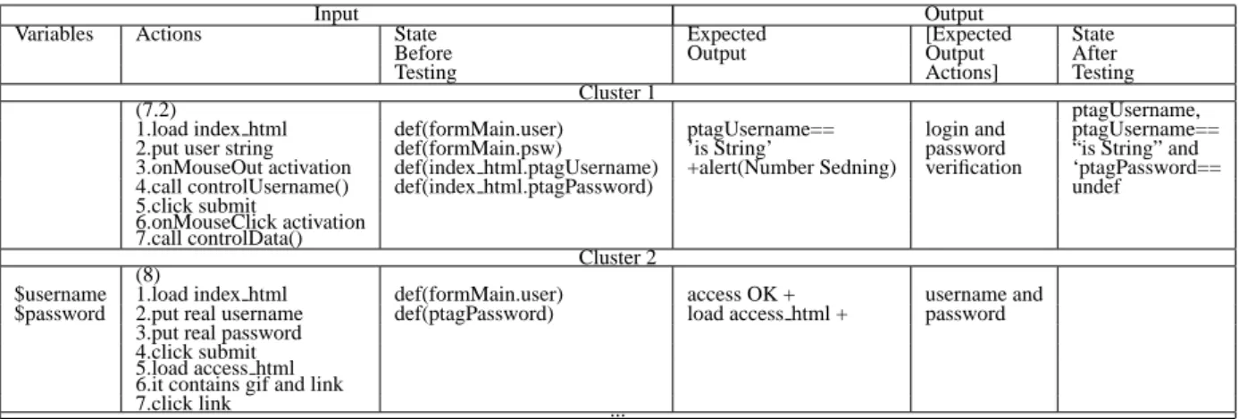
Table 3: MiniLogin samples of Integration testing table
import com.gargoylesoftware.htmlunit.*; import java.net.URL;
import com.gargoylesoftware.htmlunit.html.*; import junit.framework.TestCase;
import java.util.*;
public class SimpleHtmlUnitTest extends junit.framework.TestCase { public void testHomePage1() throws Exception {
WebClient webClient = new WebClient();
java.net.URL url = new java.net.URL(’http://localhost:8080/˜alex/logred2/index.html’);
HtmlPage page = (HtmlPage) webClient.getPage(url); assertEquals(’Home Page’, page.getTitleText()); HtmlForm form = page.getFormByName(’formMain’);
HtmlTextInput textField=(HtmlTextInput)form.getInputByName(’username’); textField.setValueAttribute(’prova’);
HtmlPage appWindow=(HtmlPage) page.executeJavaScriptIfPossible(
textField.getOnMouseOutAttribute(),’testCU’,false,textField).getNewPage(); assertEquals(’Home Page’, appWindow.getTitleText());
assertEquals(’Username is String’,
appWindow.getHtmlElementById(’ptagUsername’).getFirstChild().asText() ); HtmlSubmitInput button = (HtmlSubmitInput)form.getInputByName(’Submit’);
List collectedAlerts = new ArrayList();
webClient.setAlertHandler( new CollectingAlertHandler(collectedAlerts) ); HtmlPage newPage = (HtmlPage)button.click();
List expectedAlerts = Collections.singletonList(’Number sending’); [or ’Numbero sending’] assertEquals( expectedAlerts, collectedAlerts );
} }
Figure 8: cluste1 test case (7.2)
<?php
require once(’PHPUnit2/Framework/TestCase.php’); require once(’member.php’);
class memberTest extends
PHPUnit2 Framework_TestCase { public function testcounter 1(){
$mem=new member(); $mem->counter1();
$this->assertEquals(0, $ SESSION[’count’]); }
public function testcounter_2(){ $mem=new member(); for($contatore=1;$contatore<=10;$contatore++){ $mem->counter1();} $this->assertEquals(10, $_SESSION[’count’]); } } ?>
Figure 7: member php test case (5)
Page 1, access html; and so on.
For every cluster we use the eFCGs of its units identifying the in-vocation sequences of methods/variables used among units to col-laborate. For example, for (6) may be: (member php.Main &
con-trol php.Main), member php.wF, concon-trol php.setCombine, concon-trol php.verify. While, for (7) possible sequences may be: (7.1) (index html.Main
& Javacript 1.Main & input.Main & form.Main), formMain.user, input.onMouseOver, Javacript 1.controlUser; (7.2) (index html.Main & Javacript 1.Main & input.Main & form.Main), formMain.user, input.onMouseOut, Javacript 1.controlUser, formMain.submit, in-put.onMouseClick, Javacript 1.controlUser; and so on. While for (8) a possible sequence may be: (member php.Main & control php.Main), member.writeFile, control php.setCombine, control php.verify, client-Page.Main, clientPage.cp1, cp1.Main, cp1.Main, cp1.gif, cp1.link, index html.Main;
Then, we may fill the testing tables (see Table 3 for samples) for clusters and, using XUnit tools we may write the scripting code to test clusters. Tables 8 and 9 show the testing classes written in
import com.gargoylesoftware.htmlunit.*; import java.net.URL;
import com.gargoylesoftware.htmlunit.html.*; import junit.framework.TestCase;
import java.util.*;
public class SimpleHtmlUnitTest extends junit.framework.TestCase { public void testHomePage1() throws Exception {
WebClient webClient = new WebClient();
java.net.URL url = new java.net.URL(’http://localhost:8080/˜alex/logred2/index.html’);
HtmlPage page = (HtmlPage) webClient.getPage(url); assertEquals(’Home Page’, page.getTitleText()); HtmlForm form = page.getFormByName(’formMain’);
HtmlTextInput textField=(HtmlTextInput)form.getInputByName(’username’); textField.setValueAttribute(’User1’);
HtmlTextInput textField2=(HtmlTextInput)form.getInputByName(’password’); textField2.setValueAttribute(’One’);
HtmlPage appWindow1=(HtmlPage) page.executeJavaScriptIfPossible(textField.getOnMouseOutAttribute(), ’testCU’,false,textField).getNewPage();
assertEquals(’Home Page’, appWindow1.getTitleText()); assertEquals(’Username is String’,
appWindow1.getHtmlElementById(’ptagUsername’).getFirstChild().asText() );
HtmlPage appWindow2=(HtmlPage) page.executeJavaScriptIfPossible(textField2.getOnMouseOutAttribute(), ’testCP’,false,textField2).getNewPage();
assertEquals(’Home Page’, appWindow2.getTitleText()); assertEquals(’Password is String’,
appWindow2.getHtmlElementById(’ptagPassword’).getFirstChild().asText() ); HtmlSubmitInput button = (HtmlSubmitInput)form.getInputByName(’Submit’);
List collectedAlerts = new ArrayList();
webClient.setAlertHandler( new CollectingAlertHandler(collectedAlerts) ); HtmlPage newPage = (HtmlPage)button.click();
List expectedAlerts = Collections.singletonList(’<username>User1</username><password>One<password>’); assertEquals( expectedAlerts, collectedAlerts );
assertEquals(’ACCESS’, newPage.getTitleText()); HtmlElement root=newPage.getDocumentElement(); List imgs=root.getHtmlElementsByTagName(’img’); assertEquals(1,imgs.size());
assertNotNull(newPage.getAnchorByHref(’index.html’)); HtmlAnchor link = newPage.getAnchorByHref(’index.html’); HtmlPage page3 = (HtmlPage) link.click();
assertEquals(’Home Page’, page3.getTitleText()); }
}
Figure 9: cluste2 test case (8)
HTMLUnit and related to test cases (7.2) and (8).
When testing classes are written using the filled testing tables we may perform the test by repeating the test cases execution changing input values.
4.3
System Testing
We recall here that it is not the main goal of this paper, see [4] for details about the system testing performed in our WAAT project. Generally speaking, using TestUml tool from the class diagram we build an high level graph of the application under test where nodes are Minilogin Web pages and edges are links. Then we use cover-age criteria and random walks analysis to extract some paths that helps us to traverse the application graph and to simulate user nav-igations and gestures. In this case of system testing, a test case is a sequence of URLs (of the pages composing the defined se-quence) and its input values. For example, in case of Minilogin ap-plication the following sequences of URLs and inputs (expressed in the form<page to load, [list of parameters values]>) may be a set of test cases: (index.html), (member.php); (index.html), (mem-ber.php, “username”, “password”), (access.html); (mem(mem-ber.php, “user1”, “psw1”), (errorTime.html); (member.php, “user2”, “psw2”), (er-ror.html), (index.html); and so on.
5.
CONCLUSIONS
In this paper we have presented our OTMW framework usable
to test Web applications through an OO approach. In OTMW we use an OO model to describe applications from a logical point of view and then we identify software units testable in isolation (such as client and/or server Web pages, scripting code, Web objects, and so on) and, for every one, we perform a category-partition derived technique to test it at function call level. Then, we use an existing technique to derive an integration order (i.e., sequence of units) and we use it to select clusters (i.e., group of units of the order) to test using the same functional-derived approach. Finally, we perform a system testing using traditional Web testing in terms of sequences of URLs. Through this OTMW framework we treat (i.e., design and test) Web software as traditional OO software in order to test several aspects such as navigational system, functionalities, struc-ture and, in order to test every component in every state, in differ-ent execution contexts, in isolation and in collaboration with other components exchanging data or messages. Moreover, OTMW uses tools developed in our laboratory for the WAAT project (such as WebUml, TestUml, wJenInt) but to execute the test cases it uses traditional XUnit testing for Web applications.
6.
REFERENCES
[1] Php assertion.
http://jsassertunit.sourceforge.net/docs/phpassertunit.html.
[2] C. Bellettini, A. Marchetto, and A. Trentini. Dynamic Extraction of Web Applications Models via Mutation
Analysis. Journal of Information -An International
Interdisciplinary Journal- Special Issue on Software Engineering, 2005.
[3] C. Bellettini, A. Marchetto, and A. Trentini. WebUml: Reverse Engineering of Web Applications. 19th ACM
Symposium on Applied Computing (SAC 2004), Nicosia,
Cyprus. March 2004.
[4] C. Bellettini, A. Marchetto, and A. Trentini. TestUml: User-Metrics Driver Web Applications Testing. 20th ACM
Symposium on Applied Computing (SAC 2005), Santa Fe,
New Mexico, USA. March 2005.
[5] R. Binder. Testing Object-Oriented Systems. Addison-Wesley, 1999.
[6] L. Briand, J. Feng, and L. Y. Using genetic algorithms and coupling measures to devise optimal integration test orders.
14th international conference on Software engineering and knowledge engineering, Italy. 2002.
[7] S. Ceri, P. Fraternali, and A. Bongio. Web Modeling Language (WebML): a modeling language for designing Web sites. Ninth International World Wide Web Conference
(WWW9), Amsterdam, Netherlands. May, 2000.
[8] J. Conallen. Building Web Applications with UML. Addison-Wesley, 2000.
[9] G. A. Di Lucca, A. Fasolino, F. Faralli, and U. De Carlini. Testing Web Applications. International Conference on
Software Maintenance (ICSM’02), Montreal, Canada.
October 2002.
[10] C. Kallepalli and J. Tian. Measuring and Modeling Usage and Reliability for Statistical Web Testing. Ieee Transactions
on Software Engineering, November 2001.
[11] D. C. Kung, C. H. Liu, and P. Hsia. An Object Oriented Web Test Model for Testing Web Applications. 24th International
Computer Software and Applications Conference (COMPSAC 2000), Taipei, Taiwan. October 2000.
[12] V. Le Hanh, K. Akif, Y. Le Traon, and J. J´ez´equel. Selecting an Efficient OO Integration Testing Strategy: An
Experimental Comparison of Actual Strategies. 15th
European Conference on Object-Oriented Programming (ECOOP2001), 2001.
[13] F. Ricca and P. Tonella. Building a Tool for the Analysis and Testing of Web Applications: Problems and Solutions. Tools
and Algorithms for the Construction and Analysis of Systems (TACAS’200), Genova, Italy. April 2001.
[14] F. Ricca and P. Tonella. Analysis and Testing of Web Applications. 23th International Conference on Software
Engineering (ICSE’2001), Toronto, Canada. May 2001.
[15] M. Young and M. Pezz`e. Software Testing and Analysis: Process, Principles and Techniques. John Wiley and Sons