Volume 2008, Article ID 287197,7pages doi:10.1155/2008/287197
Research Article
Are the Wavelet Transforms the Best Filter Banks for
Image Compression?
Ilangko Balasingham1, 2and Tor A. Ramstad2
1Interventional Center, Rikshospitalet University Hospital, Oslo 0027, Norway
2Department of Electronics and Telecommunications, Norwegian University of Science and Technology (NTNU), Trondheim 7491, Norway
Correspondence should be addressed to Ilangko Balasingham,[email protected]
Received 22 October 2007; Accepted 6 January 2008
Recommended by James Fowler
Maximum regular wavelet filter banks have received much attention in the literature, and it is a general conception that they enjoy some type of optimality for image coding purposes. To investigate this claim, this article focuses on one particularbiorthogonal
wavelet filter bank, namely, the 2-channel 9/7. As a comparison, we generate all possible 9/7 filter banks with perfect reconstruc-tion and linear phase while having a different number of zeros atz= −1 for both analysis and synthesis lowpass filters. The best performance is obtained when the filter bank has 2/2 zeros atz= −1 for the analysis and synthesis lowpass filters, respectively. The competing wavelet 9/7 filter bank, which has 4/4 zeros atz= −1, is thus judged inferior both in terms of objective error measure-ments and informal visual inspections. It is further shown that the 9/7 wavelet filter bank can be obtained using gain-optimized 9/7 filter bank.
Copyright © 2008 I. Balasingham and T. A. Ramstad. This is an open access article distributed under the Creative Commons Attribution License, which permits unrestricted use, distribution, and reproduction in any medium, provided the original work is properly cited.
1. INTRODUCTION
The transform is one of three major building blocks in wave-form image compression systems, where quantization and coding are the two other blocks. It has been stated in the literature by many researchers that choice of decomposition
transformation is a critical issue, which affects the
perfor-mances of the image compression system.
There are some differences in designing filters in filter
banks compared with wavelet transforms. Wavelet filters are designed using associated continuous scaling functions and iterations. The filters in filter banks do not have to be asso-ciated with a single filter or basis function. They can be de-signed and optimized in many ways. However, the most com-monly used image compression systems employ filters with perfect reconstruction (PR), finite impulse response (FIR), and linear phase, and they are nonunitary (biorthogonal). It should be noted that when more constraints are imposed on a filter bank, fewer variables will be available for optimiza-tion.
Appropriate filter design criteria adapted to our visual perception used for image compression still remain an
un-solved issue. For wavelet filters it has been proposed to have biorthogonal, maximum regularity, minimum shift-variance, minimum impulse response peak to sidelobe peak
ratio, step response ratio, and so on [1,2]. The filter bank
designers on the other hand have proposed relaxation of per-fect reconstruction, shorter synthesis highpass/bandpass fil-ters, maximum coding gain, “bell-shape” synthesis lowpass filter, half-whitening property in analysis lowpass filter, and
so on [3–9].
other subjectively important measures while using moderate length filters.
One of the objectives of this paper is to study 2-channel 9/7 biorthogonal filter banks. We derive all possible filter banks that have PR and linear phase properties and show that biorthogonal wavelet filters can be obtained by using appropriate number of zeros on the unit circle, where re-maining degrees of freedom are used to maximize for sub-band coding gain. Furthermore, we show that optimal fil-ters can be obtained by relaxing maximum regularity con-straint used in the wavelet theory, where the additional de-grees of freedom can be used for subband coding gain. Both the wavelet and gain optimized filters are compared in a JPEG 2000 compliant image compression scheme, where objec-tive error measurements and subjecobjec-tive assessments will be given.
2. DECOMPOSITION TRANSFORMS
The transform is meant to transfer the signals from one do-main into another, where signal dependencies (correlations) are removed. The quantization renders a digital representa-tion of the signal parameters while allowing a certain signal
degradation, while coding is used for efficient bit
representa-tion.
The design criteria used in the wavelet transforms and
filter banks differ, and the rest of this section is devoted to
this topic.
2.1. Filter banks
Two-channel uniform filter banks are considered in the
fol-lowing. We enforce PR in the following way, whereHLP(z)
is a lowpass (LP) filter, andHHP(z) is a highpass (HP) filter.
The filters can be described in polyphase form as
H(z)=
HLP(z)
HHP(z)
=
P00(z2) P01(z2)
P10(z2) P11(z2)
1 z−1
=P(z2)d(z),
(1)
where the polyphase matrix,P(z) and the delay vector,d(z),
are easily identified in this equation [10].
Denoting the polyphase reconstruction filter matrix by
Q(z), a sufficient condition for PR can be expressed as [11]
Q(z)=z−kP−1(z), (2)
wherek is an integer representing a necessary delay. Given
FIR analysis filters, FIR synthesis filters are obtained by
set-ting all coefficients except one to zero in the polynomial
rep-resenting the determinant ofP(z). Denoting the synthesis
fil-ters byGLP(z) andGHP(z), respectively, the above condition
implies thatGLP(z) = HHP(−z) andGHP(z) = −HLP(−z).
Observe the close connection between the analysis and syn-thesis filters which simply represents an LP to HP transform
through frequency shifts byπ.
Table1: Possible combinations that give zeros atz= −1. Number
of zeros Solution Gain (dB)
Number
of zeros Solution Gain (dB)
0/0 yes 6.505 4/4 yes 5.916
0/2 yes 6.498 4/6 no —
0/4 yes 6.319 6/0 yes 1.015
0/6 yes 3.371 6/2 yes 0.910
2/0 yes 6.505 6/4 no —
2/2 yes 6.496 6/6 no —
2/4 yes 6.266 8/0 yes −30.123
2/6 yes 3.070 8/2 no —
4/0 yes 6.505 8/4 no —
4/2 yes 6.305 8/6 no —
The above constraints are the most general to construct PR system having FIR filters. If linear phase filters are desired, the system becomes nonunitary (biorthogonal).
2.2. Regularity constraint
In wavelet theory, regularity has been defined as a smooth-ness measure of a wavelet transform. It has been shown that a wavelet to have regularity, the analysis and synthesis
low-pass filtersHLP(z) andGLP(z) should have a sufficient
num-ber of zeros atz= −1. Consequently, it can be stated that if
HLP(z) hasNzeros atz = −1, the corresponding synthesis
highpass filter,GHP(z) will haveNvanishing moments [12].
A study on maximum regularity in orthogonal systems can
be found in [13]. However, our focus in this paper is only for
biorthogonal,linear phasesystems.
Let us investigate the importance of zeros atz = −1 for
the analysis and synthesis lowpass filters. A hypothesis is that in order to alleviate perceptually annoying noise, the DC gain of the odd and even polyphase lowpass synthesis filter com-ponents should be equal. This will prevent the generation of a periodic output from the synthesis filter whenever the in-put is constant and will also reduce cyclostationary noise in general. This requirement will force at least one zero to be
exactly atz= −1 for odd length lowpass filters.
Consider the synthesis lowpass filter written in polyphase form:
GLP(z)=Q00(z2)z−1+Q01(z2). (3)
A zero atz= −1 is equivalent to
GLP(−1)= −Q00(1) +Q01(1)=0, (4)
which implies thatQ00(1)=Q01(1). This is exactly the
equal-ity between the DC amplification of the two polyphase com-ponents.
Now for odd length, lowpass,linear phaseFIR filters with
one zero atz= −1, an additional zero would also have to be
placed at the same position. Or in general, zeros atz = −1
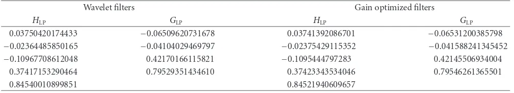
Table2: Wavelet and gain optimized filters for 4/4 zerosz= −1.
Wavelet filters Gain optimized filters
HLP GLP HLP GLP
0.03750420174433 −0.06509620731678 0.03741392086701 −0.06531200385798
−0.02364485850165 −0.04104029469797 −0.02375429115352 −0.041588241345452
−0.10967708612048 0.42170166115821 −0.1095444797283 0.42145506934004
0.37417153290464 0.79529351434610 0.37423343534046 0.79546261365501
0.84540010899851 0.84521940609657
It should be noted that for even length filters there will
always be at least one zero atz= −1. The DC gain condition
can also be seen to be satisfied by observing that the coef-ficients of the two polyphase filters are reversed versions of each other.
Another feature which seems important is that as images have strong low-frequency components, the analysis
high-pass filter should have at least one zero at z = 1. But this
is equivalent to the previous requirement due to the derived relationship between analysis and synthesis filters.
The question is now, do we get even better performance by increasing the multiplicity of these zeros?
To scrutinize this problem, we investigate a 9/7 filter
bank.
2.3. 9/7 Perfect reconstruction linear phase transforms
The analysis 9/7 filter pairs can be written as
HLP(z)=1 +a0z−1+a1z−2+a2z−3+a3z−4+a2z−5
+a1z−6+a0z−7+z−8,
HHP(z)=1 +b0z−1+b1z−2+b2z−3+b1z−4+b0z−5+z−6.
(5)
We assume using optimum bit allocation to quantize the
analysis samples as described in [14]. Then we can write
the subband coding gain relative to pulse code modulation (PCM) as
GSBC=
σ2
rPCM σ2
ropt
=1 1
i=0(hTiRxxhigTigi)1
/2. (6)
Here Rxx is the autocorrelation matrix of the input signal
x(n) where the entries areRxx(i,j)=E[x(i)x(j)], andhiand
gi are theith channel’s analysis and synthesis filter vectors,
respectively. Furthermore,σ2
r = 1
i=0(1/2)gTigiσqi2, whereσqi2
denotes quantization noise in theith channel.
There are 20 possible combinations to have zeros at
z= −1, as given inTable 1. (Number of zeros means:
num-ber of zeros atz= −1 for lowpass: analysis/synthesis filters.)
However, as shown in the table, not all possible combinations
of zeros atz= −1 will satisfy the PR and linear phase
prop-erties. This means we have only 14 combinations. In the case
of 4/4 zeros atz= −1, the 9/7 wavelet [12] and gained
opti-mized filter banks coincide, and are, in fact, the only
possibil-ity. The filter coefficients are given inTable 2. The rest of the
filter coefficients can be found by using the symmetric
prop-erty. Note that the synthesis filters have unit gain, that is, their
l2norm is equal to 1, which implies thatσr2=(1/2)[σq21+σ
2
q2].
3. OPTIMIZATION STRATEGIES: SUBBAND CODING GAIN
After linear phase and PR being imposed on a filter bank, the remaining degrees of freedom can be used for gain
optimiza-tion (see (6)), or more importantly, to achieve subjectively
good performance. It is obvious that the more degrees of freedom that can be exploited towards a given optimization criterion, the better. The correspondence between subjective criteria and simple mathematical criteria, as used presently, is rather poor. Typically, filter banks are designed to mini-mize the mean square error (MSE) after signal decompres-sion for a given source statistics and quantization scheme. Furthermore, encapsulating subjective performance criteria into a set of mathematical equations which can be incorpo-rated into an overall optimization criterion is warranted.
We choose the cost function to be defined in terms of
coding gain, which is given in (6). The coding gain can be
seen as a measure to assess the data compression ratio [15].
Katto and Yasuda [4] generalized the measure to be used in
biorthogonal, nonuniform (e.g., wavelet tree) filter banks. In the literature, it has been argued that most natural images can be approximated as an autoregressive (AR)
pro-cess, where the nearest sample autocorrelation coefficient
ρ=0.95. We will also use this model, implying that
Rxx=
1 ρ
ρ 1
(7)
will be used in (6). We used the “Optimization Toolbox” in
Matlab to optimize the cost function.
Table 1lists the coding gain optimization results for all possible configurations, of these the following have poor
coding gain (increasing gain order): 8/0, 6/2, 6/0, 2/6, and
0/6. There remain 7 possible zero combinations with gains in
the range 5.92 dB to 6.51 dB, where the 4/4 case (the wavelet
case) is inferior to the others. To make a comparison with the
wavelet transform, we rule out the 0/0, 2/0, and 4/0 cases, as
these lack the necessary regularity constraint. The 0/2 and
2/2 choices seem to be the best among the remaining
con-figurations. In peak-signal-to-noise ratio (PSNR)
compar-isons, the 2/2 case performed slightly better than 0/2 case
[16]. Therefore, we choose the 2/2 configuration.
Figure 1 shows the frequency responses of the
gain-optimized filter bank with 2/2 zeros at z = −1 and
the wavelet filter bank. The passband of the analysis opti-mized lowpass filter is slightly elevated, which is referred
−200
−150
−100
−50
0
0 0.1 0.2 0.3 0.4 0.5
A
m
plitude
Frequency
Figure1: Frequncy response of the analysis filters. Gain optimized 2/2 zeros atz= −1 (dashed) and wavelet 4/4 zeros atz= −1 (dot-ted).
approximation to the half-whitening property of the signal spectrum can be obtained with short length FIR filters.
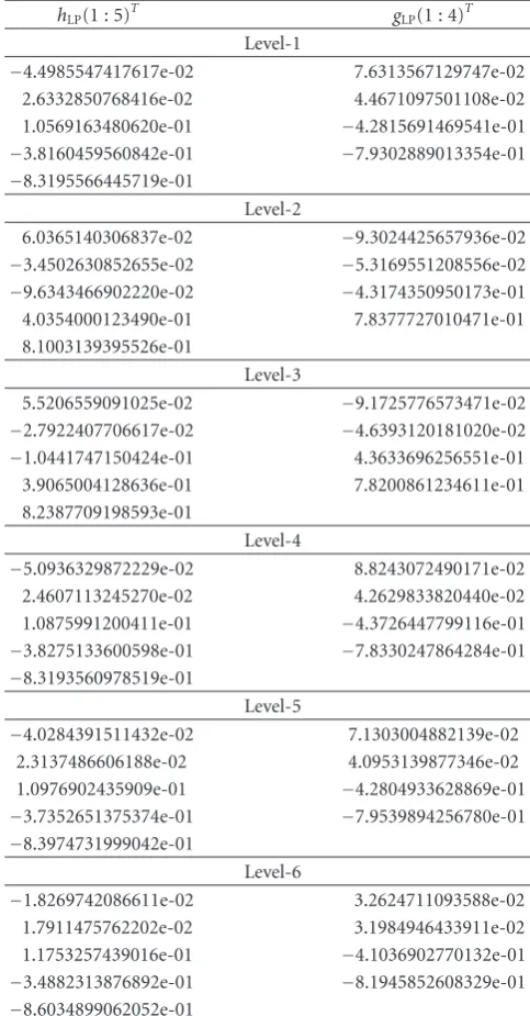
Table 3lists the gain optimized 2/2 case of the 9/7 filter
coefficients for 6 levels. Only the first 5 and 4 filter coefficients
of the analysis lowpass (hLP) and synthesis lowpass (gLP) are
listed, respectively. By using the symmetric and modulation
properties, highpass filter coefficients can be found. The filter
coefficients have different values in each level indicating that
the power spectrum in each level is different.
In the case of 4/4 zeros atz = −1, the wavelet 9/7
fil-ter bank [12] and gain optimized 9/7 filter bank have almost
identical filter coefficients as given inTable 2. Their zero
lo-cation diagrams are shown inFigure 2, whereas the zero
lo-cation diagrams for 2/2 case of the 9/7 filter bank are shown
inFigure 3.
4. RESULTS
Gray scale test images such asBike,Cafe,Target, andWoman
were chosen from the JPEG 2000 test set (JPEG 2000 com-pression test image CDROM ISO/IEC JTC 1/SC 29/WG1) where a JPEG 2000 complaint image coder was employed in
our experiment [17]. The bitrates used were 0.0625, 0.125,
0.25, and 0.5 bits/pixel (bpp). Furthermore, we have chosen to use the same objective error criteria used in the evalu-ation of the candidate image compression systems submit-ted to the JPEG 2000 comittee in 1997 in order to compare the competing filter banks, where only the
peak-signal-to-noise ratio (PSNR) is presented inTable 4. The gain
opti-mized filter bank performs better than the wavelet filter bank
for imageTarget. For all other images the wavelet and gain
optimized filter banks perform equally well. Comprehensive
coding results for a number of filter banks and different
fre-quency partitions can be found in [18,19]. So the question
now is whether the decoded images of both filter banks look the same.
During the evaluation of the JPEG 2000 candidates, an extensive subjective evaluation was performed. Both
objec-Table3: The gain optimized 9/7 filter bank (the 2/2 zeros atz= −1 case) analysis and synthesis lowpass filter coefficients.
hLP(1 : 5)T gLP(1 : 4)T
Level-1
−4.4985547417617e-02 7.6313567129747e-02
2.6332850768416e-02 4.4671097501108e-02
1.0569163480620e-01 −4.2815691469541e-01
−3.8160459560842e-01 −7.9302889013354e-01
−8.3195566445719e-01
Level-2
6.0365140306837e-02 −9.3024425657936e-02
−3.4502630852655e-02 −5.3169551208556e-02
−9.6343466902220e-02 −4.3174350950173e-01
4.0354000123490e-01 7.8377727010471e-01
8.1003139395526e-01
Level-3
5.5206559091025e-02 −9.1725776573471e-02
−2.7922407706617e-02 −4.6393120181020e-02
−1.0441747150424e-01 4.3633696256551e-01
3.9065004128636e-01 7.8200861234611e-01
8.2387709198593e-01
Level-4
−5.0936329872229e-02 8.8243072490171e-02
2.4607113245270e-02 4.2629833820440e-02
1.0875991200411e-01 −4.3726447799116e-01
−3.8275133600598e-01 −7.8330247864284e-01
−8.3193560978519e-01
Level-5
−4.0284391511432e-02 7.1303004882139e-02
2.3137486606188e-02 4.0953139877346e-02
1.0976902435909e-01 −4.2804933628869e-01
−3.7352651375374e-01 −7.9539894256780e-01
−8.3974731999042e-01
Level-6
−1.8269742086611e-02 3.2624711093588e-02
1.7911475762202e-02 3.1984946433911e-02
1.1753257439016e-01 −4.1036902770132e-01
−3.4882313876892e-01 −8.1945852608329e-01
−8.6034899062052e-01
tive and subjective evaluations were used to select the system for further development. We do not have resources to per-form a comprehensive subjective test. Let us rather inspect some images for annoying artifacts. If we compare the gain
optimized 9/7 filter bank (2/2 zeros atz = −1) and the 9/7
wavelet filter bank (4/4 zeros atz= −1), theringingartifact
becomes severe in the 4/4 case. To explain this, we examine
the synthesis lowpass filter’s unit sample response. For sim-plicity, the unit sample response of a 3-level decomposition
is shown inFigure 4. The unit sample responses of both 2/2
and 4/4 cases are obtained by convolving the unit sample
re-sponses ofeach level. For comparison purposes both filters
Table4: PSNR results: 9/7 wavelet and gain optimized filter banks.
Image Filter bank Wavelet
0.0625 0.125 0.25 0.5 Avg. 0.0625 0.125 0.25 0.50 Avg.
Bike 22.91 25.51 28.68 32.69 27.45 22.91 25.51 28.68 32.71 27.45
Cafe 19.00 20.63 23.05 26.53 22.30 19.02 20.66 23.08 26.58 22.34
Target 17.31 20.39 24.42 31.10 23.31 17.13 20.06 24.18 31.01 23.10
Woman 25.45 27.21 29.70 33.18 28.89 25.38 27.19 29.67 33.15 28.85
−2
−1.5
−1
−0.5
0 0.5 1 1.5 2
4
-1 0 1 2
Im
ag
inar
y
par
t
Real part (a)
−1.5
−1
−0.5
0 0.5 1 1.5
4
-1 0 1 2 3
Im
ag
inar
y
par
t
Real part (b)
Figure2: 4/4 zeros atz= −1 of the gain optimized and also wavelet 9/7 filter bank. (a) Analysis and (b) synthesis lowpass filters.
the magnitude of the side-lobes (negative unit sample values)
of the 4/4 case is much larger than in the 2/2 case, and this
leads to severeringingat low-bit rates. Furthermore, severe
checker boardandwaveformtypes of artifacts were observed
for the cases of 0/0, 2/0, and 4/0 zeros atz = −1 [20]. The
gain optimized 2/2 zeros atz = −1 had less ringing around
sharp edges than the wavelet filter bank (see image target
inFigure 5). Smooth regions and textures are better recon-structed by the gain optimized filter bank than the wavelet
filter bank (see imagecafeinFigure 6).
So far we have seen that the gain optimized and wavelet filter banks had similar objective measurements whereas
there are some differences in their visual appearances. Let us
see whether we can interpret our finding by inspecting the
power spectra of the images. The calculatedρin AR(1) model
for the images,Bike,Cafe,Target, andWoman, are 0.97, 0.92,
0.76, and 0.97, respectively. Furthermore,Womanand
Tar-get have the larger power spectral variations. The larger the
power spectral variations are, the higher the spectral
flat-ness measure becomes [15]. The spectral flatness measure is
used in the bit allocation scheme. This may be a reason that WomanandTargethave slightly better PSNR measurements
as given inTable 4.
TheBikeandWomanimages are best matched to the sta-tistical model used in the optimization. For other images there is a discrepancy between the selected model and the
calculated power spectrum of the image. Gain optimization based on the real power spectrum of the image may increase the performances of the filter bank. In this case, the
opti-mized synthesis filter coefficients have to be sent as a side
in-formation to the decoder. It may be also interesting to study further whether subjective error criteria can be formulated as a cost function along with the subband coding gain given in
(6) to obtain optimal filters.
5. CONCLUSIONS
All possible combinations of having zeros atz= −1 for
anal-ysis and synthesis lowpass filters for linear phase, perfect
re-construction, finite impulse response 9/7 filter bank were
de-rived. The popular 9/7 wavelet filter bank, which has 4/4
ze-ros atz = −1, is a special case and can be derived from the
gain optimized 9/7 filter bank. It was further shown that the
9/7 filter bank, which had 2/2 zeros atz = −1, had higher
theoretical coding gain, less ringing artifact, and slightly
bet-ter objective measurements than 9/7 wavelet filter bank. The
maximum regularity constraint in wavelets can be relaxed and therefore other optimizing criteria may be considered.
Based on our experiments the following low-complexity filter bank model can be suggested: a moderate number of levels, but high enough to get a fairly flat passband in the
−2
−1.5
−1
−0.5
0 0.5 1 1.5 2
2
-1 0 1 2
Im
ag
inar
y
par
t
Real part (a)
−1.5
−1
−0.5
0 0.5 1 1.5
2
-1 0 1 2 3
Im
ag
inar
y
par
t
Real part (b)
Figure3: 2/2 zeros atz= −1 of the gain optimized 9/7 filter bank. (a) Analysis and (b) synthesis lowpass filters.
−0.1
0 0.1 0.2 0.3 0.4
0 10 20 30 40
(a)
−0.1
0 0.1 0.2 0.3 0.4
0 10 20 30 40
(b)
Figure4: The 9/7 product unit sample response of the synthesis lowpass filter (43 taps). (a) Gain optimized and (b) wavelet [12].
(a) (b)
(a) (b)
Figure6: Lossy reconstruction of theCafeimage at bit rate of 0.125 bpp. Depicted region (420 : 820, 100 : 400). Result obtained during (a) gain optimized 2/2 zerosz= −1 filter bank and (b) 4/4 wavelet transform [12].
coefficients for each image. In practice, develop a small
code-book of typical filter banks from which close to optimal fil-ters can be selected for each image. Transmit the codebook index as side information. Based on this and the bit rate, the appropriate inverse filter including Wiener filters can be de-rived in the receiver. This may eliminate the observed mis-match between calculated power spectra of the images and AR(1) model.
REFERENCES
[1] J. D. Villasenor, B. Belzer, and J. Liao, “Wavelet filter evalua-tion for image compression,”IEEE Transactions on Image Pro-cessing, vol. 4, no. 8, pp. 1053–1060, 1995.
[2] O. Rioul, “Simple regularity criteria for subdivision schemes,”
SIAM Journal on Mathematical Analysis, vol. 23, no. 6, pp. 1544–1576, 1992.
[3] T. Kronander,Some aspects of perception based image coding, Ph.D. dissertation, Link¨oping University, Link¨oping, Sweden, 1989.
[4] J. Katto and Y. Yasuda, “Performance evaluation of subband coding and optimization of its filter coefficients,” inVisual Communications and Image Processing, vol. 1605 of Proceed-ings of SPIE, pp. 95–106, Boston, Mass, USA, November 1991. [5] E. A. B. da Silva and M. Ghanbari, “On the coding gain of wavlet transforms,” inProceedings of IEEE International Sym-posium on Circuits and Systems (ISCAS ’94), vol. 3, pp. 193– 196, London, UK, May-June 1994.
[6] S. O. Aase and T. A. Ramstad, “On the optimality of nonuni-tary filter banks in subband coders,”IEEE Transactions on Im-age Processing, vol. 4, no. 12, pp. 1585–1591, 1995.
[7] T. A. Ramstad, S. O. Aase, and J. H. Husøy,Subband Compres-sion of Images: Principles and Examples, Elsevier Science B.V., (North-Holland), Amsterdam, The Netherlands, 1995. [8] D. Akopian, M. Helsingius, and J. Astola, “Multibase/wavelet
transform coding of still images without blocking artifacts,” in
Proceedings of the 32nd Asilomar Conference on Signals, Systems and Computers, vol. 1, pp. 154–158, Pacific Grove, Calif, USA, November 1998.
[9] N. Patuck and D. McLernon, “Wavelet filter selection by clus-tering of image measures,” inProceedings of the 4th EURASIP Conference focused on Video/Image Processing and Multimedia
Communications (EC-VIP-MC ’03), vol. 1, pp. 375–380, Za-greb, Croatia, July 2003.
[10] M. Bellanger, G. Bonnerot, and M. Coudreuse, “Digital filter-ing by polyphase network: application to sample rate alter-ation and filter banks,”IEEE Transactions on Acoustics, Speech, and Signal Processing, vol. 24, no. 2, pp. 109–114, 1976. [11] P. P. Vaidyanathan, Multirate Systems and Filter Banks,
Prentice-Hall, Englewood Cliffs, NJ, USA, 1993.
[12] M. Antonini, M. Barlaud, P. Mathieu, and I. Daubechies, “Im-age coding using wavelet transform,”IEEE Transactions of Im-age Processing, vol. 1, no. 2, pp. 205–220, 1992.
[13] O. Rioul, “On the choice of wavelet filters for still image com-pression,” inProceedings of IEEE International Conference on Acoustics, Speech and Signal Processing (ICASSP ’93), vol. 5, pp. 550–553, Minneapolis, Minn, USA, April 1993.
[14] T. A. Ramstad, “Sub-band coder with a simple bit-allocation algorithm, a possible candidate for digital mobile telephony?” inProceedings of IEEE International Conference on Acoustics, Speech, and Signal Processing (ICASSP ’82), vol. 7, pp. 203–207, Paris, France, May 1982.
[15] N. S. Jayant and P. Noll,Digital Coding of Waveforms: Princi-ples and Applications to Speech and Video, Prentice-Hall, En-glewood Cliffs, NJ, USA, 1984.
[16] I. Balasingham,On optimal perfect reconstruction filter banks for image compression, Ph.D. dissertation, Norwegian Univer-sity of Science and Technology, Trondheim, Norway, 1998. [17] ISO/IEC JTC 1/SC 29/WG 1 (ITU-T SG8), “ISO 15444-1:
Coding of still pictures,” JPEG 2000, Part 1. ISO, 2004. [18] I. Balasingham, T. Ramstad, M. Adams, et al., “Performance
evaluation of different filter banks in the JPEG-2000 baseline system,” inProceedings of International Conference on Image Processing (ICIP ’98), vol. 2, pp. 569–573, Chicago, Ill, USA, October 1998.
[19] I. Balasingham, T. A. Ramstad, A. Perkis, and G. Øien, “Per-formance of different filter banks and wavelet transforms,” ISO/IEC JTC 1/SC 29/WG 1, Geneva, Switzerland, March 1998.