IBM Reference Manual
Page
INTRODUCTION ... . Random Access Method of Accounting and Control ... . IBM Punched-Card Approach ... .
IBM 305 RAMAC Approach ... . 7
System Organization ... . 9
PROGRAMMING ... . 13
Loading the Program ... . 21
Arithmetic Operations 30 Clearing Disk Storage 39 Loading Disk Storage . . . 41
Unloading Disk Storage... ... .. . ... 44
Other Logic Elements ... . 45
DISK STORAGE ORGANIZATION ... . 49
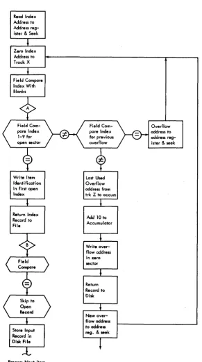
Indirect Addressing ... . . . 50
INTERNAL CHECKING... 63
380 CONSOLE ... . 68
CONSOLE OPERATING PROCEDURES ... . 78
Start-Stop Procedures ... 78
Inquiries ... . . . 79
Alterations to Drum Tracks. .. . . .. . . .. . . .. . . . ... . .. 80
Testing Procedures ... 80
380 CONSOLE TyPEWRITER... 82
Typewriter Control Panel ... 82
Operating Features ... ,. . .. .. .. .. .. ... .. 91
370 PRINTER ... 99
Operating Keys and Lights ... '" 100 Printer Control Panel ... '" 101
CONTENTS
Tape-Controlled Carriage ... . Operating Features ... . Form Control ... . Multiple Line Printing ... . Timing Chart ... . Page 108 113 115 120 123 323 CARD PUNCH ... 125Feed and Punch Unit ... '" 126 Operating Keys and Lights ... . 126
323 Control Panel ... . 127
Timing Chart ... 132
ERROR CORRECTION PROCEDURES .. Processing Errors ... . Printer Errors ... . 134 134 136 Punch Errors .. . . .. 137
WIRING AND OPERATING SUGGESTIONS. Wiring Rules ... . Wiring and Programming Suggestions ... . Operating Hints ... . 139 139 144 148 SPECIAL FEATURES ... 149
323 Punch.. .. .. ... .. .. . . .. . . .. . . .. .. .. .. .. . . .. . .. 149
Printer Output Track ... 153
305 Process Unit ... 153
Division ... 155
Additional 350 Disk Storage ... 160
Dual Access ... , ... " . . ... .. 160
CONTROL PANEL SUMMARy ... 167
RAMAC is a registered trademark that has been coined from the expression
®
Random Access Method of Accounting and Control. The IBM 305 is the first of a series of machines designed to approach in-line accounting on a mechanized basis. This approach requires the use of a storage device that permits rapid access to any of several million characters of data comprising the accounting records.
The IBM 305 RAMAC consists of the following machine units:
305 Processing Unit 323 Card Punch 340 Power Supply
RANDOM ACCESS METHOD OF
ACCOUNTING AND CONTROL
BEFORE the development of mechanized accounting, business records were maintained in a series of ledgers by clerks who posted each transaction to the proper accounts. For example, if a manufacturing company bought raw material, the clerk subtracted the cost of the material from the cash account and added the cost to the raw material account. This system of accounting was slow, and subject to clerical errors, but it had the inher-ent advantage that the accounts were constantly main-tained in balance.An important feature of this system of bookkeeping is that the clerk had access to all the accounts in random order. In the example just mentioned, the clerk changed the balances in the cash account and the raw material account. The next transaction could reflect the fact that some of the raw material had entered the manufactur-ing process, in which case the clerk would subtract this amount from the raw material account and add it to the material-in-process account. However, it is more prob-able that the next transaction would affect entirely dif-ferent accounts. Perhaps some of the finished products were sent to the wholesaler. This transaction would af-fect the inventory and accounts receivable balances. Be-cause the clerk has direct access to all of these accounts, he can complete the posting of each transaction before beginning the posting of the next. This accounting method is called in-line processing. In-line processing has previously not been practical in automatic account-ing systems because of the difficulty of reachaccount-ing and changing single records in large files. However, with the introduction of the IBM 305 RAMAC which is built around a random-access disk storage unit that permits the storage of 5,000,000 characters of business facts (the equivalent of 62,500 80-column IBM cards), in-line processing is now a practical reality.
IBM 305 RAMAC
The storage is organized into 50,000 100-character records which are used to store master information, and previous balances. For processing, the machine can obtain any of these 50,000 records without scanning through the intervening records.
These master and balance records may be considered roughly analogous to the ledgers used in the manual systems of accounting. Each record may contain the equivalent of the last entry to an open-item account. In general, the records should be thought of as the master files used in punched-card accounting. Repetitive infor-mation and balances are stored in the disk storage unit. The detail information is usually maintained on IBM cards. The machine performs all bookkeeping functions in posting transactions to the proper accounts. This fa-cility, and the ability to reach any of the records directly, permits the machine to perform in-line processing.
IBM PUNCHED-CARD APPROACH
FIGURE 1 shows a simplified flow-chart for the offset card order method of inventory control and invoicing, using conventional punched-card eiuipment. The orders, receipts and other transactions that will change the in-ventory are punched into IBM cards and verified. All orders are given a manual credit check. The stock editor determines whether an order can be filled, and files the transaction cards behind the corresponding balance cards in an oversize card tray, with the balance card and the transaction cards offset from the body of the file. At the end of the filing operation, the offset cards are manually removed from the file and run through an accounting machine that produces a transaction register and sum-mary punches a new inventory balance card. The revised inventory card is interpreted and refiled in the inventory balance file.The order cards and returns cards are sorted out and run through a calculator to obtain extensions. The
Order
Keypunch
024 and
Verify
Merge 077
Interpret 552
Material Accounting
Procedure
IBM PUNCHED CARD APPROACH
Keypunch
and 024
Verify
Acct. 407 Transaction
f---~ Register
Mach.
Calc. 602-A
407
519
L...-_...-_...I Sum. I---_~ Accounts Rec.
unch Cards
Shipping Documents
Statements
culated cards are assembled by hand with heading cards and run through the accounting machine to produce the invoice and other shipping documents. Simultaneously, accounts receivable cards are punched which are later used for billing. The source cards are sorted; the heading cards are returned to the file while the order cards enter the material accounting procedure.
This method of inventory control has been extremely successful. However, a considerable amount of manual editing and filing is required, and cards must be
pro-cessed through seven different machines.
IBM 305 RAMAC APPROACH
BECA USE the files are located in the machine! most of the preceding manual steps are eliminated when the same application is done on the IBM 305. Figure 2
shows the RAMAC approach. The cards are punched and verified as before, but because the machine will do the editing and credit checks, these steps are eliminated. The cards are placed in the input hopper, and the ma-chine, through programming,
1. determines availability of each item ordered,
2. prices each item,
3. adjusts stock balances in the memory, 4. prints out an invoice,
5. punches transaction cards from which a transaction register can be listed,
6. punches accounts receivable cards which can be combined with the transaction cards to list detailed statements,
7. punches a warning card whenever the balance of an inventory item drops below a predetermined level,
8. punches a order card for each item back-ordered, and
9. accumulates usage data, which can be unloaded at intervals for sales analyses.
Using the offset punched -card system, all the filing must be done before the cards are run through the ac-counting machine. Under the RAMAC system, the cards may be inserted at any time, without sorting.
The console, which is part of the RAMAC system, contains a keyboard and a typewriter that allow an op-erator to make inquiries into the status of any account in the disk storage unit. Because the accounts are constantly being posted, this inquiry allows the operator to obtain
a truly current balance almost instantly.
Because the machine can perform logical operations under the control of its program, such routine clerical functions as determining whether there is enough stock to fill an order, whether the stock has dropped below the re-order point, or whether the customer has exceeded his allowed credit can be performed automatically by the machine. For example, as each invoice is written, a credit check can be made to determine if the sale causes the customer's credit maximum to be exceeded. If the maxi-mum is exceeded, the machine can be programmed to print a signal on the margin of the form to indicate that the order requires the approval of the credit manager. In this way, only the exceptions must be reviewed man-ually.
Because of the huge storage capacity, it is possible to store entire price or rate tables in the machine for rapid reference. This facility allows the machine to price items or services on the basis of quantity ordered or amount used.
It is possible in many instances to store all the ac-counts of a business in the machine. The machine will perform all accounting functions on these records, up-dating them for each transaction. For example, the ma-chine could handle inventory control and billing as its primary application, producing accounts receivable rec-ords and sales analyses at intervals. The costs of new material added to inventory could be distributed to vendor accounts, which would be referred to at intervals for the determination of accounts payable. Periodically, the machine could prepare the payroll and distribute labor costs to the proper accounts.
Advantages
Transactions are posted as they occur. This leads to the availability of more timely information and closer control over business transactions. For example, in the inventory control application just presented, receipts are immediately entered into the inventory accounts and issues are immediately extracted. The item account there-fore constantly reflects the current balance of items on hand. Closer control over inventory results in reduced inventory charges and increased service to customers by reduced back orders.
Continuous in-line processing eliminates the need for transactions of a like kind to accumulate before making a run. This makes possible a continuous flow of orders through the office and warehouse, resulting in a much smoother operation and better service. The procedures made possible by the ability to store five million
Order
Keypunch and Verify
Keypunch and Verify
Inventory Customer Name & Address
Accounts Receivable Accounts Payable Payroll
Shipping Documents
Exception Credit Approval
Immediate Determination of the Status of any Account
Accts. Receivable
t - - - -..
Statements CardsBack Order Cards
Less than Mi n. Ba I Warning Cards
Transaction Cards
1 - - - - -.... To Purchasing
Transaction Register
Receiving Report
acters of information and to obtain them from storage at a high rate of speed may eliminate the need for sort-ing, collating and successive runs.
Random inquiry to any part of the stored record allows a truly current balance to be obtained for any
account almost instantaneously by an operator.
Current processing of minute-by-minute data means dynamic accounting instead of a history for management to review.
SYSTEM ORGANIZATION
ANY processing machine of this type has three general types of elements: input, processing and output. Raw information is fed into the machine through input units.
It is processed and digested in the processing unit, and
the results are obtained from the machine through the output units. These elements are present in all account-ing machines.
It is usual for the processing unit to have a control
section that determines the sequence of processing. An example of this type of control is the wired control panel, where the pattern of the wires determines the operations
that are performed. Another type of control is the stored
program that will be discussed later.
Figure 3 is a general diagram of the 305 system. In-formation is entered into the system through an input card reader. When called for by the control unit, this information enters the processing unit. Processing con-sists of assembling information for output documents, making logical decisions, and maintaining and updating the accounting records that are stored in the machine in the random-access storage. The results from the pro-cessing unit may be punched into IBM cards in the 323
PRINTED
OUTPUT
CARD ...
OUTPUT
Figure 3. General Diagram of the 305 System
Punch, printed on the forms passing through the 370 Printer, typed on the 380 Typewriter, and stored in the 350 Disk Storage Unit.
Operating Speeds
The operating speeds of the machine units will be quoted when the individual units are discussed. Some of the operating times will appear slow in comparison with other electronic machines. However, it should be
remembered that the 305 is an accounting machine with
calculating ability. Most operations may be overlapped, so the actual processing time has almost no relation to the time obtained by adding up the operating times of the individual components. For example, at a given instant the machine may be printing a line on an invoice, punching a transaction card, assembling the detail of the following transaction in the processing unit, seeking a record in the random -access storage, and reading in information from a card for later processing.
To determine the time required for a given program, it will be necessary to consider not only the component speeds but also the amount of overlapping that can be obtained. This can be determined accurately only when the application has been programmed. However, an indi-cation of the over all speed may be obtained from the programming of a number of typical applications in which the machine would completely process about 10,000 transactions in an 8-hour day. Methods of de-termining the exact processing time and of obtaining maximum overlapping of operations will be discussed
later.
Machine Components
Processing Unit. The processing unit contains a
mag-netic drum, on which there are storage tracks for pro-gram instructions, arithmetic and logic, and information being processed. The processing unit also contains a 100-character magnetic-core unit, that is used for all transfers of information, and the control circuits for the process-ing operations.
Card Reader. In general, the information to be entered
into the system is punched into IBM cards and entered through the card reader. The card reader is a parallel-type card feed containing two reading stations of 80 reading brushes each. Cards are fed face-down, 9-edge first. The feed hopper can hold up to 800 cards.
The card feed operates independently of all other input-output units. Cards are fed under the control of
the program. The maximum rate of feeding is 125 cards per minute.
As the cards pass through the reader, the 80 columns of information are read from the card, translated into the code used in the machine, and recorded on the input storage track on the magnetic drum in the processing
unit.
Output Printer. The 370 Printer may be used to pre-pare documents while the transactions are being posted in the machine. The printer is a serial printing device that prints from a single, octagonal type stick that moves rapidly across the form from left to right. The complete alphabet, the numbers 0-9, and 11 special characters may be printed. Horizontal spacing is 10 characters per inch, and an 8-inch line (80 characters) may be printed. To print an 80-character line requires approximately two seconds. Shorter lines are printed in less time.
The information to be printed is taken from an output track on the processing drum. A control is provided on the printer to allow the character stored in any output track position to be printed in any printing position. Line program selectors are provided on the control panel to allow a number of different printing arrangements ( formats) to be selected. The control panel also provides such functions as zone elimination, variable line-spacing, and special character insertion.
T ape-Controlled Carriage. A tape-controlled carriage controls the vertical movement of forms in the 370 printer. The forms tractors are adjustable horizontally to accommodate forms with a hole-to-hole width of up to 16Y4 inches. Continuous form paper with standard marginal punching must be used. The maximum length of a form to allow proper feeding is 17 inches.
Card Punch. The 323 Card Punch is used only as an output device, and punches up to 100 cards per minute, depending on the program. The punch receives its in-formation from the same output track that is used by the printer; it is possible to print and punch at the same time. Separate format control is provided for the punch, and by control panel wiring any 80 characters of the possible 100 characters on the output track may be punched. A complete 80-column card is punched in 600 milliseconds. It is possible to perform gangpunching, double-punch and blank-column detection, and opera-tions involving column-splitting and character emitting.
Magnetic Disk Storage. To perform in-line process-ing, the machine must automatically obtain any record it requires in a minimum of time. This ability is pro-vided by the magnetic disk storage. This unit consists of
50 metal disks, two feet in diameter, that are coated on both sides with a ferrous oxide recording material. These disks are mounted on a vertical shaft, and are slightly separated from one another. They revolve at
1200 rpm.
Information is stored in the form of magnetized spots in tracks around the disks. There are 100 concentric tracks on each disk. These tracks occupy the outer five inches of the disk surface.
At the side of the stack of disks there is an access arm that moves under electronic control to any desired track on any disk (Figure 4). Magnetic recording heads mounted on the access arm read or write information on the disks. The access arm is forked. When the fork enters the stack of disks it carries a recording head to both sides of the disk. When the arm is positioned on a disk it is possible to read or write on either side of the disk; therefore, a disk track may be thought of as exist-ing on both the top and bottom of a disk.
10 sectors on each track (5 on top, 5 on bottom)
100 Characters
Disk 00
\ Read/Write Heads
======;~=t=R=t=:=====~===~
-='J/{=
Disk 49The disk tracks are subdivided into sectors. There are ten sectors on a track; five on the top of the disk and five on the bottom. Each sector can store a 100-character accounting record. The record is stored as a series of magnetic spots recorded in the sector on the track. By storing ten 1 aO-character records on each of 100 tracks on each of 50 disks, it is possible to store 5,000,000 alphabetic, numerical or special characters in the unit. The magnetic disks can be used repetitively to store new information. Each time new information is stored in a sector it erases the information that was formerly stored there. Records may be read from the disks as often as desired, provided they are not written over or erased by the program.
Console. The console provides manual and
semi-auto-matic control of the machine. The console consists of a keyboard, typewriter, signal lights and control keys. The typewriter may be used for output of inquiries from the disk storage and process drum storage, or it may be used as a supplementary printer under the control of the pro-gram. The typing speed is 10 characters per second.
Associated with the typewriter is a control panel that
CHARACTER SELECTOR ADDRESS (HYPHEN)
J
R
STARTING DECISIONS BRANCHING
ENDING
establishes format control for the records that are typed on the typewriter.
The keyboard is similar to that of a typewriter. Through the use of the keyboard, inquiries for records are entered into the machine. The desired record is trans-ferred from disk storage to the typewriter track on the processing drum. From this track, the record is typed under the format established by the typewriter control panel.
The console contains a panel of indicator lights that continually display the status of the program in the ma-chine. This indicator panel serves as a valuable aid for checking and verifying the logic of the stored program. There are also lights that inform the operator that the machine has detected an error in the transfer of informa-tion through the system. The checking of informainforma-tion is discussed in a later section.
Overall Machine Schematic. The overall machine
con-figuration and data flow through the RAMAC system is shown in Figure 5. Each component (including track addresses which are shown adjacent to the arrows and indicated on the processing drum) will be described in detail in later sections.
MAGNETIC CORE UNIT
KEYBOARD
Figure 5. Summary of the 305 System
PROGRAM EXITS
:
~ ~ ~~ ~ ~ ~ ~ ~
o I 2 3u
ACCUMULATOR SIGN~ ~I~I! !,"UI~j~i'm~
6 7 8 - E - 9o 0 0 IN 0 0 0 0 IN a 0 0 0 IN 0 0 0 0 IN 0 0 0 0 IN 0 0 0 0 IN 0 0 0 0 IN 0 0 0 0 IN a 0 0 0 IN 0 0 0 0 IN 0 0
: I 1+1 I I 1+1 I I 1+1 I I 1+1 I I 1+1 I I 1+1 I I 1+1 I I 1+1 I I 1+1 I I 1+1 I
: I 1
01 I I 1
01 I I 1
01 I I 1
01 I I 1
01 I I 1
01 I I 1
01
I
I 1
01 I I 1
01 I 11
01 I
: I I-I I I I-I I I I-I I I I-I I I I-I I I I-I I I I-I I I I-I I I I-I I I I-I I
L OINO 0 0 - - - 0 - - 0 - - - 0 - 0 0 0 0 0 0 0 o-!!!-o o-!ho o--!!!..o o-!h.o oJ!!.o o-!h<:>[
AD/FLOW BUS IN A C 0 E F 2 CHARACTER SELECTORS M
I I I
0 - - - 0 - - 0 - - - 0 - ~ ~ 6 6 ~ ::, ~ o-!!-o ~ o-!!-o ~ o-!!.o 0-1-0N NO oaooooggbg~~60-!-!--0o--!-oo-!.!-oo--!-oo-!!-oo--!-o
P
I I I
0 - - - - 0 - - - - 0 - - - < g ~ ~ ~ 6 ~ a~K 0-2-0 o-!..o ~ o-!-o ~ o-!-o Q YES 0 - - - - 0 - - - - 0 - - - < 'g 6 ~ ~ ~ ~ ~ o-!-o ~ o-!-o o-Lo o-Lo 02-0R
f[
DO 0 - - - 0 - - 0 - - 0 - - 0 - 6 ~ gog ~ ~ o-!-o o--!-o o-!...o ~ o-!-o ~D
* - I , % * @5 0 - - - 0 - - 0 - - 0 - - 0 - 0 0 0 0 0 0 0 o--!-o ~ ~ o-!-o o--Lo o-.!-o
I 2 3 4 5 6 7 8 9 10 II 12 13 14 15 16 17 18 19 20 21 22 23 24 25 26 27 28 29 30 31 32 33 34 35 36 37 38 39 40
~ r~ ~ ~ ~ ~ ~ ~ ~
of,
~ ~ ~ ~ ~ '~TInT'~ ~ ~ ~ '~ ~ ~ ~ ~
!
~ ~ ~
o!,
~ ~ ~ ~ ~ ~
::
I~TfT!:!,:
: : : :
!T!TTPT!T~
: : : :
I~'!
: : : : :
.~
AR 10---0-0--- 1 o - - - o - - < > - < J 1 ~ 1 0 - - - 0 - 0 - 0 - - -1 0--0---0----1
8 1 - 8 5 - I N 9 5 - I
:: I I I I I I I I I I I I I I I I I I I I
OUTAU 0 0 0 0 0 0 0 0 0 0 0 0 0 0 0 0 0 0 0 0 AV 0 0 0 0 0 0 0 0 0 0 0 0 0 0 0 0 0 0 0 0
I PROGRAM ADVANCE·
AW ~O-HUNDREDSPROG.ENTRY-I_ ~ ~ 0----0--0---<> ~ RESET
AX I 0 - - 0 - - - 0 - - - - 0 - -I 0 - - 0 - - 0 - - - - 0 - 0 -I ~ ~ ~ 0----0----0---0
~
10 0 0 0 0 0 0 0 0 0-0 0 0 0 0 0 0 0 0
DI
~
10 0 0 0
0
0 0 0
o'Uo
0 0 0 0
0
0 0 0 01
BG BH BJ BK BL
8M
aN
8P
FOR THE GREATEST FLEXIBILITY of operation, the se-quence of processing is controlled by a stored program that is modified on the basis of logical decisions made through control-panel wiring.
Stored Program
The transmission of information through the machine is controlled by a sequence of instructions called program instructions, each of which performs some basic, neces-sary operation. As an example, suppose the machine has stored the information that 500 gallons of white paint are in stock. An order arrives for 15 gallons of white paint. In a manual system, a stock clerk would look at the paint and decide that the order could be filled. The machine makes the same decision by arithmetic. The way the machine makes this decision may be dia-grammed as follows:
A ADD THE QUANTITY ON HAND
B SUBTRACT THE QUANTITY ON ORDER
FILL THE ORDER
BACK ORDER
This sequence of instructions can be understood by anyone who reads English. However, the machine reads
Programming
a much more concise language called stored program coding. Instead of the English phrase, "add the quantity on hand," the machine reads a coded instruction or word something like W22L4905 that causes it to perform the required operation. The programmer can express as a series of these coded instructions all the steps that the machine must take to process the order. These program instructions are then loaded into the machine, and the machine reads the instructions and performs the se-quence of operations each time an order is to be processed.
Process Control Panel
When it is necessary to make decisions, the process control panel is used. The process control panel is shown in Figure 6. To facilitate reference to specific hubs on the control panel, the rows are numbered 1 through 40
horizontally and lettered A through BR vertically.
Shaded hubs indicate possible additional capacity for special features.
The decision elements, sometimes called logic ele-ments, of the machine are arranged as selectors on the process control panel. Whenever the machine must make a decision, the control of the program may be brought to the control panel as an electrical impulse. This im-pulse is wired through the selectors to perform logical decisions.
F or example, there are ten accumulators each of which has a sign selector arranged as shown in Figure 7. In each vertical row of hubs there is an IN hub, a pair of
hubs' marked
+,
a pair marked 0, and a pair marked-. When the accumulator is reset, or when it contains a zero balance, an internal connection is made between the
IN hub and the 0 hubs. When an amount is added into
the accumulator, the accumulator takes on a positive sign,
and a connection is made between the IN hub and the
+
To set up program to fi II order
To set up
program for ~I back order
I 6
Fig/ire 7. Method of Branching by Control Panel Wiring
hubs. When a greater negative amount is entered, the accumulator takes on a negative sign, and a connection is made between the IN hub and the - hubs. Only one of these three connections is made at anyone time.
In the example previously discussed, the program would be arranged so that after the stored program step, "subtract the quantity on the order," was completed, the control would be brought to the control panel as a Program Exit impulse. This impulse would be wired to the IN hub to test the sign of the accumulator. If the accumulator were positive ( 50 -15 gallons = 35 gallons) it would indicate that the order could be filled, and the test impulse, emerging from the
+
hub, would be wired to set up the first step of a sequence of instructions that would result in filling the order.A zero accumulator would indicate that there is ex-actly enough paint to fill the order, so this hub may be connected to the
+
hub to cause the same program step to be set up. A negative accumulator would indicate that there is not enough paint to fill the order; so if the test impulse emerges from the - hub, it is wired to set up the first step of a sequence of instructions that causes the item to be back-ordered.Automatic selection of machine routines in this manner is called branching. Note that the logic elements of the machine may be tested in combination, by wiring the test impulse through several selectors to set up one of a number of alternate program sequences.
Processing Drum
The processing unit contains a magnetic drum, on which the program instructions are stored. The drum also contains storage space for records being processed and updated, for input and output, and for other func-tions that will be described later. The drum revolves at 6000 rpm; it takes one revolution in 10 milliseconds
(.010 seconds).
A number of magnetic reading and recording heads are arranged along the length of the drum. Each of these is designed to read and write magnetic spots in a narrow band around the drum. These bands are called drum tracks. Each track is divided into 100 positions, and a single character of information may be stored in each position. Figure 8 shQws a graphic representation of a drum track where the track has been cut at the starting
point and unrolled from the drum. The 100 possible recording positions have been given addresses from 00 to 99. (An address is a group of characters specifiying a location in the machine.) The first character on the track is recorded in position 00; the second character is recorded at 01, etc., and the loath character is recorded at position 99.
Each position of a track will retain its information until new information is written in that position.
PROCESSING TRACKS
Four tracks on the drum are designed specifically for the storage of information being processed. These four tracks have the addresses W, X, Y, and Z. Each of these tracks contains 100 positions with addresses which range from 00 to 99. Therefore, the address Was locates the sixth character on process track W, and the address Z99 locates the last ( lOath) character on process track Z.
PROGRAM AND GENERAL STORAGE TRACKS (Figure 9)
Twenty tracks on the processing drum are arranged to store program instructions. Because each instruction
CARD, TRACK, OR RECORD
TR,£ICK 0 ST£POO 01 02 03
TR/ICK , STEP 10 /I 12 I , 13
I' " I I I ' I I I
I I '" "
0 5 0 15 0 25 30 35
TR,qCK 2 STEP 20 21 22 23
TR,qCK 3 ST£P30 31 32 33
"
requires ten characters, ten instructions are stored on each track. Up to 200 instructions may be stored on these 20 tracks at anyone time. When they are not required for the storage of program instructions, these tracks may be used as general storage tracks for the storage of other
information.
The 200 instructions are given numbers between 000 and 199 to, correspond with the order in which the ma-chine executes them. After executing any instruction, the machine proceeds automatically to the next higher-numbered instruction unless it is desired to skip to some other instruction. In this way, the program may advance from step 000 to step 199. After step 199, the program returns to step 000 unless it is transferred elsewhere. The method of making these transfers is explained later.
The program tracks are given the track addresses 0,
1,2,3,4, 5,6,7,8,9, &, A, B, C, D, E, F, G, H, and I. Program steps 00u. to 009 are recorded on track 0, steps 010 to 019 on track 1, etc. The chart shown in Figure 9 gives the locations of all of the instructions on the pro-gram tracks.
04 05 06 07 08 09
, , ,~'"'7, , , ,
,
,(~""" ,it, , " ",(;""
, , , (f, , , ,
, , , (F, , , ,
0 45 0 55 0 65 70 75 0 85 0 95
24- 25 2(, 27 28 29
34 35 36 37 39
, II , I I I I I I I I I I I I II 111111111 ,11111111 111111111 111111111 111111111 111111111 III fl~ III 111111111
TR,qcK 4- STEP 40 41 42 43 44 45 46 47 48 49
TR,qCK5 STEP 50 51 52 5"3 54 55 5(, 57 58 59
II II ILl Ll 111111111 I l l l l " " 111111'" " " " " I 111111111 111111111 111111111 1111'"" "'1,,"1
TRIJCK 6 ° STEt 60 0 (,/ 15 0 (,2 25 po 6:5 0 64 0 65 55 50 6t5 0 67 75 0 68 85 0 65$
TRACK 7 STEP 70 71 72 73 74 75 7("
III /I~III
78 79
1111111" 111111111 111111111 111111111 111111111 I
"""
""11111 111111111 111111111TR/JCK 8 STEP 80 81 82 83 84 85 8(, 87 88 89
TRACk' 9 STEP 90 91 92 93 94 95 % 97 98 99 " " ' " 1 1 1111'"11 1111'"'' 111111"1 111111111 1,1111111 111111111 111111111 111111111 111111111
TR,qCK
g
o ST£//OO 0 15 0 25 0 35 0 45 0 55 60 lot70 75 0 85 0 95
101 102 /03 104 105 /07 108 109
TR,qCI( II STEP/IO /11 112 113 114- 1/5 116 1/7 118 I 19
11111"" 111111111 111111111 II a l l i l l
""'''"
, , , , , , , , I1111'"11 111""11 " " " 1 1 1 1111'"11
TRACK B STEP /20 /21 122 12.3 124 125 126 /27 /28 129
TRACK C STEP /30 13/ 132 /33 Ildl~111
II ~1~1 III II (ft'llll II
If?I' "
, (1fl'""Ny,",
""'""
111111111 ""11"' 11111111'TRACK D °STE/140 0 /4/ 15 C /42 15 0 143 35 0 /44- 0 /45 55 bO 14-~5 0 /47 75 0 /48 85 0 149 95
TR,qCK E STEP 150 151 /52 153 /54 155 /56 1I1~~illl 158
II
iff
II 11 111111111 111/1 Llil III I " " 11111"" 111111111 111111111 11111-1'11 ""11111TRIKK F STEP 160 161 162 163 HA /(,5 If,,, 1(, 7 168 1('9
Ti?,qCK 6 STEP 170 171 172 173
II /?I~ III II /I~{ Lli 11
(Ztl1
L1 177, ,/?,8"" , ,(??, "
I 1 1 1 1 ' " " 11111111' 111111111 111111'11""""'
TRACK H o STE), 180 0
15 0 25 0 35 0 45 0 55 ~ 65 0 75 0 85 po 95
/81 182 183 184 185 /86 187 f8B 189
TRIKK I STEP 190 /9/ 192
, , /,~~ II I 194 I, ((151 I II II /?I~ III 111~nlll I I /I~~III III/I~[UJ 111111111 111111111 111111111 1111111,1
Figllre 9. Location of the InstflletiollS on the Program Tracks
I." , ,
I~~;I
"
"
,
,
"
,.I " " , , , ".I, , , , , , , ,
,.I " " ,
,,~~ I~,~ ~,~ ~
:
~ ~, ~,R, ~,~ ~, ,~,
" , ,
,I, , " , , " , I, , , , " " ,I
~9 19 29 39 49 59 69 79 89 99
100 - POSITION PART MAGNETIC-CORE NO.
UNIT
Figure 10. Schematic of a Normal Transfer Operation
Magnetic Core Unit
The stored program instructions control the flow of information through the machine much as a switchman controls the flow of trains through a railway junction. By the same analogy, the magnetic-core unit corresponds to the junction. The machine assembles information from various sources into a form that may be used for output by making a series of transfers of "pieces" of information. These transfers are accomplished by direct-ing data through the intermediate magnetic-core unit.
This unit is arranged to store from 1 to 100 characters.
Under control of the stored program, the desired infor-mation is read from a source track into the magnetic cores on one revolution of the processing drum and on the following revolution, the information is read from the cores and recorded in the specified positions of the receiving track. The cores serve as an intermediate stor-age unit on each transfer.
Unlike the processing drum tracks, data is transferred to the core unit starting with position 99 and extending for the number of positions being transferred. As the new information is read into the core unit, old informa-tion in those posiinforma-tions is erased. For example, a block
of data 40 positions in length would have its units
posi-tion in posiposi-tion 99, and its high order posiposi-tion in posiposi-tion 60. Positions 00-59 of the core unit retain their original
data. As described in a later section under Pro gram I
n-strnction, the core may
be
addressed by the designation hyphen (-).Program Instruction
The ten-character instructions are arranged as follows:
FROM TO
No.
Chor- Control acters
Track Position Track Position
I
I
I
I
The character in the first (left hand) p~sition of the
instruction specifies the track on which the desired in-formation is stored. The next two positions specify the position of the low order character of the information
on the track. These three positions ar~ called the FROM
address of the instruction. In a similar manner, the next
three positions are called the TO address and specify the
track and units position to which the information is being transferred. The next two positions of the
instruc-tion define how many characters (NO. CHARACTERS)
are to be transferred. The ninth and tenth positions are control positions of the instruction. Any of the 47 char-acters recorded in the ninth position will cause an im-pulse to be emitted on the process control panel for test-ing and branchtest-ing. The ninth position is also called the
As an example, suppose that it is desired to transfer a part number, recorded in positions 05-09 of processing track W, into position 29- 3 3 of process track Z. A field of five positions are read from track W into the
mag-netic cores, and then transferred from the cores onto track Z (Figure 10). The low-order position of track W is 09, and the low-order position of track Z is 33; there-fore, the necessary program instruction is:
FROM TO
No.
Char- Control aeters
Traek Position Track Position
W
01
9z-
31 3 0\5
\A normal transfer operation In the processing unit
requires 30 milliseconds (three drum revolutions) for completion. During the first 10 milliseconds, the in-struction is read from the program track into an instruc-tion register, analyzed, and used to set up the required paths for the transfer of information. This is called the
Instruction cycle. During the second ten milliseconds, the
information from the sending track is loaded into the magnetic-core unit. This is called the From cycle. The final 10 milliseconds are required to read out the core unit and record the contents on the receiving track. This is called the
To
cycle. In terms of the usual stored pro-gram concept, the first 10 milliseconds constitute theinrtmction cycle, and the next 20 milliseconds are the
execlIte cycle. If there is no control code in the ninth
position of the instruction, the machine immediately reads the next instruction, and the sequence is repeated. Note that each transfer passes through the core unit with the units position of the transferred data in the units position of the core unit (position 99) . Each posi-tion of the magnetic-core unit retains the last character transferred until a new character passes through that position. Data in the cores may be transferred by using a FRO M address of -99 (other than hyphen 99 will cause incorrect operation) .
Control Codes
If a control code is added to a program step in the ninth position, an additional 20 milliseconds is added to the 30 just described. During this 20 milliseconds, the control is brought to the control panel as an electri-cal impulse, which is used to test the logic elements and perform other functions. The additional 20 milliseconds
are required for the machine to step through two addi-tional cycles, a 1 O-millisecond delay and a 10-millisecond
exit cycle.
The ninth position control code may be any letter, number or special character. When a control code is added to an instruction (in the ninth character of the instruction), after the instruction has been performed an impulse is emitted from the correspondingly-marked hub on the process control panel. The control codes may be used in any order.
f
!
I I
1:1
0 - - 0 (
PROGRAM EXITS
-IIII!1lfl tiIIl
A-B, 1-36 C, 1-22
Program Exits. When a control code is placed in the
ninth position of an instruction, an electrical impulse is emitted from the correspondingly marked PROGRAM
EXIT hubs. Simultaneously, the program sequence is
halted. The impulse is used to test the logic elements on the control panel, and a new sequence of instruc-tions must be initiated by the impulse on the basis of their setting. The new sequence is established by wiring the impulse to the desired PROGRAM ENTRY
hubs.
rnr
- - T E N S --PROGRAM ENTRV--, :UNITS - -F1l
10
ODD 0
DOC:
0
0
U
Be-BF, 1-40
. . - - - P R O G R A M A D y A N C E - - - ,
AW, 1-20 AX, 1-20
Program Entry. These hubs accept a Program Exit
im-pulse to set up the first step of a new sequence. Unless a new sequence is started in this manner, or by im-pulsing PROGRAM ADVANCE. programming will stop with the DELAY and EXIT lights at the console on.
The new stored program step is set up by impulsing
a TENS hub and a UNITS hub that corresponds to the
number of the desired program step, provided that the step is in the same hundred steps (000-099 or
199) as the step that caused the program exit. For example, to transfer the stored program from step 32 to step 68, the instruction for step 32 would have a control code added, giving the instruction the form:
FROM TO
No.
Char- Control acters
Track Position Track Position
W I
\5
M
2\9 0\2
B \
When the instruction is completed, an impulse is
emitted from the PROGRAM EXIT B hub, and the
pro-gram sequence is halted. The impulse would be wired
(through distributors) to the PROGRAM ENTRY hubs,
impulsing TENS hub 6 and UNITS hub 8. This sets up
step 68 as the next step. The TENS and UNITS hub
must be impulsed simultaneously.
If the program is to be skipped to step 168, it
would also be necessary to impulse simultaneously the HUNDREDS PROGRAM ENTRY 1 hubs. Similarly, to
skip the program from step 132 to step 68, the
im-pulse emitted as a result of the control code on step
132 would be wired to impulse the HUNDREDS hub 0,
the TENS hub 6 and the UNITS hub 8. It is not
neces-sary to impulse the HUNDREDS PROGRAM ENTRY when
the program remains within the same hundred
pro-gram steps. Figure 11 shows how these transfers are
wired on the control panel.
Program Advance. When the program sequence is halted
by the presence of a control code in the ninth position of an instruction, it is frequently desirable to return
to the next program step. If the PROGRAM ADVANCE
hubs are impulsed instead of PROGRAM ENTRY, the
stored program resumes control on the next program
step. Figure 11 shows wiring in which the control
code K tells the machine to print the record stored on the output track and advance to the next program step.
r~ ~ ~ ~
!
~
P
nI~Tn ~ ~ ~ '!o~ ~ ~ ~ ~ ~ ~
r~! ~:p
!!
!
:"TJ
AJ-AM, 1-40 AN-AQ, 1-20
Distributors. Impulses that are used to perform several
functions are wired through distributors, which serve the same function 'as split wires, but prevent possible
back circuits. The impulse wired to the IN hub of a
distributor is available at the associated OUT hubs, but
impulses cannot travel between OUT hubs, or from an
OUT hub to the IN hub. Any impulse except that from
the OUT hub of another distributor may be wired
through a distributor. Whenever an impulse is di-rectedto more than one function, it should be wired through a distributor.
Input Track
Cards fed into the card reader are recorded on the
input track in positions 00-79. Positions 80-99 are
writ-ten as blanks. When the input has been checked, the data on the input track may be processed. The input track has the address K. This track is addressed in the same manner as the other storage tracks, for transfers under stored program control. Thus, to transfer the entire input track to the processing track Y, the instruc-tion is:
FROM TO
No.
Char- Control acters
Track Position Track Position
K
9\9
Y9\9
010
\
NOTE: A NO CHARACTERS of 00 denotes 100 characters. characters.
To transfer the first 50 positions of the input track
to the last 50 positions of program track 9, the
instruc-tion is:
FROM TO
No.
Char- Control acters
Track Position Track Position
K
4\9
99\9
5
I
0
\
NOTE: The instruction just shown indicates that the
input track may be used as a processing track, because it is possible to transfer part of the track without taking
the entire 100 characters. However, when the input
track is used in this manner it is not possible to feed the
COffi-, . - - - PROGRAM EXITS - - - . . . - - " " " T " " " - - - ,
·
o~ ~J ~ ~
I 2')
~ ~ ~ ~ 11~L1JJ,~I~rfft
3 ACCUMUL OR SIGN 6 7 8 - - E - - 9o IN 0 0 0 IN 0 0 0 0 IN 0 0 IN 0 0 0 0 IN 0 0 0 0 IN 0 0 0 0 IN 0 0 0 0 IN 0 0
I 1+1 I I 1+1 I I 1+1 I I 1+1 I I 1+1
I 1+1 I I 1+1 I I 1+1 I I 1+1 I I I+I I
I
1
01
I
1
01 I
I Iof
I
I 1
01
I
I 1
01
I
IoI I
I 1
01
I
I 1
01 I I 1
01 I
I IoI
I
4
0
I I-I
I I-I I I I-I
r
I I-I I I I-l
~
I I-I I I I-I I I I-I I I I-I I I I-I I
[
AD/FLOW BUS IN A 0 2 CHARACTER SELECTORS 5 6 1
o INO 0 0 0 0 o-!!!-<:> ~ o.!ho ~ o.!ho ol!!-o o.!ho o-!."!-o ~ o-!!!-<:> ~
•
;,:~;;~; ~ :!~,~
~~~~~~~~~
Q 6 6 6 .g" ~ o---!-o 0-2-0 o--!-o 0-2-0 0-'-0 o--!-o o--!--o 02-0 o--!-o o-!--o
~DDO
.. _
I • % If@o--!--<,O-!-Oo--!--<,O-!-OO-!--O o--!-o~
o--!-o o-!-o o--!-oI L
0 0 0 0 0 0 0 o-!-o o--!..o o--Lo o--!--o ~ o-!-o ~ o-!-o 0 l.o o--!..o[
I:~ANKO TR~~. 0 BUS~~A~TOCAR~ 0 I~----;;---;;CO~PA~E---I I~ 0 I 0 0 I 0 0 I F~ELDo ~O~PA~E I 0 0 I 0 0 I 0 ~N~INoI IINI
INoI I
I
1=1 I
f
I I 1=1
'f
1=1
Ir=~==:,
~ step 68 as the next program step to be taken. ~
W
IYESI I Iy I
IYESI I I I
tI
I
I
I I I
tI
I It
I
112. To skip from step 32 to step 168, control codeI
~
BUSjlP~oR. To~W CHS;0~Rf~IOP~t:3 ~sK:"i
\00
R;COR07D 0
8
0
9
~UT~
PU-~
~
o & 0 0 ~ ~ f
I
~ B would be wired to hundreds entry 1 as well ~2
toA;T;RIA~I~NtO;tO
T 0 61
6
~
as tens entry 6 and units entry 8.~
g 3 3 CI RESET DO-~ ~
AA = 0 0 0 ~ ~ 0 N 0 0 0 0 N 0 0 N 0 0 N 0 0 N f f ~ ~ ~
U 4 4 6 6 6 ~3. To skip from step 132 to step 68, control code ~
AB ~ 0 0 ~-I~~C~CL~ EOLAY~I~ c o o e 0 I~--=-I ~ U would be wired to hundreds entry 0, tens ~
:: nl!,
::78: :~
0 0",0 0 0 ;";1
0
1
01
0 °rouTIo
0
1
0' 0 : 1 entry 6 and unih entry 8.I
AE 6 6 0~4. Program exit K is wired to cause the machine ~
AF 0 - - 0 - - - 0 - - - 0 - - - 0 ~ to print the record on the output track and re-~
~ sume the program on the next program step. ~
0 - - 0 - - - 0 - - - 0 - - - o.~
0 - - 0 - - - 0 - - - 0 - - - 0 0 0 0 0 o e o l o e o 0 0 0 0 0 0 o e o l l AG
AH
I 2 3 5 6 7 8 9 10 II 28 29 30 31 32 33 34 35 36 37 38 39 40
I N - - - - . , - - - 3 0 - - - - I N - - - 4 0
11111111111111
OUT
a 0 0 0
o 0 0 0 a
AR AS AT AU AV AW AX AY
o
AZ
SA
BB BC
DOD
BD BE SF
Figure 11. Method of Wiring Program Transfers
pkted. Usually the entire input track is transferred to another processing track, and the feeding of another card is started while the first card is being processed. In this way, the time required to read the next card IS overlapped by the processing of the preceding card.
iol
AW-AX, 21-24
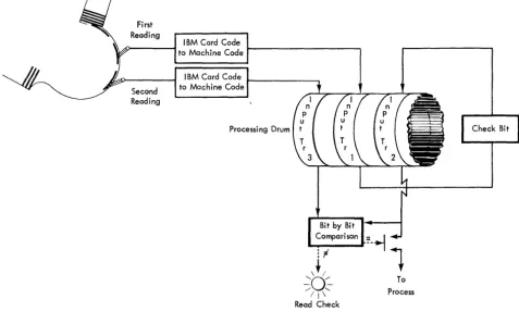
Feed Card. Impulsing these hubs causes the card reader to feed a card past each station. The card passing first reading is automatically coded and recorded on one input track. This recording is later transferred to an-other input track so that the recording may be com-pared against the reading of that same card as it passes second reading. If the two recordings compare (identical), the input track data may be processed. (See Internal Checking. Read Check.)
Output Track
The output track has the address S. When information is transferred to the output track, it may be printed on the 370 Printer or punched into IBM cards in the 323 Card Punch or both. Format control on these units de-termines the arrangement of the printing or punching.
The instruction to transfer the entire processing track Z to the output track is:
FROM TO
No.
Char- Control acters
Track Position Track Position
Z
91
9 S919 010
I
The instruction to transfer the first 32 positions of processing track Y to the last 32 positions of the output track is:
FROM TO
No.
Char- Control acters
Track Position Track Position
y
31 '
s
919
3\2
~
NOTE: This instruction indicates that the output track may be used as a processing track, because it is possible to assemble records on the output track. However, some loss of time may occur, because the output track cannot be altered while printing or punching is in progress. This facility is mentioned here because it may be of value when, due to a very involved program, all program and processing tracks are required for other storage. It is possible to read from the output track while printing or punching is taking place, but writing must wait until the track is released after printing or punching is com-pleted.
AW-AX, 25-28
Print. Impulsing these hubs causes the printer to print from the output track. The arrangement of the print-ing is determined by the printer control panel. The re-arrangement of data as it passes through the control panel from the machine to a printed or punched docu-ment is called format control. If two or more succes-sive impulses are directed to the Print hub without an intervening transfer to the output track, the second line will not print if the first line has not been com-pleted at the time of the second print impulse.
AW-AX, 33-36
PlInch. Impulsing these hubs causes the output punch to punch from the output track. Format control on the punch allows control of the columns that are being punched.
Typewriter Output
The typewriter may be programmed to type out in-structions to the operator or signals that unusual con-ditions have been encountered. For example, the type-writer may type out records that are out of stock or have fallen below minimum balance. It may also print out legends such as "item record not in memory."
record to track
Q,
the typewriter track. For example, to transfer the contents of track Y to track Q, the instruc-tion would be:FROM TO
No.
Char- Control acters
Track Position Track Position
y
9 19
Q9
I
9
010
FI
The program exit code on this instruction would be wired to TYPE on the control panel. (Further wiring is also necessary on the 380 Console control panel to cause typing. See 380 Console section. )
AW, 37-40
Type.
When the typewriter at the console is used to type an auxiliary document, impulsing these hubs causes the typewriter to type the information recorded on the Q track. Format control on the typewriter control panel determines the arrangement in which this in-formation is typed./ I I
III
II II
I I II I ITFROMI TO Ic~.1 IIIFROMI TO Ic=~ I 121FROMI TO 1d'i'.1 13 FROM I TO Ic~i.
I
I I
FROM To.T~. I I I FROM TO
I.
c':.".. 2 FROM TO l c::2.Track Clearing
It is often desirable to clear a track to blanks. This can be accomplished through programming by leaving the FROM track location of the instruction blank. For example, to clear track W to blanks, the following in-struction may be executed:
FROM TO
No.
Char- Control acters
Track Position Track Position
k
91 9
W91
9
01 0
I
LOADING THE PROGRAM
BEFORE RAMAC can start processing, program instruc-tions must be written on the program tracks (0-9, &,
A -I). The routine described is one of many possible approaches which may be used to transfer program in-structions from punched cards to the program tracks.
The processing instructions are punched into program load cards (Figure 12) with five instructions per card in columns 31-80. The first thirty columns of each card are set aside for the information necessary to direct the five instructions to the correct program track locations.
I
I I I II
I
I IIT
I I I II
I I I I 41FROMI TO Ic:t.~ 15 FROMT TO "~~RllsIFROMI ToTc":.'iar T71FROMI TO Ic~1 leiPROGRAM LOADING CARD IBM 305 RAMAC
®
I
I
TTT
1
I I I I I I ITFROM TO C~~R 4 FROM TO c~~' 5 FROM I TO I C::~.T TsT FROM I TO CH.... 171 FROM I TO I c::'t. r Tel 1 2 3 4 5 6 7 8 9 10 II 1213141516171819 10 2111 23 14 1526272829 30 3132 33 34 35 3637383940 41414344 45 46 4748 49 50 51525354 55 56 57",596061626364 65 66 67 68 69 70 7172 7374757677 T8 79 30
PRSOTGERpAM FROM PROGRAM STEP TO BE L~oA~fED ~ORDI PNRUOMGBREARM FROM PROGRAM STEPS FOR LOA?~N~ WORD
TO CHARAeT[R~ CONTROL CONTROL NO. I TO CHARACTUS CONTROL C~TROl NO. INTERPRET
4 ONLY ISM '57 WIT~ I
5 2
6 3
7
COMMENTS
8
CARD NO. PROGRAM NAME
r WORD I I WORD 2 I WORD 3 WORD 4 I WORD 5 I WORD 6 I WORD 7 I WORD 8 IFROMI TO INO.IIIFROMI TO NO. IIFROMI TO INOII FROM TO INOIIIFROMI TO INOII FROMI TOINOIT1FROMI TO rNoT FROMI TO INOII rl 2 3 4 5 6 7 8 9 10 II 1113114151611 II 1920 2121 23 241516 21 28 29 30 31 313334 35 36 31 38 391401414143144 45 4814) 48149150 5152 5.J/54 55 56157 581591601616263164 65 66167 68169170\71 72 73174 15 16T17 iifigTIO
11M 439410
\~============~F=============3A~======================~p========================#(
V VInstructions in these Control the Loading of the Five
Columns Program Instructions in these Col umns
FigllJ'(! 12. Card Ured for Program Loading
Figure 13. Program Load Button
The Program Load button (Figure 13) is used to feed Program Load cards into RAMAC. When the first card has passed the second reading stations and all input
1 . Card recorded on input track after being fed in by Program Load button. Program Load button causes automatic COPY IN.
COpy
checking has been satisfied, an automatic transfer occurs which moves the input data to the I track (an automatic K9919900) .
Z, 7-8
As soon as this transfer has been completed, an im-pulse is available (30 milliseconds later) from the COpy 0UT hub on the Process Control Panel which is wired to
feed a new card, and programming is directed to step 190 (track I, Figure 14). Step 190 will contain the same instruction that was in columns 1-10 of the input card. This instruction will cause the five steps on track I in position 30-79 to be transferred to the proper program
OUT ~---,
2. The automatic'COPY
I N, obtained by depressing the Program Load Button, causes an automatic transfer of track K to I. COpy OUT directs programming to step 190, and feeds a new card.
3. Program step 190 transfers the program instructions to the correct program track and the * in the program exit position impulses COPY IN.
COPY
IN
Figure 14. Program Loading
After transfer of K to I which is caused by COPY IN,
track. For example, if the card contained instructions 00-04, step 190 would be:
FROM TO
No.
Char- Control acters
Track Position Track Position
I
7\9
041
9
5\0
* \
This instruction would transfer
so
characters from track I to track O.. Instruction 190 also contains an
*
in the ninth posi-tion. This program exit is wired to COpy IN. The COPY IN hub has the same function as the Program Load but-ton and when impulsed, causes an automatic transfer from track K to I after the first card. By impulsing COPY IN, the next card is transferred to track I and the routine repeats itself.Card Number Load Instructions
It is usually desirable to type out a listing of the in-structions as they are loaded to verify the load routine. In order to accomplish this, the
*
is deleted from the instruction in column 1-10 of the second card. After in-struction 190 has been executed, the program advances to step 191 which corresponds to columns 11-20. This instruction transfers the assembled program from the program track to the typewriter track and a program exit of "&" causes a TYPE and COPY IN (099Q9900&).The following sequence is then established:
1. The first card assembles five instructions In the
first five instruction positions of program track
o .
2. The next card assembles the remaining fiveinstruc-tions on track 0, and then transfers all ten instruc-tions from 0 to the
Q
track so that they can be typed out on the Console typewriter.3. Subsequent cards load program instructions onto track 1-9, &, A-I, and, as these tracks are
com-Program Instructions
~~~~~~9VF~~~~~~A~~~~~~~~~~===F=~~~~~~~~~~
Instructions in these Columns
Control the loading of the Five Final Program Instructions in these Columns
Figure 15. Program Instructions tor Loading the Program
r - - - -PROGRAM EXITS - - - , - - - r - - - - ,
I!IIIIIItf!IIIIrI
R s T u• 1:1 - / 0---0 0---0 0---0 0---0
O---,~- , r 2 , r
-° ° IN ° o IN ° ° OIN ° ° ° olNo o alH 0 0
I 1+1 I I +1 I I 1+1 I I 1+1 I I 1+1 I
I 1+1 I I 1+1 I I 1+1 1 I 1+1 I
I 1
01 I I I I 1 I 1
01 I I 1
01 I I 1
01 I 1
01 1 1
01 I I 1
01 1 I 1
01 1 11°1 I
I I-I I I 101 I I-I I I I-I I I I-I I I I-I I I-I I I I-I I I I-II I I-I I
[
AD/FLOW BUS ' N ! £ Q ~ ~ _ 'N _ 2 ~ CHARACT R SELECTORS 5 6 7
M ;
°yN'EN:;O
0:
0 -
~////////////////////////////////////////////i., .,
~~
o-!!!.oB
o--!!!-<J~
01!!.0~
o-!!!--o o-!!::.o o.!!!-o~
~ ~
~ ~
~ PROGRAM.
0
~~LOAD
II
~~ BUTTON ~
ro
OO'g' ~~, - n u _ _ _ _ _ _ _ --~
o-i-o oE-o 0--1-0 0-!1-0 o-i-o ~ o-i-o
o-!-o 0--'-'---0 o--Lo ~ ~ o--'-!--D ~
o-!-o o-l1-o 0-£.0
°
6°
6 0 - - 0 0 - - 0 0 - - 0 0 - - 0o--Lo o-!-o 02-0 , 7 o-!-o 02-0
0 - - < ) 0 - - 0
~////////////////////////////////////////////~ o--!-o o-!--o o--!-o o--!-.o o-!--o 0-1--0 o-!--o o---!--<, o--Lo o--!-o ~-o o--!-o o--l-.o o--!--o. o.L.o o--!-o
T °IN'Noo 1
°1 °1 N'N
o1
° ° , ° I 0 2 0 I 0 3 ° I 0 4 0 I 0 5 0 I 0 6 ° I ° , 0 I 0 • 0
~
l
~~hWhW~~hWA0Y#~.$~[
BLANK TRAN ~BUS ~-,----'N FIELD COMPARE IN
~
1. The program load button initiates an automatic~
W 1YESI
I
IYESI 1~ copy IN which causes the first input card to be ~~ ~ automatically transferred to track I. ~
: :
~
BUS1~~:N
P:Oo:R.T4~W :~
.-;;--If--:::--.- - -1~
~
2. When the copy has been completed, the copy~
~
O--~ OUT hub emits; this is wired to start the pro- ~1 1
~ gram at step 190 and feed a card. ~~
~
ff1i ·
'0,i!!
3. The astedsk cont.ol code ;s w;,.d to COPY IN.~
~
I!
III
~ ~
I
~
I I I I I I I I I I
:
~
4.!~: ~6;;~~d.
cont.ol code ;s w;,ed~
TYPEI
, - - r -REC AOV-1'2\
~ ~AG I ~ ~ ~o-o-o---o c~ 5. The percent control code is wired to TYPE. ~
AH
I
~
I~
l
~-o--o--o--<o
~
~
_______ ~---~~-~---~~c~
3 4 8 9 10 II 25 26 27 28 29 30 31 32 33 34 35 36 37 38 39 40
~ I~
!
!
!
f
! !
!
1: : :
!
! !
OUT--~----25 30 IN 40
11111111111111111
o 0 0 0 0
:I~:::'
AR AS AT
AU ° 0 0
AV 0 ° ° ° ° 0 0
AW
AX
55
1111111111
OUT
O----O---O--<>-~
- - - -
OISTRIBUTORS---1111111111
OUT0000000
DDDDDDDDDI
AY AZ
SA BB
~
10
0
DOD
Don
D"~
U "0 0 0
0
0
0 0 0
01
pleted, they are typed out to prove that the pro-gram is loaded correctly.
Figure 15 shows the load card arrangement. Every other card transfers the assembled instructions from the program track for typing.
To load the full 200 program steps, cards 39 and 40 ( Figure 1 5) assemble steps 190-199 on processing track W. On step 191, track W is transferred to the typewriter track (Q), and on step 192 track W is transferred to track I, erasing the control instructions. The control code
"o/(J"
on the last step brings the control to the con-trol panel, where it is wired to type the last 1 0 instruc-tions, but because no new program step is initiated by impulsing Program Entries, the machine will stop after this instruction. The necessary control panel wiring for program loading is shown in Figure 16.Disk Storage
Two steps are required to read or write information in disk storage. First, the access arm must be moved from wherever it happens to be standing to the disk, track and sector that contains the desired record. When the access arm reaGhes the record, the record must be transferred through the magnetic-core unit to the process drum if the record is to be read, or from the process drum to the disk if the record is to be written in the disk storage (Figure 17) .
ADDRESSING
Records stored in disk storage are located through an associated 5-position address register, that may be
thought of as a "phone number" for the information. The 5-position address is arranged thus:
DISK TRACK REC.
NUMBER NUMBER NO.
0 0 0 0 0
to
4 9 9 9 9
The two high-order digits specify which of the 50 disks is to be used. The disks are numbered from top to bottom with the addresses 00 to 49. The next two digits specify which of the 100 tracks on the disk is desired. The tracks are numbered 00-99 from the outside in. These four digits are used to position the access arm.
Because the arm is forked, when it is positioned on a disk and track it can read any of the ten records (five on the bottom and five on the top of the disk) that may be stored on the track. The low order digit of the address specifies which one of the 10 sectors available at that physical location is to be used. The sectors are numbered 0-4 on the top of the disk and 5-9 on the bottom. This addressing arrangement provides 50,000 sectors having addresses from 00000 to 49999. Thus, the address 12345 causes the access arm to move to disk number 12, track number 34, and read out record number 5. Trans-mission of the address to the address register initiates the movement of the access arm.
The address register has the address
'T'
in the stored program coding structure. To move the access arm to a desired record, the address of the record is transferred toDISK NO.
TRACK REC.
DI$K STORAGE
,.-I
I
I
I
I
NO. NO.
INSTRUCTION THAT SENDS ADDRESS TO ADDRESS REGISTER POSITIONS ACCESS ARM ADDRESS "R"
WHEN ARM IS POSITIONED, RECORDS MAYBE READ FROM OR WRITTEN INTO THE MEMORY
R
PROCESSING UNIT
J
Figure 17. Method of Addressing, Reading and lVriting in Disk Storage
the address register. For example, if the address of the desired record is recorded on the first five positions of process track W, the instruction to move the access arm to that record is:
FROM TO
No.
Char- Control acters
Track Position Track Position