International Journal of Engineering Research and Development
e-ISSN: 2278-067X, p-ISSN: 2278-800X, www.ijerd.com
Volume 2, Issue 11 (August 2012), PP. 51-59
Maximum Boost control of Cascaded MultiLevel Z-Source
Inverter for Fuel Cell Applications
Dr.R.Seyezhai
1, Dr.B.L.Mathur
2& A.ShanmugaPriyaa
31
Associate Professor, 2Professor & 3PG Scholar, Department of EEE, SSN College of Engineering, Chennai, India
Abstract––In this paper, a cascaded five level Z-Source inverter is proposed for fuel cell applications. The proposed topology employs Z network between the DC source and inverter circuitry to achieve boost operation. The output voltage of proposed inverter can be controlled using modulation index and shoot through state. Various modulation strategies have been reported in the literature for the proposed topology. But this paper focuses on the implementation of maximum boost control with third harmonic injection which turns all traditional zero states into shoot-through states. The performance parameters of Z-Source cascaded Multilevel inverter is computed and compare with simple boost method. Simulations of the circuit configuration of the control methods have been performed in MATLAB/Simulink and the results are verified.
Keywords––Cascaded Z-source Multilevel Inverter, Maximum boost control, voltage stress & voltage gain..
I.
INTRODUCTION
In recent years, the multilevel voltage inverter is widely used in high power applications such as large induction motor drives, UPS systems and Flexible AC Transmission Systems (FACTS). Multilevel inverter obtains a desired output voltage from several levels of input DC voltage sources. With an increasing number of DC voltage sources, the inverter voltage output waveform level increases. As compared to traditional two level inverters, the multilevel inverters have more advantages which include lower semiconductor voltage stress, better harmonic performance, low Electro Magnetic Interference (EMI) and lower switching losses. Despite these advantages, multilevel inverters output voltage amplitude is limited to DC sources voltage summation. Occurring of short circuit can destroy multilevel inverters. To solve these problems, cascaded multilevel Z-source inverter [1-2] is proposed in this paper. The performance of the inverter is analyzed by employing a maximum boost control with third harmonic injection PWM technique. Maximum boost control converts all traditional zero states to shoot through while maintaining the active states. In this technique, the shoot through duty ratio varies during each cycle and maximum gain is obtained. Simple boost and maximum boost control methods for the proposed inverter topology are analyzed and compared .The effect of voltage gain and voltage stress for various modulation indices is studied for both the methods and the results are verified.
II.
CASCADED MULTILEVEL Z-SOURCE INVERTER
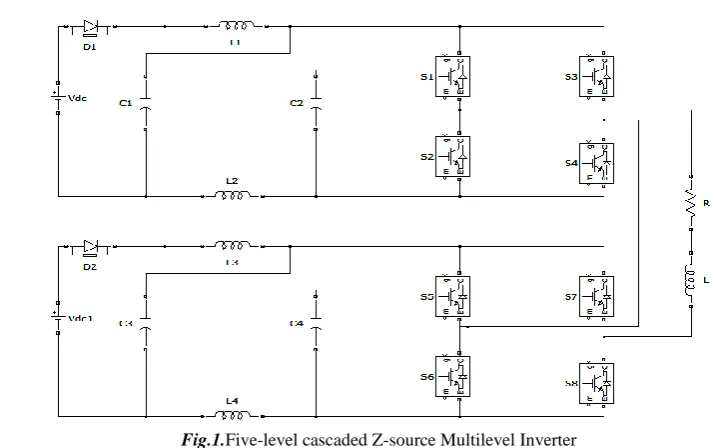
Fig.1.Five-level cascaded Z-source Multilevel Inverter
Circuit operation consists of two modes namely shoot -through and non shoot-through states [2]. In Shoot-Through (ST) switching state of Z-Source MLI, upper and lower bridges of the same leg is turned on having the output voltage of zero .During non shoot-through state opposite pairs of legs of both the bridge conducts. In ST state the two inductors are being charged by the capacitors and in Non-Shoot-Through (NST) states the inductors and input DC source transfer energy to the capacitors and load. This process is similar to the boost converter. Output voltage depends on the boost factor. The conduction table is shown in table –I
Table –I Conduction Table for Cascaded Multilevel Z-source Inverter
VOLTAGE LEVEL OUTPUT VOLTAGE ON SWITCHES
Level 2 (non shoot-through) 2Vin S3,S4,S5 ,S6
Level 1 (non shoot-through) Vin S1,S3,S5 ,S6
Level 1 (shoot-through) Vin S1,S2, S3, S4, S5, S6
Level 1 (non shoot-through) Vin S3,S4,S5 ,S7
Level 1 (shoot-through) Vin S3,S4,S5 ,S6, S7, S8
Level 0 (zero state) 0 (V) S1,S3,S5 ,S7
Level 0 (shoot-through) 0 (V) S1,S2,S3 ,S4,S5,S7
Level 0 (shoot-through) 0 (V) S1,S3,S5 ,S6,S7,S8
Level -1 (non shoot-through) -Vin S1,S3,S7 ,S8
Level -1 (shoot-through) -Vin S1, S2, S3, S4, S7,S8
Maximum Boost control of Cascaded MultiLevel Z-Source Inverter for Fuel Cell Applications
into shoot-through state [4-6]. The voltage stress across the switching devices is greatly reduced by fully utilizing the zero states. Turning all zero states into shoot-through state can minimize the voltage stress and this causes a shoot-through duty ratio varying in a line cycle, which causes inductor current ripple.
Maximum shoot-through boost factor can be written as,
(1)
Where B is boost factor and D is duty ratio which is given by
2
3
3
2
D
(2)
The circuit is in shoot through state when the triangular carrier wave is either greater than the maximum curve of the reference signals or smaller than the minimum of the references [7,8]. The shoot-through duty cycle varies each cycle. The shoot-through state repeats periodically in every п/3 degrees. Fig.2 shows the reference and carrier waveforms for maximum boost control with third harmonic injection PWM technique. The circuit is in shoot through state when the triangular carrier wave is either greater than the maximum curve of the reference signals or smaller than the minimum of the references. The shoot-through duty cycle varies each cycle.
Fig.2 Maximum Boost control with third harmonic injection
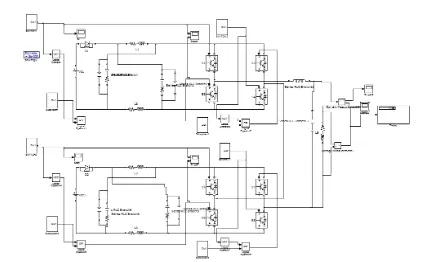
Fig.3 shows Matlab/ Simulink of Z-Source cascaded MLI using Unipolar PWM with Boost factor = 1.25, ma = 0.8,
RL Load where R=50Ω and L=24mH, Input voltage Vdc=75V, Z impedances, L1 = L2 = L3 = L4 = L = 40mH and C1 = C2 =
C3 = C4 = 6600µF. Simulink circuit is shown with LC filter having L=30mH and C=150µF.
D
B
2
1
1
Fig 3MATLAB/ SIMULINK circuit of Z-Source cascaded MLI using Maximum Boost control
IV.
SIMULATION OF CASCADED Z-SOURCE INVERTER USING MAXIMUM BOOST
CONTROL WITH THIRD HARMONIC INJECTION
The simulation results for the Z-source MLI with maximum boost control is shown in Figs.4,5 &6.
Maximum Boost control of Cascaded MultiLevel Z-Source Inverter for Fuel Cell Applications
Fig 5. Filtered output voltage waveform for Z-Source MLI
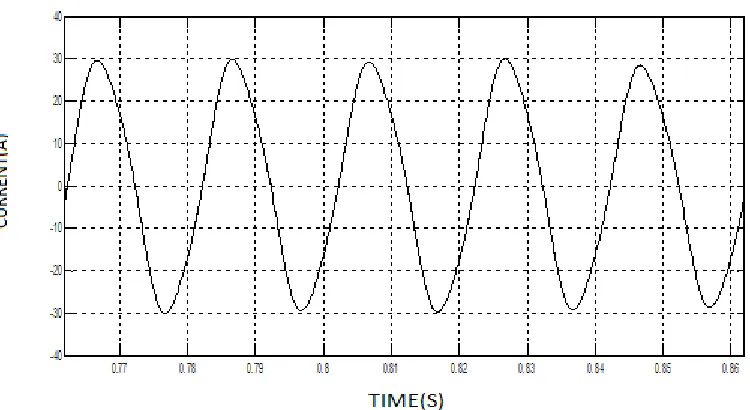
Fig .6Filtered output current waveform for Z-Source MLI
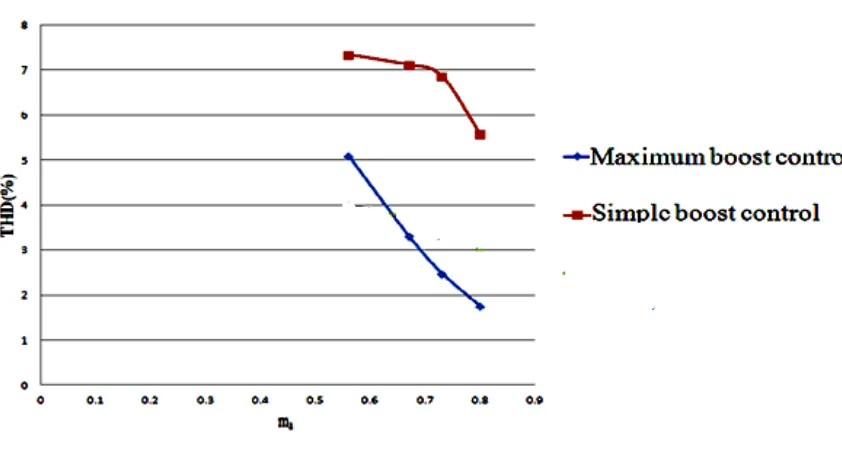
Fig .7 Effect of modulation index on Total Harmonic Distortion for three control techniques
From Fig .7, it can be concluded that the maximum boost control technique has reduced THDv compared to
simple boostfor ma=0.8. Inductor current ripple is calculated across the inductor of z impedance of Z-Source inverter. Inductor current ripple is shown in table for various modulation strategies that changes with variation in modulation indices.
Table I Effect of modulation index on inductor current ripple for three control techniques S.N0 m
a
SIMPLE BOOST
CONTROL METHOD
MAXIMUM BOOST CONTROL METHOD
1 0.8 0.5 0.0598 2 0.73 0.6191 0.0680 3 0.67 0.7 0.0796
From the Table I, it is clear that maximum boost control has less inductor current ripple than simple boost control method. Capacitor voltage ripple is calculated across the capacitor of z impedance of Z-Source inverter. Capacitor voltage ripple is shown in table -II for various modulation strategies that changes with variation in modulation indices.
Table II Effect of modulation index on Capacitor voltage ripple for three control techniques S.N0 m
a SIMPLE BOOST
CONTROL METHOD
Maximum Boost control of Cascaded MultiLevel Z-Source Inverter for Fuel Cell Applications
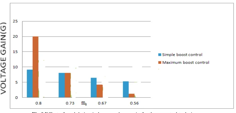
From the Fig 8 , maximum boost control technique has higher voltage gaincompared to simple boost control method for ma=0.8.
Fig 8Effect of modulation index on voltage gain for three control techniques
In Figures 8, 9 and 10, voltage stress in compared with voltage gain for various modulation techniques. Voltage Stressis calculated from voltage gain as shown in equations (4-6). Voltage stress is given by [15],
Simple boost control: - VS =
G
1
2
(4)Maximum boost control: - VS =
G
1
3
(5)
Maximum constant boost control: - VS =
G
3
3
(6)
Where, G=Voltage gain
Fig.9 to Fig.10 shows variation of voltage stress with voltage gain(G) for all three techniques.
Fig 10 Effect of voltage gain on voltage stress for maximum boost control method
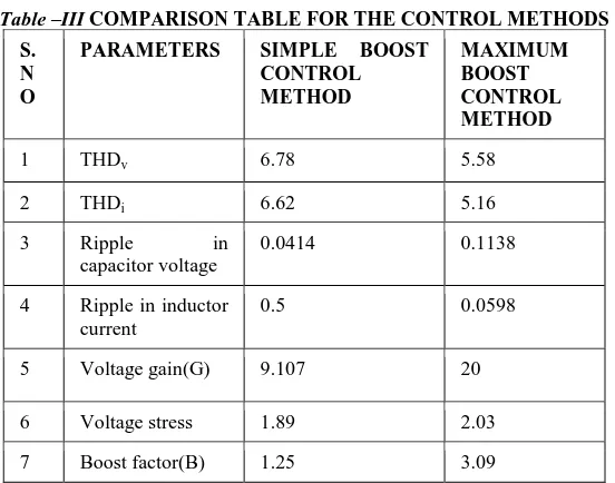
Table –III COMPARISON TABLE FOR THE CONTROL METHODS S.
N O
PARAMETERS SIMPLE BOOST CONTROL METHOD
MAXIMUM BOOST CONTROL METHOD
1 THDv 6.78 5.58
2 THDi 6.62 5.16
3 Ripple in capacitor voltage
0.0414 0.1138
4 Ripple in inductor current
0.5 0.0598
5 Voltage gain(G) 9.107 20
6 Voltage stress 1.89 2.03
7 Boost factor(B) 1.25 3.09
From the Table III, it is observed that the maximum boost control method has less Capacitor voltage ripple which reduces the cost of the capacitor used and gives high voltage gain (G) and reduced voltage stress (VS) compared to simple
boost control.Inductor rating of maximum boost control method is reduced with third harmonic injection PWM technique and also ripple in the output current reduces thus reducing the cost of the filter. With this maximum boost control method, THD of the output voltage waveform has been reduced. Therefore maximum boost control method is preferred for the proposed topology.
V.
CONCLUSION
Maximum Boost control of Cascaded MultiLevel Z-Source Inverter for Fuel Cell Applications
[6]. P. C. Loh, F. Gao, F. Blaabjerg, and S. W. Lim, “Operational analysis and modulation control of three-level
Z-source inverters with enhanced output waveform quality, ” IEEE Trans. Power Electron., vol. 24, no. pp. 1767–1775, Jul. 2009.
[7]. P. C. Loh, D. M. Vilathgamuwa, Y. S. Lai, G. T. Chua and Y. W. Li ,“ Pulse width modulation of Z-source inverters” , IEEE Trans. Power Electronics, Vol. 19, NO.3, pp.732-738, 2006.
[8]. P. C. Loh, D. M. Vilathgamuwa, C. J. Gajanayake, L. T. Wong and C. P. Ang, “Z-source current-type inverters: digital modulation and logic implementation”, IEEE Trans. Power Electron., vol. 22, pp. 169-177, 2007.
[9]. P. C. Loh, F. Gao, F. Blaabjerg and S. W. Lim, “Operational analysis and modulation control of three-level
Z-source inverters with enhanced output waveform quality”, in Proc. EPE’07, pp. 1-10,2007.
[10]. F. Z. Peng, M. Shen, and Z. Qian, “Maximum boost control of the Z- source inverter,” IEEE Trans. Power Electron., vol. 20, no. 4, pp. 833–838, 2006.
[11]. P. C. Loh, B. Flaabjerg, S. Y. Feng and K.N. Soon, “Pulse-width modulated Z-source neutral-point clamped inverter,” in Proc.IEEE. APEC’05, pp.431–437, 2005.
[12]. F. Z. Peng, A. Joseph, J. Wang, M. Shen, L.Chen, Z. Pan, E. Oritz-River and Y. Huang, "Z-source inverter for motor drives," IEEE Trans. Power Electron., Vol. 20, No. 4, pp. 857-863, 2005.
[13]. A. Keith Corzine, W. Mike Wielebski, Fang Z. Peng and Jin Wang, “Control of Cascaded Multilevel Inverters”,
IEEE Trans. Power Electronics, Vol. 19, NO. 3, pp.732-738, 2005.
[14]. F. Z. Peng, “Z-source inverter”, IEEE Trans. Ind. Appl., vol. 39, pp. 504-510, 2005.
[15]. M. S. Shen , J. Wang and F. Z. Peng , “Maximum constant boost control of the Z-source inverter”, IEEE Industry Applications Society Annual Meeting,pp.142-147,2003.
Biography
Dr.R.Seyezhai obtained her B.E. (Electronics & Communication Engineering) from Noorul Islam College of Engineering, Nagercoil in 1996 and her M.E in Power Electronics & Drives from Shanmugha College of Engineering, Thanjavur in 1998 and Ph.D from Anna University, Chennai, in 2010. She has been working in the teaching field for about 14 Years. She has published 100 papers in the area of Power Electronics & Drives. Her areas of interest include SiC Power Devices & Multilevel Inverters.
Dr.B.L.Mathur obtained his B.E. (Electrical Engineering) from University of Rajasthan, in 1962 and his M.Tech in Power Systems from IIT, Bombay in 1964.He completed his Ph.D. in 1979 from IISc, Bangalore. His Ph.D. thesis was adjudged as the best for application to industries in the year 1979 and won gold medal. He has been working in the teaching field for about 44 Years. He takes immense interest in designing Electronic circuits. He has published 50 papers in National and International journals and 85 in National and International conferences. His areas of interest include Power Devices, Power Converters, Computer Architecture and FACTS.