ISSN(Online): 2319-8753 ISSN (Print): 2347-6710
I
nternational
J
ournal of
I
nnovative
R
esearch in
S
cience,
E
ngineering and
T
echnology
(An ISO 3297: 2007 Certified Organization)
Website: www.ijirset.com
Vol. 6, Issue 6, June 2017
Performance Analysis of Digital Controller for
BLDC Motor Drive System
S.Raja1, Dr. M.Rathinakumar2, A. S. Viswanathan3
Asst. Professor, Dept. of EEE, SCSVMV University, Kanchipuram, Tamil Nadu, India13
Professor, Dept. of EEE, SCSVMV University, Kanchipuram, Tamil Nadu, India2
ABSTRACT: In this paper the performance of BLDC Motor under loaded condition using PI Controller and Fuzzy controller is analysed. The mathematical model of the BLDC motor also is developed and the performance of controllers for given BLDC motor is compared. At first a simple and conventional PI controller is developed for the speed control of the given BLDC motor. Then a fuzzy logic based PI controller is developed. Fuzzy logic controller is more robust to the variations in plant parameters. The Matlab Simulink tool was used to simulate the proposed system. Through extensive simulation results, it is observed that fuzzy logic controller gives better performance compared to conventional PI controller.
KEYWORDS: BLDC Motor, PI controller, Fuzzy.
I. INTRODUCTION
In the recent years, demand of high efficient electric motors is growing rapidly in the field of residential application like refrigeration, air conditioner, fans and washing machine. Many researchers made effort to develop highly efficient motors for the above mentioned applications. Conventional motors having low efficiency, poor dynamic response and hence to overcome these problems special machines get the attraction towards meeting the industrial needs.
The variable speed drives applications mostly uses Induction motor as they are cheaper, require less maintenance, and operates at high speed. The induction motors are having slip power losses and runs at lagging power factor so that it is not an highly efficient motor when compared to the special machines like Brushless DC motor, Permanent magnet synchronous motor and switched reluctance motor. The BLDC and PMSM drives are getting more popular because of high efficiency, low noise, high operating speed, high power to weight ratio and reduction of electromagnetic interference
ISSN(Online): 2319-8753 ISSN (Print): 2347-6710
I
nternational
J
ournal of
I
nnovative
R
esearch in
S
cience,
E
ngineering and
T
echnology
(An ISO 3297: 2007 Certified Organization)
Website: www.ijirset.com
Vol. 6, Issue 6, June 2017
II. BLDC MOTOR DRIVE CONTROL SCHEME
Fig. 1. Block Diagram of BLDC Drive
The block diagram of proposed BLDC Motor drive control scheme is shown in Fig. 1.
The basic diagram of speed control of BLDC motor drive consists of three phase inverter, current regulator, speed controller, Brushless Direct Current Motor (BLDC), Hall sensors. The electrical unit transfers the power from the supply to the BLDC Motor in which the power gets converted from electrical energy to mechanical energy. The Speed of the BLDC motor is measured using a Hall Sensor and it is calculated from the output of the hall sensor which senses it from the rotor position information of the BLDC motor. The error between the reference speed and actual speed of the BLDC motor is given to the speed controller which generates the command or reference current. The current regulator provides the firing currents to inverter whose output is generated based on the difference between the actual phase currents and reference currents. Hysteresis and PWM control schemes are widely used to generate the pulses to trigger the switches of the inverter. Because of its simplicity it has rotor position sensors controlled by the command signals such as torque, voltage and speed commands. The type of the BLDC motor is set by the structure of the algorithms attributable to that. There are two main types of drives mainly voltage supply and current supply based drives. Static magnet synchronous machine with either curved or non-sinusoidal back-emf waveforms is employed by each voltage supply and current supply based drive. The speed control is obtained by using either PI controller or by fuzzy logic controller.
III. MATHEMATICAL MODEL OF THE SYSTEM
To get mathematical model of the system, some identification techniques need to be performed such as system identification and obtain the plant model. Since Lotfi Zadeh developed the concept of fuzzy logic. It has been used by many researchers to develop controllers for applications, which yielded good results. Hence the Fuzzy Logic based Controller model remains a popular control methodology in the controls development. The research works carried out by various authors using scalar control, vector or field-oriented control (FOC), direct torque and flux control, PI control, PID control, sliding mode control, adaptive controls, hybrid control, etc have been reviewed along with their advantages and disadvantages. An attempt is made here to overcome some of the drawbacks and difficulties encountered while designing the controllers using the Takagi–Sugeno-based fuzzy concepts for the speed control of BLDC Motor with excellent results.
ISSN(Online): 2319-8753 ISSN (Print): 2347-6710
I
nternational
J
ournal of
I
nnovative
R
esearch in
S
cience,
E
ngineering and
T
echnology
(An ISO 3297: 2007 Certified Organization)
Website: www.ijirset.com
Vol. 6, Issue 6, June 2017
The three phase Voltage and the Torque Equations are given below
Where Va, Vb and Vc represent phase voltages of the three phase BLDC Motor. Ra,Rb and Rc denotes three phase stator
winding resistances, self inductances of the three phase stator windings are represented by La,Lb and Lc , mutual
inductances between the stator windings are denoted by Mab,Mba,Mca,Mac,Mbc,Mcb. Ia,ib,ic are motor three phase
currents and ea,eb and ec are back emf of the three phase motor
Where J is the moment of inertia, B is the frictional constant, ωm is angular velocity of the motor and TL is the load
torque [1]
IV. FUZZY LOGIC BASED CONTROL STRATEGY
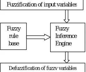
Fuzzy logic theory is adopted to speed control of the BLDC motor under disturbances condition which consists of the fuzzifier, fuzzy inference engine, fuzzy rule base and defuzzifier. Fuzzifier is used compares the speed error and change in speed error variables with predefined set of triangular membership functions into seven set of linguistic variables (Negative big, Negative medium, Negative small, Zero, Positive small, Positive medium, Positive big ). Membership functions of the inputs and output variables list below.
Fuzzy inference engine provides the link to the controller output from the input variables of the controller with help of fuzzy rule database mamdani model chosen for this proposed control system [4]
Fig. 2. FUZZY CONTROL SCHEME Fuzzification of input variables
Fuzzy rule base
Fuzzy Inference Engine
ISSN(Online): 2319-8753 ISSN (Print): 2347-6710
I
nternational
J
ournal of
I
nnovative
R
esearch in
S
cience,
E
ngineering and
T
echnology
(An ISO 3297: 2007 Certified Organization)
Website: www.ijirset.com
Vol. 6, Issue 6, June 2017
Fuzzy rule database are formed by the basis control strategy follows:
Fig. 3. Rule Viewer in Simulink Toolbox
Defuzzifier receives the output (linguistic variable) of inference engine which converts into the single crisp values that act as the control signal. The centriod method has been used.
Before the real time implementation, the BLDC Motor drive with Fuzzy logic controller is simulated to predict the performance of the drive. The proposed BLDC Motor drive simulation carried out in MATLAB/SIMULINK.
The simulation model consists of Three Phase BLDC Motor, three phase inverter, Hysteresis current controller, Fuzzy logic speed controller. The reference speed, motor parameters and Fuzzy logic rule and membership function are given as input and the model output are motor speed, torque, voltage and currents. For different operating conditions, input parameters are applied to the simulation model and the performance of drive system is verified.
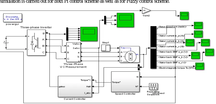
V. SIMULATION MODEL
The simulation model using PI and Fuzzy control scheme is shown in Fig. 4.
ISSN(Online): 2319-8753 ISSN (Print): 2347-6710
I
nternational
J
ournal of
I
nnovative
R
esearch in
S
cience,
E
ngineering and
T
echnology
(An ISO 3297: 2007 Certified Organization)
Website: www.ijirset.com
Vol. 6, Issue 6, June 2017
Simulation is carried out in MATLAB/SIMULINK environment. The simulation model contains the BLDC Motor, three phase Inverter, current controller and speed controller subsystems. Each subsystem has different components that perform a specific function. The various parameters of BLDC Motor are
No. of Phases = 3
Stator Phase resistance (Rs) = 3.07 Ω Stator Phase inductance (Ls) = 6.5 mH Moment of Inertia (J) = 0.014 Kg.m2 Viscous damping (F) = 0.0005 NMS
VI. RESULTS AND DISCUSSION
The response of the BLDC Motor Drive is simulated for various load torque values by keeping speed = 1000 rpm and reading are tabulated. The performance of the BLDC motor is tested for sudden change load at t=2 Sec. The Speed Output for the PI and Fuzzy Controller is given below for various torque values.
Fig. 5. PI controller Torque @ 1NM Fig. 6. PI controller Torque @ 2NM
Fig. 7. PI controller Torque @ 3NM Fig. 8. PI controller Torque @ 4NM
ISSN(Online): 2319-8753 ISSN (Print): 2347-6710
I
nternational
J
ournal of
I
nnovative
R
esearch in
S
cience,
E
ngineering and
T
echnology
(An ISO 3297: 2007 Certified Organization)
Website: www.ijirset.com
Vol. 6, Issue 6, June 2017
Fig. 11. Fuzzy controller torque 3NM Fig. 12. Fuzzy controller torque 4NM
The measured speed values are tabulated below:
S.No. Speed drop Restore time for speed
recovery Speed error
Torque
applied PI Controller
Fuzzy
Controller PI Controller
Fuzzy
Controller PI Controller
Fuzzy Controller
1Nm 965 998.2 0.6 0.02 5 0.7
2Nm 930 997.5 0.6 0.02 7 1.3
3Nm 900 996.5 0.6 0.023 12 1.9
4 NM 870 995 0.6 0.024 16 2.9
VII. CONCLUSION
The PI and fuzzy control techniques are successfully simulated for the BLDC motor drive system. The effect of Load disturbances variations on the performance of the BLDC motor drive system is investigated. The Simulation results are given in Table I shows that speed response of fuzzy controller-based BLDC motor drive is found to be better than the speed response of PI controller-based BLDC motor drive. The PI controller-based BLDC motor drive failed to provide improved performance under load variations of the system.
The results clearly show that fuzzy controller based BLDC motor drive can provide an improved speed response with consistently speed drop, restore time for speed recovery when the system is subjected to load disturbance in reference speed. Since the fuzzy control system is easy to design and implement, effective in dealing with the uncertainties and parameter variations, and has better overall performance, fuzzy controller-based BLDC servomotor drive system may be preferred over PI controller-based BLDC motor drive for automation, robotics and for many other applications.
REFERENCES
[1]R. Krishnan, Electrical Motor Drives – Modelling, Analysis and Control, Prentice Hall, 2001.
[2] Tan Chee Siong, Baharuddin, M.Fayzul, and M.Faridun N.T. “Implementation of Fuzzy Logic Controller for Permanent Magnet Brushless DC Motor Drives.” IEEE International Conference on Power and Energy, pp.462-467, 2010.
[3] Sudhanshu Mitra, R.SaidaNayak, and Ravi Prakash. “Modeling and Simulation of BLDC Motor using MATLAB/SIMULINK Environment.” International Research Journal of Engineering and Technology (IRJET), Vol 2, pp. 109-203, 2015.
[4] R. Arulmozhiyal, and R.Kandiban. “Design of Fuzzy PID Controller for Brushless DC Motor.” International Conference on Computer Communication and Informatics (ICCCI), Jan 2012.
ISSN(Online): 2319-8753 ISSN (Print): 2347-6710
I
nternational
J
ournal of
I
nnovative
R
esearch in
S
cience,
E
ngineering and
T
echnology
(An ISO 3297: 2007 Certified Organization)
Website: www.ijirset.com
Vol. 6, Issue 6, June 2017
BIOGRAPHY
Raja Sundramoorthy received the B.E degree in Instrumentation and Control Engineering from Anna University-Chennai, through Arulmigu Meenakshi College of Engineering, Kanchipuram, Tamil Nadu, India in 2006, the M.Tech in Embedded Systems and Technology from SRM University, Chennai, Tamil Nadu, India in 2012. He is currently pursuing his Ph.D degree in the Department of Electrical and Electronics Engineering, SCSVMV University, Kanchipuram, Tamil Nadu, India. He is having more than 10 years of teaching experience in the Department of Electrical and Electronics Engineering, SCSVMV University, Kanchipuram, Tamil Nadu, India. His research interest includes BLDC Motor Drives, FPGA based design, and Low power VLSI design.
Dr.M.Rathinakumar, born in Madurai, Tamilnadu, India, on July 19, 1969. He graduated from Thiyagarajar College of Engineering, affiliated to Madurai Kamaraj University under Electrical and Electronics Engineering in the year 1994. He obtained his post graduation in Power Systems from the same University in the year 1995. He obtained his Ph.D from SCSVMV University, Enathur, Kanchipuram, Tamilnadu, India in the year 2010. He has put around 25 years of experience in teaching Electrical Engineering. His areas of interest are Power systems, Power Quality, Power System Operation and Control. Presently he is working as Professor Department of Electrical and Electronics Engineering SCSVMV University, Enathur, Kanchipuram, Tamilnadu, India