Massive MIMO Performance over D-GOB, H-SUB
Beamforming Algorithms
1
Surendra Loya,
2Hari Praneet Sreenivasula,
3Harshni Vajrala,
4
Kavya Krishnavarapu,
5Rupa Sri Volupu
1,2,3,4,5Dept. of ECE, Usha Rama College of Engineering and Technology, Telaprolu,
Gannavaram, Andhra Pradesh, India
Abstract
Massive MIMO is to equip at base stations in wireless networks with large arrays of phase coherently co-operating antennas. The use of such arrays facilities spatial multiplexing of many User Equipment’s (UE’s) in the same time frequency resource and yields a coherent beamforming gain that translates directly in to reduced interference and improved cell edge coverage. Downlink beamforming in Massive MIMO either relies on Uplink pilot measurements the use of predetermined grid of beams with user equipment’s reporting their preferred beams mostly in frequency division duplexing operation. In this paper we observed the performance of various feedback based CSI beamforming algorithms based on MATLAB
Keywords
Massive MIMO, D-GOB, H-GOB, H-SUB, Beamforming algorithms
I. Introduction
Massive-multi input multi output (Massive-MIMO) is expected to be one of the essential technologies in meeting the diverse performance requirements of 5G, massive MIMO with hundreds of antennas is considered a key enabler for overcoming challenging propagation conditions. The performance gain of massive MIMO comes at the expense of increased system challenges including reference signal, channel quantization, channel state information feedback, beam steering and tracking, power consumption, beam failure detection and recovery, as well as hardware complexity. Mobile data traffic is increasing by leaps and bounds, driven by the development of new technologies, devices, applications and services. By 2021, growth of at least 10 times the traffic measured during 2015, which was higher than 5 exabytes (EB) per month, was expected to grow by 65% compared to that of 2014. [15] [16]
Today, GSM (Global System for Mobile Communications) and EDGE (Enhanced Data for Global Evolution) technologies dominate the worldwide subscriber market. At the end of the year 2015 reached a figure close to 7.4 billion subscriptions, of which 850 million correspond to users of LTE (Long-Term Evolution). However, considering the rapid rollout of the most advanced mobile telephone networks and the new needs of users, by 2021 an LTE domain with around 4.1 trillion subscriptions is expected, followed by WCDMA (Wide-band Code Division Multiple Access) and HSPA (High Speed Packet Access). In a smaller amount, there will be users of other technologies and 5G (5th Generation mobile networks), which would be launched this year reaching a number of subscriptions in the order of 150 million. The concept of cellular communication system emerged in the search for a solution to the problem of spectral congestion and capacity of users of the first wireless communication systems, in which there was a single high-power transmitter over the entire
coverage region. The idea was to divide the service area into small areas called cells, which are composed of a base station with a low power transmitter and operating with a portion of the available spectrum, increase the capacity of the system without incurring major technological changes [17].
The fifth generation of mobile telephony is the technological response to future challenges in terms of connectivity. In addition to offering improvements in mobile broadband services, such as high data rate, reliability and lower latency, its main objective is to support the complexity and high data demand resulting from integrating the Internet applications of objects (IoT, Internet of Things) to the network, without forgetting the commitment to maintain low energy consumption. This work focuses on the study and analysis of the performance of the most accepted beamforming techniques on the downlink of the Massive MIMO systems. Specifically, Digital beams (D-GOB), Hybrid Grid-of-beams (H-GOB) and Hybrid Subspace (H-SUB) are compared in terms of Sum rate, Spectral efficiency and SNR loss.
II. System Model
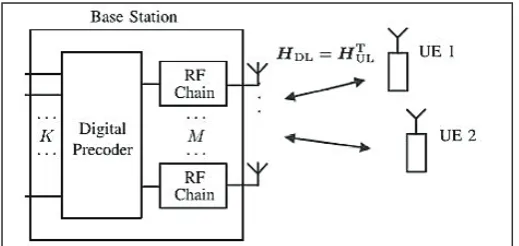
Consider the DL of the single call Massive MIMO system in which an M antenna BS communicates with K single antenna UE’s in the same frequency resource.
Fig. 1: System Model for Massive MIMO
M antennas can communicate over wireless channel with single antenna UE’s with OFDM with L sub-carriers.
Let
h l
k( )
CMX1 for k=1……. K and l=1…L it denotes channel vector between base station and kth UE at the lth subcarriers and let[
1]
( ) ( )... ( )k T
H l = h l h l (1)
Denotes KxM channel matrix. Input and output relation is
(2)
Where y(l) is the vector contains the received signal of
the UE’s, , signal-to-noise ratio (SNR), is
III. Beaforming Techniques for Massive Mimo
A. Digital Grid-of-beams(D-GOB)
Fig. 2: Digital Grid of Beams
Each UE individually reports the indices and complex gains of a number, N of beams and implement in digital domain. UE’s can independently select the beams and also reporting to the beams for each sub-carrier. Achievable sum rate can be determined by
average over all the sub-carrier. Denoted by . Complex
gain of UE’s is
( ) T ( )
k k
g l =C h l (3)
If it selects the N beams and forms Q lk
( )
. The UE reports for( )
k Q l is
( ) T( ) ( )
k k k
g l =B l h l (4)
Where MXN matrix,Bk l( ) is obtained from the relevant beams
which is extracting from ‘C’. In the same way, the BS can produce the N beams denotes by h lˆ ( )k
2
ˆ ( ) argmin
T( )
( )
k k k
h l
=
B l v g l
−
(5)In general, multi-user interference may occur in this D-GOB due to UE reported beamforms are different to each other i.e., Q li
( )
& Q lj
( )
. We are suppressing that interference between the users.So, that we are applying the ZF for the estimated channel matrix. [2] [3]
1
ˆ ˆ
ˆ ( ) ( )... ( )k T
H l = h l h l (6)
ZF precoding [4]
( )
( ) / ( )
k k l k
p l =z z l (7)
Received SINR by the Kth UE’s is
(8)
Achievable sum rate by using Shannon’s Hartley capacity
(9)
Precoding P l( ) are designed by according to the ZF principle. Precoding is impossible to completely suppress the interference until complete CSI obtained at the BS, unless N=min( , )M M′ .
B. Hybrid grid-of-beams(H-GOB)
Fig. 3: Hybrid Grid of Beams
UE’s sends individually reports to the BS and complex gains of N beams and it is also Beams can applied to across all subcarriers. It also enables the beamforming in the analog Hardware. It has one special case when N=1 and additionally one dispenses with all the digital signal processing.
Sometimes it is also called as a anlog-only beamforming. It can be used in the communications standards such as IEEE 802.11ad. [7]
In this H-G0B, The problem is beam selection and it can be optimizing by using
arg min
2
1
ˆ
1/
L k( )
k( )
l
L
h l h l
=
−
∑
(10)Qk
subject to Qk {1, . . . , M_}, |Qk| = N,
C. Hybrid Subspace (H-SUB)
Fig. 4: Hybrid Sub Space
In this H-SUB the BS can interacts with the all UE’s and decides the common set of N beams that are also for all the UE’s and the reports of UE’s are the complex gains of the N beam and it can implement in the analog domain then the same set of beams are must use for all UE’s.
Vector precoded transmit signal,
(11)
Here, the precoder is the frequency selective and B is not frequency selective.it can also realized by using an analog hardware (i.e., N phase shifters and N signal combiners) [5-6].
A typical certain structure is enforced on the matrix B to reduce the cost effective. Here B can be obtained from the code book matrix [5-6].
Optimal beam selection for H-SUB is
H-SUB (12)
IV. Result Analysis
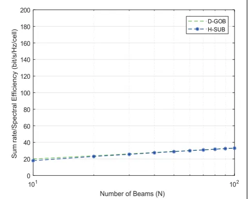
A. For Sum Rates or Spectral Efficiency
101 102
Number of Beams (N)
0 20 40 60 80 100 120 140 160 180 200 S um ra te /S pe ct ra l E ffi ci en cy (b it/ s/ H z/ ce ll) D-GOB H-SUB
Fig. 5. Scenario 1
No of UE’s (K)=2 and the sum rate or spectral efficiency of D-GOB, H-SUB at N=10 are 10 bits/sec/Hz and at the N=100 are 16.56 bits/sec/Hz respectively.
101 102
Number of Beams (N) 0 20 40 60 80 100 120 140 160 180 200 S um ra te /S pe ct ra l E ffi ci en cy (b it/ s/ H z/ ce ll) D-GOB H-SUB
Fig. 6: Scenario 2
No of UE’s (K)= 4 and sum rate or spectral efficiency of D-GOB, H-SUB at N=10 are 17.93, 17.62 bits/sec/Hz respectively and N=100 are 33.01, 33.21 bits/sec/Hz.
101 102
Number of Beams (N)
0 20 40 60 80 100 120 140 160 180 200 Su m ra te /S pe ct ra l E ffi ci en cy (b it/ s/ H z/ ce ll) D-GOB H-SUB
Fig. 7: Scenario 3
No of UE’s(K) = 8 and sum rate or spectral efficiency of D-GOB, H-SUB at N=10 are 39.71, 25.66 bits/sec/Hz respectively and at N=100 are 65.48, 65.48 bits/sec/Hz respectively
101 102
Number of Beams (N)
0 20 40 60 80 100 120 140 160 180 200 S um ra te /S pe ct ra l E ffi ci en cy (b it/ s/ H z/ ce ll) D-GOB H-SUB
Fig. 8: Scenario 4
No of UE’s (K) =16 and sum rate or spectral efficiency of D-GOB, H-SUB at N=10 are 79.55, 3.56 bits/sec/Hz respectively and at N=100 are132, 129 bits/sec/Hz respectively.
101 102
Number of Beams (N)
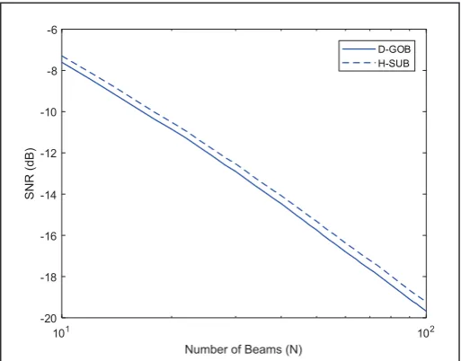
-16 -15 -14 -13 -12 -11 -10 -9 -8 -7 SN R (d B) D-GOB H-SUB
No. of UE’s (K)=2, The SNR loss of D-GOB and H-SUB at N=10 are -8.601, -7.31 dB respectively and at N=100 are
-15.51, -14.11db
101 102
Number of Beams (N)
-13 -12 -11 -10 -9 -8 -7 -6 -5
SN
R
(d
B)
D-GOB H-GOB
Fig. 10: Scenario 1 using MR Precoding Function
No. of UE’s (K)=2, The SNR loss of D-GOB and H-SUB at N=10 are -5.68, -5.33 dB respectively and at N=100 are -12.22, -11.72 dB
101 102
Number of Beams (N)
-35 -30 -25 -20 -15 -10
SN
R
(d
B)
D-GOB H-SUB
Fig. 11. Scenario 2 using ZF precodinhg function
No. of UE’s (K)=4, The SNR loss of D-GOB and H-SUB at N=10 are -16.71, -13.69 dB respectively and at N=100 are -31.33, -28.7 dB
101 102
Number of Beams (N)
-20 -18 -16 -14 -12 -10 -8 -6
SN
R
(d
B)
D-GOB H-SUB
Fig. 12: Scenario 2 using MR Precoding Function
No. of UE’s (K)=4, The SNR loss D-GOB and H-SUB at N=10 are -7.551, -7.234 dB respectively and at the N=100 are -19.54, -19.15 dB
101 102
Number of Beams (N) -65
-60 -55 -50 -45 -40 -35 -30 -25 -20 -15
SN
R
(d
B)
D-GOB H-SUB
Fig. 13. Scenario 3 using ZF precodinhg function
No. of UE’s (K)=8, The SNR loss of D-GOB and H-SUB at N=10 are -24.44, -18.57 dB respectively and at N=100 are -64.59, -57 dB respectively
101 102
Number of Beams (N) -35
-30 -25 -20 -15 -10 -5
SN
R
(d
B)
D-GOB H-SUB
Fig. 14. Scenario 3 using MR Precoding Function
No. of UE’s (K)=8, The SNR loss of D-GOB and H-SUB at N=10 are -9.01, -9.146 dB respectively and at N=100 are -30.27, 30.35 dB
V. Conclusion
By increasing the No. of UE’s in scenarios then the Sum rate (or) Spectral efficiency also increasing is to be observed from fig. 5,6,7,8 for the D-GOB, H-SUB, Observing the graphs, we identified that D-GOB is better. By increasing the No. of UE’s is scenarios by using ZF and MR precoding functions decreases the SNR loss
VI. Acknowledgment
References
[1] Jose Flordelis,Fredrik Rusek,Fredrik Tufvesson, Erik G. Larson, Ove Edfors,"Massive MIMO performance TDD versues FDD: What Do Measurements Say?”
[2] N. Jindal,“MIMO broadcast channels with finite-rate feedback,” IEEE Trans. Inf. Theory, Vol. 52, No. 11, pp. 5045–5060, Nov. 2005.
[3] N. Jindal,“MIMO broadcast channels with finite rate feedback,” in Proc. IEEE Global Telecommun. Conf. (GLOBECOM), Nov./Dec. 2005, pp. 1520–1524.
[4] A. Paulraj, R. Nabar, D. Gore,"Introduction to Space-Time Wireless Communications", 1st ed. Cambridge, U.K.: Cambridge Univ. Press, 2008.
[5] A. F. Molisch et al.,“Hybrid beamforming for massive MIMO: A survey,” IEEE Commun. Mag., Vol. 55, No. 9, pp. 134–141, Sep. 2017.
[6] R. W. Heath, Jr., N. González-Prelcic, S. Rangan, W. Roh, A. M. Sayeed,“An overview of signal processing techniques for millimeter wave MIMO systems,” IEEE J. Sel. Topics Signal Process., Vol. 10, No. 3, pp. 436–453, Apr. 2016. [7] Amendment 3: Enhancements for Very High Throughput in
the 60 GHz Band, IEEE 802.11 Working Group Standard, IEEE Standard 802.11ad, 2012.
[8] P. Harris et al.,“Performance characterization of a real-time massive MIMO system with LOS mobile channels”, IEEE J. Sel. Areas Communation. Vol. 35, No. 6, pp. 1244–1253, Jun. 2017.
[9] T. E. Bogale, L. B. Le, A. Haghighat, L. Vandendorpe, “On the number of RF chains and phase shifters, and scheduling design with hybrid analog–digital beamforming,” IEEE Trans. Wireless Commun., Vol. 15, No. 5, pp. 3311–3326, 2016.
[10] J. Vieira, F. Rusek, O. Edfors, S. Malkowsky, L. Liu, F. Tufvesson,“Reciprocity calibration for massive MIMO: Proposal, modeling, and validation,” IEEE Trans. Wireless Commun., Vol. 16, No. 5, pp. 3042–3056, May 2017. [11] T. L. Marzetta,“Noncooperative cellular wireless with
unlimited numbers of base station antennas,” IEEE Trans. Wireless Commun., Vol. 9, No. 11, pp. 3590–3600, Nov. 2010.
[12] T. L. Marzetta, E. G. Larsson, H. Yang, H. Q. Ngo, "Fundamentals of Massive MIMO", Cambridge, U.K.: Cambridge Univ. Press, 2016.
[13] T. L. Marzetta,“How much training is required for multiuser MIMO?” In Proc. 40th Conf. Signals, Syst. Comput. (ACSSC), Pacific Grove, CA, USA, Nov./Dec. 2006, pp. 359–363.
[14] F. Rusek et al.,“Scaling up MIMO: Opportunities and challenges with very large arrays,” IEEE Signal Process. Mag., Vol. 30, No. 1, pp. 40–60, Jan. 2013.
[15] X. Gao, O. Edfors, F. Rusek, F. Tufvesson,“Massive MIMO performance evaluation based on measured propagation data,” IEEE Trans. Wireless Commun., Vol. 14, No. 7, pp. 3899–3911, Jul. 2015.
[16] A Step Toward 5G in 2020: Low-cost OTA performance evaluation of massive MIMO base stations.
[17] A. Furuskar, S. Mazur, F. Muller, H. Olofsson,"EDGE: enhanced data rates for GSM and TDMA/136 evolution.”
Surendra loya received his B.Tech from JNTUH and M.Tech from Gitam UniversityVisakhapatnam.He is having 10 years teaching experience in variousengineering colleges and universitiesin the department of ECE.Presently he is working in ECE department Usha Rama college of Engineering and Technology.
Hari Praneet Sreenivasula received his degree on bachelor of technology in ECE in Usha Rama college of engineering and technology, Telaprolu, Andhra Pradesh affiliated to JNTUK Kakinada.
Harshinireddyvajarala received her degree on bachelor of technology in ECE in Usha Rama college of engineering and technology, Telaprolu, Andhra Pradesh affiliated to JNTUK Kakinada.
Kavya Krishnavarapu received her degree on bachelor of technology in ECE in Usha Rama college of engineering and technology, Telaprolu, Andhra Pradesh affiliated to JNTUK Kakinada.