Review Paper on Modified Rectangular Shaped
Microstrip Patch Antennas
1
Deepak Verma,
2Dheeraj Bhardwaj,
3Kanika Joshi,
4Komal Sharma
1Machine Vision Laboratory, Digital System Group, CSIR-CEERI Pilani, Rajasthan, India 2Dept. of Physics, Birla Institute of Technology, Mesra, Jaipur Campus, Rajasthan, India 3Dept. of Electronics & Communication, BIT-Mesra-Jaipur Campus, Jaipur, Rajasthan, India 4Swami Keshwanand Institute of Technology, Management & Gramothan, Jaipur, Rajasthan, India
Abstract
This paper presents review work on rectangular shaped microstrip patch antennas. In this paper four rectangular microstrip antennas have been studied and analyzed. We start our work with a reference rectangular patch which has six parallel slits of 5mmx37mm, and then we proceed with variation in length and width of those slits. We examine our results on two configurations, single layer and multilayer. With single layer rectangular microstrip patch antennas we obtained dual band broadband antenna which has a maximum bandwidth of 15.13% with a gain of 4.7dBi. Then we shifted our work on multilayer configuration. With multilayer configuration we obtained a multi frequency dual band broadband antenna (in comparison to single layer configuration) which have four resonant frequencies and have maximum bandwidths of 27.08% with a gain of 5.69dBi. All four antennas are simulated in IE3D simulation software, and all Antennas are designed on FR4 substrate.
Keywords
Rectangular Slot, Patch Antenna, Air Gap
I. Introduction
Now days the communication plays an excellent role in the worldwide society and almost all the communication systems are changing rapidly from wired to wireless. Wireless communication is much more flexible way of communication and antenna is the most important part of it. Recently the microstrip antenna is very useful due to its low cost, ease of Installation and integration with feed networks, low profile and small size [1-9]. On the move internet browsing, E banking, digital cable TV, etc. and small handheld devices, it is often required that the antenna to be achieved low profile good gain and wideband/multi-band characteristics. A number of approaches have been reported to obtain compact dual band micro-strip antenna such as loading of rectangular, circular and triangular patches by shorting pins, crossed slot and the use of a rectangular ring [2]. But the microstrip patch antenna has one serious drawback of narrow bandwidth as it limits the useful frequency band [2-3].
Review work is carried out in following steps: 1. Collection of Data.
2. Analyzed the Data.
3. Obtain Conclusion from collected Data.
In this paper data is collected from papers of international journal IJARCSSE, IJERSTE and from the papers of National and International conferences. All these papers are on rectangular shaped microstrip patch antennas. After data are collected, we reviewed each paper and then obtained conclusion. The Conclusion is obtained on the basis of Reflection coefficient graph, Bandwidth Plot, Smith chart and Gain v/s Frequency curve of respective antennas.
II. Geometries of Microstrip Antennas
In this paper, we proposed four antenna geometries, all are rectangular shaped with rectangular slits cut in it. First, we analyzed all these five geometries and then we discuss about their results.
A. Microstrip Antenna Geometry Patch 1
The overall dimension of patch 1 is 53mm x79mm as shown in fig. 1. This patch has six rectangular parallel slits cut parallel to each other in it. Dimension of all slits is equal and given as 37mm x 5mm.
Fig. 1: Patch 1
This patch is taken from the paper [5]. This patch is designed on FR4 substrate. Because of FR4 substrate is used, Z top is 1.6mm and dielectric constant is 4.4. FR4 is a lossy substrate and its loss tangent is given as 0.025. We took patch 1 as our reference patch. Simulation work is carried out using IE3D simulation software.
B. Microstrip Antenna Geometry Patch 2
The overall dimension of patch 2 is 53mm x 79mm as shown in fig. 2. This patch has six rectangular parallel slits cut in it. This patch was taken from the paper [6].
This patch is designed on FR4 substrate. Simulation work is carried out using IE3D simulation software.
C. Microstrip Antenna Geometry Patch 3
The overall dimension of patch 3 is equal to patch 1 and patch 2 that were 53mm x 79mm and it is shown in fig. 3.
This patch has six rectangular parallel slits, each of them has dimension of 37mm x 3mm. This patch is taken from the paper [7]. Simulation work is carried out using IE3D simulation software. In all patch antennas we used probe feed technique, reason behind that is impedance matching can be easily achieved with this feeding technique.
Fig. 3: Patch 3
D. Microstrip Antenna Geometry Patch 4
Patch 4 is a multilayer geometry. In this geometry we use two single layer microstrip antennas, one of which is our main patch and second is the substrate only. These two patches are placed with an air gap of 0.2 mm between them.
Fig. 4(a): Patch 4
Fig. 4(b): Side view of Antenna with Airgap
Only substrate is placed first then over substrate we produce an airgap of 0.2 mm and over this airgap we placed our main patch. This arrangement is shown in fig. 5. Main patch contains six rectangular parallel slits, dimension of which is 37mm x 3mm.
This patch is taken from the paper [8]. Simulation work is carried out using IE3D simulation software.
III. Result Analysis and Discussion
In this paper we presented review work of five microstrip patch antennas. Out of five microstrip antennas four antennas are on single layer configuration and one is on multilayer configuration. The result analysis is done on the basis of Reflection coefficient graph, Bandwidth, Smith Chart and Gain vs Frequency curve of each antenna. We took each geometry one by one and analyzed it.
A. Result Analysis of Patch 1
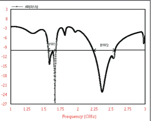
Reflection coefficient curve for patch 1 is shown in fig 5. From reflection coefficient we observe that patch 1 is resonant at two frequencies 1.65GHz and at 2.30GHz with respective bandwidths of 6.76% and 12.5%.
Fig. 5: Reflection Coefficient Curve for Patch 1
Impedance matching at both resonant frequencies is nearby 50, 0 ohm. Peak gain achieved with this antenna is 6dBi.
B. Result Analysis of Patch 2
Reflection coefficient curve for patch 2 is shown in fig. 6. Patch 2 is a modified form of patch 1, in which we modified length and width of all slits.
Fig. 6: Reflection Coefficient Curve for Patch 2
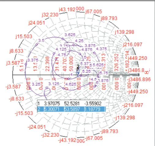
Fig. 7: Smith Chart for Patch 2
The value of impedance at both frequencies is 52.85, 3.4ohm and 53.62, 1.44ohm, hence patch 2 is well matched microstrip patch antenna.
Fig. 8: Gain Curve for Patch 2
Gain at both resonant frequencies is obtained from Gain curve which is shown in fig 8. Gain at both frequencies is 4.15dBi and 3.39dBi.
C. Result Analysis of Patch 3
In patch 3, we modify patch 1 in terms of width only; i.e. width of all slits is 3mm instead of 5mm. Reflection coefficient curve for patch 3 is shown in fig. 9.
Fig. 9: Reflection Coefficient Curve for Patch 3
From reflection coefficient we observe that patch 3 is resonant at two frequencies 2.68GHz and at 4.87GHz with respective bandwidths of 10.79% and 15.13%, since both bands are broadband we can say that designed patch is dual band broadband patch.
Fig. 10: Smith Chart for Patch 3
Value of impedance obtained from smith chart shown in fig. 10 is 44.7, 7.73ohm and 52.12, 0.42ohm. Gain at both resonant frequencies is 1.93dBi and 3.82dBi, as shown in gain curve in fig. 11.
Fig. 11: Gain Curve for Patch 3
Now in next analysis we examine a multilayer rectangular shaped patch with airgap.
D. Result Analysis of Patch 4
Patch 4 is a multilayer extension of patch 3. Airgap between two layers is equal to 0.2mm.
Reflection coefficient for patch 5 is shown in fig. 12.
From reflection coefficient we observe that this patch is resonant at four frequencies 4.52GHz, 5.67GHz, 6.17GHz and at 6.72GHz. Patch 5 has two broad bands one is 17.61% (4.52GHz and 5.67GHz) and second is 27.08% (6.17GHz and 6.72GHz). Hence we can say that patch 5 is a multi frequency dual band broadband microstrip antenna.
Fig. 13: Gain Curve for Patch 4
Gain at all Resonant frequencies obtained by fig. 13 (gain curve). At 4.52GHz, gain is 5.69dBi, at 5.67GHz 4.12dBi, at 6.17GHz, 3.29dBi and at 6.72GHz gain is 3.70dBi.
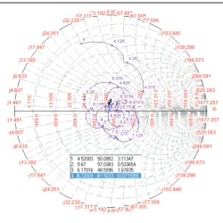
Fig. 14: Smith chart for Patch 4
Impedance matching at all Resonant frequencies is also ideal, according to smith chart in fig 14 values of impedance are 50.09, 3.11ohm, 57.03, 0.53ohm, 48.50, 1.67ohm and 47.92, -0.07ohm.
IV. Conclusion
In this paper, we examine five microstrip patch antennas with single layer and multilayer configuration. We start our work with reference patch 1, which have a maximum bandwidth of 12.5% with dual band performance and have a peak gain of 6dBi. Then we modified it in terms of length and width of the slits and obtained more and more enhanced results. For single layer configuration maximum achieved bandwidth is 15.13% on patch 3 with a dual band broadband performance and have a maximum gain of 4.7dBi.
At multilayer configuration maximum achieved bandwidth is 27.08% with multi resonant dual band broadband performance with a maximum gain of 5.69dBi.
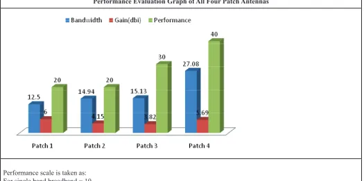
Considering antenna parameters graph, we conclude that microstrip antenna patch 4 is more appropriate in comparison to remaining antennas.
References
[1] Compact and Broadband Microstrip Antennas. Kin-Lu Wong Copyright © 2002 John Wiley & Sons, Inc. ISBNs: 0-471-41717-3 (Hardback); 0-471-22111-2 (Electronic).
[2] Zakir Ali, Vinod Kumar Singh, Ashutosh Kumar, Ayub Shahanaz,“E shaped Microstrip Antenna on Rogers Substrate for WLAN applications”, Proc. IEEE, pp. 342- 345, Oct. 2011.
[3] A.M. Hadian, H.R. Hassani,“Wideband Rectangular Microstrip Patch Antenna with U-Slot”, IEEE, Electronics Letters, Vol. 33, No. 25, April. 2009.
[4] Rahul S Batra, Dipika S Sagne,P.L. Zade,“Design and Analysis of Modified H Shaped Antenna for Wireless Communication", Advance Computing Conference (IACC Ghaziabad), IEEE 3rd International Conference, pp. 421 – 426, 22-23 Feb. 2013.
[5] Mayank Dwivedi, Mandeep Singh, Vinod Kumar, “Compact Dual Band Slotted Antenna for IEEE 802.11b Applications”, International Journal of Advanced Research in Computer Science and Software Engineering,
[6] Dheeraj Bhardwaj, Deepak Verma, Komal Sharma “Design of Modified Broadband Microstrip Rectangular Shaped Slotted Antenna for WLAN Application” National conference ECTME 2014, Vol. 3, pp. 44, January 2014.
[7] Deepak Verma, Dheeraj Bhardwaj, Komal Sharma “Design of Modified Rectangular Shaped Slotted Antenna for Wireless Applications” 2014 International Conference IAET 2014. [8] Deepak Verma, Dheeraj Bhardwaj, Komal Sharma “Design
of Dual Band Broadband Modified Rectangular Microstrip Patch Antenna with Airgap for Wireless Application”, International Journal of Enhanced Research in Science technology and Engineering, Vol. 3, Issue 2, pp. 331-339. [9] M. Venkata Narayana, I.Govadhani, K.P.Sai Kumar, K.
Pushpa Rupavathi published paper on “Comparative Analysis of Exponentially Shaped Microstrip-Fed Planar Monopole Antenna With and Without Notch”, Vol. 2, No. 11, October 2011. Journal of Emerging Trends in Computing and Information Sciences.
[10] M. Venkata Narayana, A.Vikranth, I. Govardhani, Sd. Khaja Nizamuddin, Ch. Venkatesh published paper on,“A Novel Design of a Microstrip Patch Antenna with an EndFire Radiation for SAR Applications”, Vol. 2, No. 1, January 2012. International Journal of Science and Technology. [11] I.Govardhani, M.Venkata Narayana, Prof S.Venkateswarlu,
K.Rajkamal Published paper in International Journal of Engineering Research and Applications (IJERA).
[12] Rashmi Sharma, Kirti Vyas, “A Novel Compact Monopole Antenna for C-band/Wi-Fi/IEEE 802.16 Systems”, IJSCE, November 2012.
[14] K.P. Ray, Girish Kumar,“Compact and Broadband Microstrip Antennas” 2003 Artech house Inc.
[15] [Online] Available: http:en.wiki .edia.org/wiki/WiMAX/ Wlan.
[16] Gagandeep Kaur, Geetanjali Singla, Simarjit Kaur, “Design of Wideband Microstrip Patch Antenna Using Defected Ground Structure for Wireless Applications”, International Journal of Advanced Research in Computer Science and
Software Engineering, Vol. 3, Issue 10, October 2013. [17] L. H. Weng, Y. C. Guo, X W. Shi, X. Q. Chen,“An Overview
On Defected Ground Structure”, Progress In Electromagnetics Research B, Vol. 7, pp. 173–189, 2008.
[18] Ashwini K. Arya, M.V.Kartikeyan, A.Patnaik,“Defected Ground Structure in the perspective of Microstrip Antennas: A Review”, Frequenz, Vol. 64, pp. 79–84, 2010.
Table 1: Concluding Table
Patch no. Geometry Resonant Freq. (GHz) Bandwidth (%) Gain(dBi) Performance
1 1.65GHz2.30GHz 6.76%12.5% 6dBi Dual Band
2 3.97GHz5.30GHz 14.94%3.53% 4.15dBi3.34dBi Dual Band
3 2.68GHz4.87GHz 10.79%15.13% 1.93dBi3.82dBi BroadbandDual Band
4
4.52GHz
5.67GHz 17.61% 5.69dBi4.12dBi
Multi Resonant Dual Band Broadband 6.17GHz
6.72GHz 27.08% 3.26dBi3.70dBi
Graph:
Performance Evaluation Graph of All Four Patch Antennas
Performance scale is taken as: For single band broadband = 10
Dual band = 20
Dual band & broad band = 30
Multi resonant, dual band & broad band = 40
Application of Different Patches
Patch no. Applications
Patch 1 WLAN and Wi-Max
Patch 2 C Band
Patch 3 S Band and C Band
Patch 4 Wi-Max
Patch 5 WLAN Band, IMT Band, Wi-Max and C Band
Mr. Deepak Verma received the B.E. degree in Electronics and Communication from the Birla Institute of Technology, Mesra Jaipur Campus in 2014. Currently, he is Project Fellow in machine vision lab of digital system group at CEERI Pilani. He has published more than Eight Research Papers in the reputed International Journals, National Journals and Conferences. His research interests include wireless communication, specifically microwave comm. and microstrip antennas. Along with these he also likes to work with computer networks, protocols and network devices like router and switches.
Dr. Dheeraj Bhardwaj received the Ph.D. degree in the field of Microstrip Patch Antennas from the University of Rajasthan, Jaipur, in 2011. Currently, he is an Assistant Professor of the Department of Physics at Birla Institute of Technology, Mesra, Jaipur Campus. He has published more than Sixty Research Papers in the reputed International Journals, National Journals and Conferences. He has guided more than Twenty final year research projects of B.E., M.Sc. and M.Tec. Students. His research interests include Microstrip antenna for modern wireless communication, Space Communications and Satellite Navigation.
Dr. Komal Sharma received the Ph.D. degree in the field of Microstrip Antenna from the University of Rajasthan, Jaipur, in 2012. Currently, she is a Reader of the Department of Physics at Swami Keshvanand Institute of Technology Management & Gramothan, Jaipur. She has been working on the design and development of microstrip patch antenna of various shapes and has published more than Thirty Five Research Papers in the reputed International Journals, national journals and Conferences. Her research interest includes Microstrip antenna for wireless communication for various applications.
![fig. 2. This patch has six rectangular parallel slits cut in it. The overall dimension of patch 2 is 53mm x 79mm as shown in This patch was taken from the paper [6]](https://thumb-us.123doks.com/thumbv2/123dok_us/1337487.1642300/1.595.305.437.604.782/rectangular-parallel-slits-overall-dimension-patch-shown-paper.webp)