Detecting Design Patterns in Object-Oriented
Program Source Code by Using Graph
Matching Algorithm
Ghanshyam Yadav1, Anil Kumar Pandey2 and Ravi Shankar Shukla3
I. INTRODUCTION
A design pattern that is general reusable resolution to a normally occurring issue in software system design. It is outlined as or model for the way to resolve an issue that may be utilized in many various conditions. There present three main kinds of design patterns that is architectural patterns, Gang of four (GoF) design patterns and idiom patterns. During this paper we have a tendency to focus within the GoF design patterns that is cataloged within the wide documented book by the “Gang of Four” [1]. The authors classified twenty three patterns consistent with the aim and consistent with the scope. The aim reflects what a pattern does: patterns will have creational, structural, or behavioural purpose. The scope classification specifies whether or not the pattern applies primarily to categories or to things. While other authors recommend that design patterns give easier maintainability and reusability, a lot of apprehensible implementation and a lot of versatile design. In recent years, several researchers have tried to gauge the impact of GoF design patterns on software system maintainability, they conducted many empirical strategies such case studies, surveys and experiments, however safe conclusions can not be drawn since the results cause totally different directions. A design pattern has to be investigated before it's used and therefore the designers expected to own an honest understanding and knowledge with design patterns. at this condition, some issue still face the practiced designer that is time intense to understanding, identification and investigation of the design pattern acceptable to his applications.
Graph based mostly approached are used in several software system engineering issues. Many algorithms are projected for design patterns detection like as [2, 3, 4]. Like these similar works on design pattern detection are mentioned in section II name as related work. This paper presents a design pattern detection technique by graph matching algorithm. Here, the graphs are admire the connection graphs that exist within the UML diagrams of system design (model graph) as well as in UML diagrams of design patterns. within the classic idea of actual graph
matching, the aim is to see whether or not two graphs are identical or whether or not a subgraph of 1 exists within the other graph.
1
Department of Computer Science and Engineering Invertis Institute of Engineering and Technology Bareilly, U.P., India
2
Department of Computer Science and Engineering Invertis Institute of Engineering and Technology Bareilly, U.P., India
3
Department of Computer Science and Engineering Invertis Institute of Engineering and Technology Bareilly, U.P., India
e-ISSN:2278-621X
Abstract- Design Patterns are solution to common continual design issues. Design Pattern Detection is most significant
activity that will support lots of re-engineering method and so provides significant info to the designer. Information of design pattern exists within the system design improves the program understanding and software system maintenance. Therefore, an automatic and reliable design pattern discovery is needed. Graph theoretical approaches had been used for design pattern detection in past. Here we tends to applying the algorithm that relies on the graph matching. A similar algorithm we tends to using here for design pattern detection from the system design.
The algorithm relies on the one-one correspondence from nodes of the system design graph (model graph MG or SG system Graph) to design pattern graphs (DPG) technique. Any two graph are told to match when there's a one-one correspondence from DPG to MG. The define of this paper is as follows. In section II is related works mentioned. Section III explains the our proposed work in which firstly we define graphical representation of model graph and design patterns in terms of relationship graphs is explained. In the second part the graph matching algorithm is defined. In section IV the design pattern detection is defined with use of some examples. finally we conclude our work in section V.
II. RELATED WORK
There is many approaches regarding to the Design Pattern Detection in the Object-Oriented Program Source code. The first try for automatic detection design pattern was by Brown [5]. during this work, Smalltalk code was reverse-engineered to facilitate the detection of 4 well-known patterns from the catalog by Gamma et al. [1]. Antoniol et al. [4] developed a method to spot structural patterns within a system to watch, however helpful a design pattern recovery tool might be in program maintenance and understanding. The Nikolaos Tsantalis [6] projected a technique for design pattern detection with use of similarity scoring technique. However, the limitation of similarity algorithm is that it calculates the similarity between two nodes, not the similarity between two graphs. Jing Dong [2] gave another approach known as templet matching, that calculates the similarity between sub graphs of two graphs rather than vertices, to resolve the upper limitation. S. Wenzel [3] purposed a distinction calculation technique works on UML models. The advantage of distinction calculation technique on different style pattern detective work technique is that it detects incomplete pattern instances additionally. Bergenti and Poggi [6] developed a technique that examines UML diagrams and proposes the software system designer modifications to the patterns that result in design patterns. Kim et al. Champin et al. [7] projected a replacement technique to recover the GoF[1] patterns that use software system measuring skills. They developed a design pattern CASE tool to facilitate the simple application of their technique. DPR technique used the three types of product metrics, and also the measuring planned was established on the idea of the GQM paradigm. several different tools are developed for design pattern detection. But there's no normal tool for it that may be helpfull to solve the maintainer‟s issue or problem. Stencel and Wegrzynowicz, [8] projected a technique for automatic design pattern detection that's ready to detect several nonstandard implementation variants of design pattern. Their technique was customizable as a result of a replacement pattern retrieval question is introduced together with modifying existing one and so repeat the detection with use of the results of earlier ASCII text file analysis keep during a computer database. Disadvantage of this was that the strategy wasn't general enough to spot all design patterns. Additional the interpretation of initial order logic formulae as SQL queries is extremely effortful and fallible.
For the detection of the design patterns, Gupta et al. [9] used the Normalized cross correlation (NCC). They started by writing the relationship matrices of the link graphs that extracted from the UML diagram of the system design and also the design pattern. Then, they apply the NCC to find the degree of similarity between the two graphs (one for the system design and also the different for the design pattern) for the aim of detect the Design patterns. The disadvantage of this technique is, it's time intense to calculate every relationship matrix clearly. Gupta et al [10] projected a graph matching rule supported the A* rule. The proposed rule divided the matching method, 1) between the design pattern graph (DPG) and also the model graph (MG), 2) between the design pattern graph (DPG) and also the system model graph (SG), into K phases. The value of K is counting on the minimum variety of nodes (M) within the 2 graphs utilized in matching. It is selected from the values between one to M. the matter with this technique, it's effective within the case of little amounts of K values.
Pande et al[11] projected a replacement matching rule that extracts the relationship of directed graphs from the UML diagram of system software model and design patterns. Then after that they attempt to find the existence of the design patterns within the model graph that used Depth-Node-Input Table (DNIT). DNIT arranges the varied model graph relationships and also the design pattern by depth. This method is time intense within the method of making the DNIT entities for the model graph and for all design patterns graphs. Another approach used the idea of the boolean operate to discover the patterns. Gupta et al. [12] Offering a replacement technique that discover pattern depend upon the boolean function. They remodel the UML diagrams of the model graph and also the design pattern into boolean function with SOP type. Then, they find the existence of the design patterns by comparison the 2 boolean functions. The drawbacks of this technique is that it not considers the detection of design patterns that have relationship from a node to itself like the singleton design pattern. Some approaches determine the quantity of design pattern instances within the system. Pande et al. [13] attempted to notice the design patterns and its instances by first, construct decision tree with help of rowcolumn elements for all potential subgraphs adjacency matrices of the system graph. After that, find the
row-column components of the design pattern adjacency matrix. Then, check the isomorphic by traverse the decision tree to discover
system under study. It is time consuming once discover the matches for every relation separately. Yu et al [16] discover the design patterns by graph similarity between system design and also the design pattern graph. They begin by distinguishing all the candidate nodes from system graph that correspond to design pattern nodes then, choose a number of them to make sub-graphs of system graph. Finally, they notice the isomorphic between design pattern and them. This technique discovers what quantity instance of the design pattern within the system graph. This method represents the link between categories within the UML diagram of system software model by distribution the weight to edges within graph illustration, this weight describe all the link between tow vertices. So, in the big systems, it shall be time intense to spot the link for every edge and after that calculate its weight.
III. PROPOSED WORK
A. Representaion of System Graph with Relation Graph:-
The system under the study or the system that we got the source code is taken initial, the corresponding the category diagram of UML of that code (object orientating system) is drawn. subsequently the link graphs (that exists in UML diagram) is extracted. we had taken the UML Diagram of system designs shown in Figure one. There is 3 relationships (i.e. generalization, direct association and the aggregation), the corresponding relationship graph (i.e. directed graph) is shown in Figure two. The Generalization relationship graph has the relationship between the four of the nodes, the Direct Association relationship graph has relationship between 3 of the nodes and the Dependency relationship between 2 of the nodes.
Figure 1. UML Diagram of system design [17]
i. Generalization Graph ii. Direct Association Graph iii. Dependency Graph
Figure 2. Corresponding Relationship Graphs for UML diagram of Fig. 1
B. Proposed Algorithm –
Let us take into account a directed graph G (V, E), wherever V may be a set of the vertices (nodes) and E may be a set of the edges [20]. To compare any two graphs it should be necessary to spot corresponding vertices. The correspondences between the two nodes a one to one correspondence [20]. We take into account 2 graphs, G1 (V1, E1) and G2 (V2, E2), and the matrix show the correspondences between the V1 and V2. Here V1and V2 denote the sets of the vertices, in graph G1 and G2 relatively, equally E1 and E2 is the set of edges in graph G1 and G2 relatively.
of the nodes of DPG have one to one correspondence in SG and a few of the nodes of DPG (design pattern graph) have not one to one correspondence then it shall be partial matching, and if none of the nodes of DPG have one-one correspondence to nodes of SG then it shall be not matching.
IV. EXPERIMENT AND RESULT
There is twenty three GoF (Gang of Four) [1] design patterns. UML diagrams may be drawn for every of the corresponding design patterns. Here we tends to considering a number of them.
All these cases will be represented well with the help of examples.
A. Detection of Strategy Design Pattern: Complete Matching:-
Firstly, we tends to considering the factory Pattern, the UML case diagram and corresponding relationship graph (DPG) is shown in Fig. 3 and Fig. four relatively. The factory pattern has just one relationship as direct association and its corresponding graph is shown in fig four. Currently we are able to build a correspondence between the nodes of fig four and fig (2.ii). There be a mapping between node "1" and node "a" i.e. [1,a], and the mapping between node "2" to "b" i.e. [2,b] and node "2" to node "c" i.e. [2,c]. we are able to represent these mapping by a matrix during which the (i,j)th entry are zero if there is present a correspondence from any node "i" belong to the design pattern graph to a node "j" belong to system model graph. The correspondence between fig four to fig (2.ii) is shown in Table I . Here every node of fig four contains a one to one correspondence in fig (2.ii) thus there present be a complete matching.
a b c d e f g
1 0
2 0 0
Fig 3. Factory Design Pattern [17] Fig 4. Direct Association Graph of Fig. 3. Table 1 . Direct association one- one matrix
B. Detection of Command design Pattern: Partially Matched:-
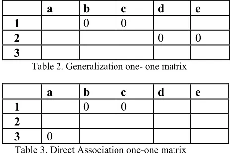
In some cases there is additionally condition that a specific design pattern partly exist within the system model (case ii discussed in section 4). For instance think about the mediator pattern, the UML case diagram and corresponding relationship graph is shown in Fig. 5 and Fig. six relatively. During this case we shall not notice the complete matching. Here within the generalization one to one relationship matrix (Table II) the nodes "1" and "2" have the one to one mapping, however the node "3" don’t have any one to one mapping. thus it’s a partial matching. Equally we will see that in the direct association one to one matrix (Table III) where all the nodes except node 3 have one to one mapping, however the node "3" have not any mapping, thus there partial matching found.
a
b
c
d
e
1
0
0
2
0
0
3
Table 2. Generalization one- one matrix
a
b
c
d
e
1
0
0
2
3
0
Table 3. Direct Association one-one matrix
C. Specific design pattern might not exist:-
Above as we had seen the design pattern existence (complete or partially) however it may be happen that a particular design pattern not exist within the model graph. During this case we are going to not detect any matching between relationship matrices. For instance if we have a tendency to take singleton design pattern as (Fig. 7), where only 1 relationship: direct association on itself node. Corresponding DPG is shown in Fig. eight and its Direct Association one -one matrix shown in Table IV. Here is no anyone to one correspondence from node "1" to any of the nodes belong in model graph nodes. So matching can not be found.
a
b
c
d
e
1
Fig.7 Singleton Design pattern [17] Fig 8. Graph for fig 11 Table 4. Direct Association one -one matrix
V. CONCLUSION AND FUTURE WORK
This paper proposed the approach for design pattern detection with the help of Graph matching algorithm technique. We tends to took the connection graphs of the system model graph (SG) and a design pattern graph(DPG), then the mapping relationship one to one correspondence matrices created and tried to search out whether or not all of the nodes of design pattern graph (DPG) have a one to one correspondence to the nodes of system model graph (MG). If all of the nodes of design pattern graph (DPG) have a one to one to one mapping into model graph (MG), we are saying that the design pattern exist within the system model graph. If a number of the nodes of design pattern graph (DPG) have one to one correspondence and a few of the nodes don’t have one to one correspondence, design pattern partly exist within the model graph, and if none of the nodes of design pattern graph (DPG) have one-one mapping to nodes of system model graph (MG), design pattern not exist within the model graph.
REFERENCES
[1] Gamma, E., Helm, R., Johnson, R., Vlissides, J.: Design Patterns Elements of Reusable Object-Oriented Software. Addison- Wesley, Reading
(1995).
[2] Dong J., Sun Y., Zhao Y., “Design Pattern Detection by Template Matching”, the Proceedings of The 23rd Annual ACM Symposium on
Applied Computing (SAC), pages 765-769, Ceará, Brazil, 2008.
[3] Wenzel S., Kelter U., “Model-driven design pattern Detection using difference calculation”, In Proc. of the 1st International Workshop on
Pattern Detection for Reverse Engineering (DPD4RE), Benevento, Italy, 2006.
[4] Antoniol G., Casazza G., Di Penta M., Fiutem R., “Object-Oriented Design Patterns Recovery”, J. Systems and Software, vol. 59, no. 2, pp.
181-196, 2001
[5] Brown, K.: Design Reverse-Engineering and Automated Design Pattern in Smalltalk.Technical Report TR-96-07, Dept. of Computer Science,
North Carolina State Univ.(1996).
[6] Bergenti, F., Poggi, A.: Improving UML Designs Using Automatic Design Pattern Detection. Kundur D., Hatzinakos D., Towards robust logo
watermarking using multiresolution image fusion, IEEE Transcations on Multimedia 6 (2004) 185-197.
[7] Champin P. A., Solnon C., “Measuring the similarity of labeled graphs”, 5th International Conference on Case-Based Reasoning (ICCBR),
Lecture Notes in computer Science- Springer Verlag, 2003. L. Ghouti, A. Bouridane, M.K. Ibrahim, and S. Boussakta, “Digital image
watermarking using balanced multiwavelets”, IEEE Trans. Signal Process., 2006, Vol. 54, No. 4, pp. 1519-1536.
[8] Stencel K. and Wegrzynowicz P., “Detection of Diverse Design Pattern Variants”, 15th Asia-Pacific Software Engineering Conference, IEEE
Computer Society, 2008.
[9] M. Gupta, A. Pande, R. Singh Rao, and A.K Tripathi, "Design Pattern Detection by normalized cross correlation," in Proc. IEEE International
Conference on Methods and Models in Computer Science (ICM2CS), India, 2010, pp. 81-84.
[10] M. Gupta, R. Singh Rao and A.K. Tripathi, "Design Pattern Detection using inexact graph matching," in Proc. IEEE International Conference
on Communication and Computational Intelligence (INCOCCI) , India, 2010, pp.211-217..
[11] A. Pande, M. Gupta and A.K. Tripathi, "DNIT — A new approach for design pattern detection," in Proc. IEEE International Conference on
Computer and Communication Technology (ICCCT),
[12] A. Pande, M. Gupta and A.K. Tripathi ,"Design pattern mining for GIS application using graph matching techniques," in Proc. 3rd IEEE
International Conference on Computer Science and Information Technology (ICCSIT), India, 2010, pp.477-482.
[13] A. Pande, M. Gupta and A.K. Tripathi, " A Decision Tree Approach for Design Patterns Detection by Subgraph Isomorphism”, in Proc.
International Conference ICT 2010, India, 2010, pp. 561-564.
[14] M. Gupta, R. Singh Rao, A. Pande and A.K. Tripathi,” Design Pattern Mining Using State Space Representation of Graph Matching”, in
Proc. 1st International Conference on Computer Science and Information Technology CCSIT, India, 2011, pp. 318-328.
[15] M. Gupta and A. Pande,” Design Patterns Mining using Subgraph Isomorphism: Relational View”, International Journal of Software
Engineering and Its Applications, vol. 5, pp. 47-56, Apr. 2011
[16] Y. Dongjin; J. Ge; W. Wu, "Detection of design pattern instances based on graph isomorphism," in Proc. 4th IEEE International Conference on
Software Engineering and Service Science (ICSESS), China, 2013 , pp.874-877.
![Figure 1. UML Diagram of system design [17]](https://thumb-us.123doks.com/thumbv2/123dok_us/1404255.1652641/3.612.103.497.305.581/figure-uml-diagram-of-system-design.webp)
![Fig 5.Mediator Design Pattern [17] i. Generalization Graph ii. Direct Association Graph Fig](https://thumb-us.123doks.com/thumbv2/123dok_us/1404255.1652641/4.612.84.530.606.712/mediator-design-pattern-generalization-graph-direct-association-graph.webp)