OPTIMIZING THE PERFORMANCE OF UNCOATED AND
MULTILAYER COATED CERMET INSERTS FOR SURFACE
ROUGHNESS OF EN-8 STEEL
Manpreet Singh1, Amandeep Singh bansal2, & Manpreet Singh3
1. INTRODUCTION
In modern civilization, the manufacturing of every product involved the metal cutting process. In metal cutting process, cutting tools is one of the vital elements to be considered. Research is being carried out by the manufacturers to decrease the cutting cost and increase the quality of machined parts. The main objective of the machining is to produce a high quality product at minimum cost. To meet the increasing demands and to improve the overall production the manufacturing industry is working on the development of materials of cutting tools. It will reduce the manufacturing cost and lead time, improve surface roughness and achieve high cutting temp and its detrimental effects can be reduced by using heat and wear resistant cutting tool material like carbide, cermet, ceramic and coated tools.
Existing tool materials can be improved by using various types of coating materials. By doing coating on the tools, machining become easy as they offer greater wear resistance and deformation under high speed machining. In 1969 introduced the first coated cemented carbide index able inserts for turning (Soderberg et al. 2001).. Hard substances like TiN TiC and Al2o3 are also used for coating as they improve the cutting tool capabilities. AS a result, the tools can cut at higher speed with reduced power consumptions(Watmon et al. 2010).The cemented carbide tools which is coated with TiC, TiN having lifetime ten time more than uncoated tools (Schulz et al. 2003).
For the cutting tools one of the crucial parameter is hard coating. Hard coatings are present is the frone of thein films having thickness from few nanometers to few millimeters and the number could vary from one layer to hundred of layers. The life of tool can be enhanced with the help of hard coatings. If we compare the tool lye of tincoated tool and un coated HSS tool then it has been observed that tool lye of tin coated tool is four times than that of second one(Arshi et al. 2013).
One of the important process for the protection of environment is the process of dry turning which due to its reduced overhead cost is become popular these days. It is also called as green machining in the contest of environment perceptive (Klocke et al. 1997).. Brittleness of the tools can be enhanced with the presence of cutting fluid which minimizes the problem of thermal shock in a interrupted cutting environment (Haron et al. 2006). METAL
1.1 Cutting Tool Types
The process of metal cutting can be defined as the metal removal from work piece which usually accurse in the form of chips for obtaining finished product along with the desired characteristics like size and shape. For improving the quality and
production rate the operating conditions can be varied to a greater extent in context with the reduced cost. Due to the economic competition in current machining world a lot of research work is done continuously for the better quality and enhanced cutting tool materials resulting in the increased productivity. High weight and strongness are two important parameters kept into mind for the manufacturing of new products resulting in the requirement of more efficient tool materials which is the main reason for continuous research in this area.
1 Department of Mechanical Engineering, CTIEMT, Jalandhar, Punjab, India 2 Department of Mechanical Engineering, CTIEMT, Jalandhar, Punjab, India 3 Department of Mechanical Engineering, SSIET, Jalandhar, Punjab, India
Vol.(9)Issue(1), pp.148-157
DOI: http://dx.doi.org/10.21172/1.91.23
e-ISSN:2278-621X
2. Ceramics
3. Cemented Carbides 4. Cermets
5. Cubic Boron Nitride (CBN) 6. Diamond
7. Coated Carbides
Cermet materials are known for having high hardness and toughness. These were first introduced in 1960. These are composite materials made from ceramic materials and metals which results in high temperature resistance due to ceramic material and high flexibility and electrical conductivity because of metals. Furthermore, cermets are composed of nitrides and carbides.
1.2. Coatings
Coatings are the Circulation block (boundary) as they can intercept the direct relation between chip formed & the cutting substance itself. The mixture used in making the coating are very rigid & high friction resistance. Typical elements used in coating are titanium carbide, Titanium nitride , Titanium carbonit ride& alumina. All there elements are less mix in iron . Types of Coating
Single layer coatings Multi-layer coatings
1.3. Tool Life
Tool life can be defined as the duration of time for which the tool is useful and can work precisely and make it to expectations without being re-sharpened and fixed. Tool life is important for reputation of selling company as well as the user, less hassle and fine working of any tool for user makes the company more reliable for future purchases. The three specific ways of defining tool life are the volume of material removed by tool, No. of pieces machined by tool and the time the tool have been in machining.
Three ways of expressing tool life are:
1. Volume of material removed b/w the two successive grindings of the cutting tool. 2. No. of work-pieces machined b/w two successive tool grindings.
3. The Actual time of cutting b/w two successive grindings. Mathematically
Tool life = V×1000×t×f×T
Where f,t,Vand T are rate of feed,doc,speed of cutting and time of failure of tool in min respectively. Factors which affects the tool life are:
1. Cutting speed: – As proven mathematically, the speed of cutting is inversely proportional to the life of tool. Less the speed more the life
2. Effect of doc and feed: It have been observed that tool life decreases when doc and feed is increased.
3. Cutting temperature:. High temperatures decreases tool life in order to increase tool life low temperatures should be maintained.
Surface Roughness
Texture on surface is defined as surface roughness. Surface roughness can also be associated by the irregularities, cracks or deformations(Thomas 1999). Surface roughness is measured at right angles to machined surfaces.
1.4. Turning Operation
Turning Process (Krishankant et al 2012.,). Parameters which are involved during the turning process are:
1. Cutting Speed: - In a unit time, how fast the cutting tool edge pass over the work surface is called cutting speed. It is expressed in meter /minute. The life of cutting tool can be affected by that parameter.
2. Feed: - it is the advancement of cutting tool during each revolution of the work.
3. Depth of cut: - During the each pass, the penetration of tool cutting edge into work piece is called depth of cut. It is always measured along the ⊥distance to the work surface.
Turning Operation can be performed on Conventional and CNC Lathe machine. Mostly, for rough turning conventional lathe are being employed and for the finish turning CNC lathe machines are used.
1.5. Parameters Selections
Input Parameters 1. Spindle Speed(r.p.m.) 2. Feed Rate(mm/rev) 3. Depth of Cut(mm) Output parameters Surface roughness
1.6. Objective
From this research work following objectives are • To explore and observe the performance change of multicoated and uncoated cermet inserts during dry turning of EN-8 steel.
• To scrutinize applicable performance parameters for machining
2.2. Design of Experiment(DOE)–
DOE is a procedure to select the best from the different options. Cost effective and high performance method is used and sometime simple trial and error is used. Based on relativity to the experiment and positive results in past researchers use the best possible method. Generally used methods are given below:
Theoretical Approach Qualitative Approach Dimensional Analysis Statistical Approach Taguchi method
3. EXPERIMENT AND RESULT
3.1. Results & Analysis
Table -1 Final Experimental results for Surface Roughness
Effect of Speed, Feed and DOC on Roughness for Uncoated Cermet inserts
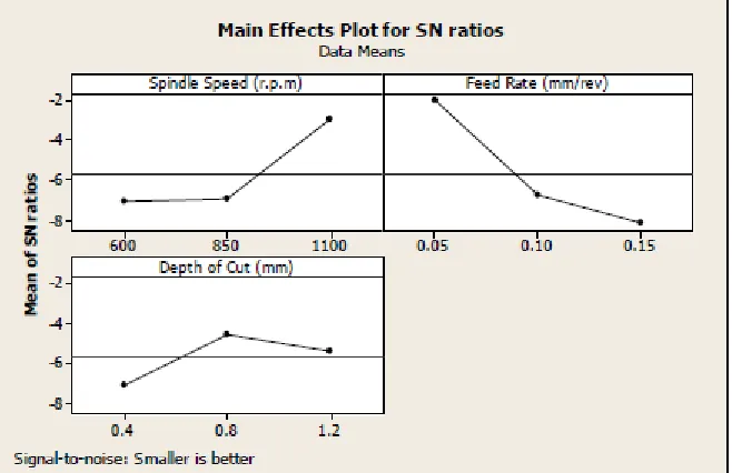
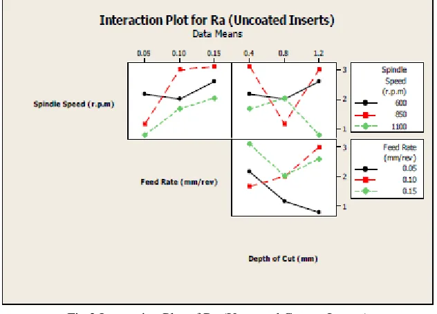
The effect of various types of input factors on the surface roughness values is given in Fig 1 for SN ratios. Effect of cutting speed is increasing with increase in speed up to 1350 r.p.m and after this it is decreasing. Optimum parameters for minimum surface roughness for uncoated cermet inserts are speed 1100 rpm, doc 0.8 mm and feed 0.05 mm/rev. Fig 2 shows the interaction plot for surface roughness.
Fig 2 Interaction Plot of Ra (Uncoated Cermet Inserts) Table-2 Value of Response for SN Ratios for Uncoated Cermet Inserts
From Table, it has been found that feed is the factor which affects the roughness more effectively than the other factors. Mean Value of Ra for Uncoated Cermet Inserts
μA2B2C3= A2 + B2 + C3-3T = -2.952-2.052-4.569-3*2.08= -15.813μm
Variation factor analysis of SN curve for surface Roughness of Uncoated cermet inserts.
In table 5.3 variation factor analysis of SN curve for surface roughness of uncoated cermet insert is listed. As observed in experiment, feed is proved to be the most important factor in surface roughness
Effect of Speed, Feed and DOC on Surface finish of Single Coated Cermet inserts
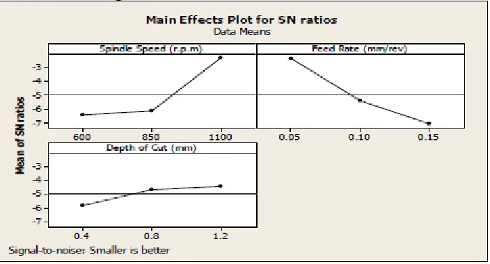
In Fig 3 effect of input factors on surface roughness in illustrated. Using the appropriate parameters for surface roughness on single coated cermet inserts results in speed of 1100 rpm, DOC 1.2 mm and feed 0.05mm/rev. Plot for surface roughness is shown below in Fig 4
Fig 3 Main Effects Plot of SN Ratios for Ra (Single Coated inserts) Table 4 Value of Response for SN Ratios for Single Coated inserts
From Table 4, it is found feed is the parameter that affects the surface finish more effectively than the other factors. Mean Value of Surface Roughness for Single Coated inserts
μA2B2C3= A2 + B2 + C3-3T = -2.342-2.385-4.408-3*1.87 = -14.745μm
Surface finish of the material varies proportionally to the feed and speed. Effect of Speed, Feed and DOC on Surface finish of Multi Coated cermet inserts
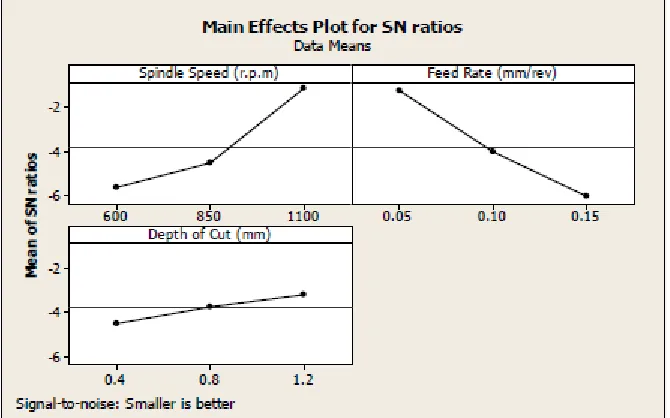
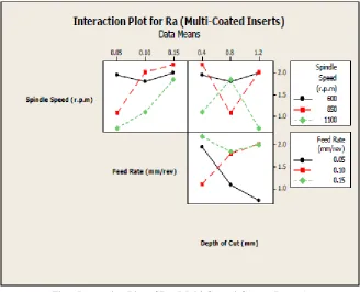
In Fig.5 effect of input factors on surface roughness in illustrated. Using the appropriate parameters for surface roughness on multicoated coated cermet inserts results in speed of 1100 rpm, DOC 1.2 mm and feed 0.05mm/rev. Plot for surface roughness is shown below in Fig.6.
Fig 5 Main Effects Plot of SN Ratios for Ra (Multi Coated Cermet Inserts) Table 6 Value of Response for SN Ratios for Multi Coated Cermet Inserts
From Table 6, it is found feed is the parameter that affects the surface finish more effectively than the other factors. Mean Value of Surface Roughness for Cermet inserts
Fig 6 Interaction Plot of Ra (Multi Coated Cermet Inserts) Variation factor analysis of SN curve for surface Roughness of Multi-coated cermet inserts.
In table 7 variation factor analysis of SN curve for surface roughness of multicoated cermet insert is listed. As observed in experiment, feed is proved to be the most important factor in surface roughness.
Table 7 Analysis of Variance for Ra (μm) (Coated Cermet), using Adj. SS for Tests
It is evident from the above analysis that the surface finish of the material varies proportionally to the feed and speed.
Optimum parameters for roughness were obtained and the result shows that the surface finish improves with the coated cermet inserts as compared to the uncoated and single coated inserts.
4. CONCLUSION
• Optimization of the different cutting parameters based on the experimentation
• Feed and speed are the significant factors which affects Ra. Optimum parameters for minimum surface roughness are Speed 1100 rpm, doc 1.2 mm and feed 0.005 mm/rev in case of multilayer coated inserts
6242S‖,Journal of Materials Processing Technology.
[7] Choy K.L., (2003), ―Chemical vapour deposition of coatings‖, Journal of Progress in Materials Science 48, pp.57–170.
[8] Thomas, T.R.,(1999), ―Rough Surfaces‖, 2nd ed., Imperial College Press, London.
[9] Krishankant, Taneja Jatin, Bector Mohit, Kumar Rajesh, (2012), ―Application of Taguchi Method for Optimizing Turning Process by the effects of
Machining Parameters‖, International Journal of Engineering and Advanced Technology (IJEAT) ISSN: 2249 – 8958, Volume-2, Issue-1.
[10] N. RichardAnd D. A spinwall, (1989), ―Use of Ceramic Tools for Machining Nickel based Alloys‖. Journal of Int. J. Mach. Tools Manufact. Vol. 29,
No. 4, Pp.575-588.
[11] N. Narutaki, Y. Yamane, Hiroshima University; K. Hayashi, Kyocera Corporation; T. Kitagawa, Kitami Institute of Technology - Submitted by K.
Uehara, (1993), ―High-speed Machining of Inconel718 with Ceramic Tools‖, Kitami Institute of Technology.
[12] Igor Yu Konyashim, (1995), ―Wear- resistant coatings for cermet cutting tools‖, Journal of Elsevier surface and coating Technology, Vol. 71 , pp.
284-291.
[13] T. I. El-Wardany, E. Mohammed and M. A. Elbestawi, (1996),―Cutting Temperature Of Ceramic Tools In High Speed Machining Of
Difficult-To-Cut Materials‖ Journal of Pergamon Vol. 36. No. 5. Pp. 611-634.
[14] Y.S. Liao, R.H. Shiue, (1996), ―Carbide tool wear mechanism in turning of Inconel 718 super alloy‖ Journal of Elsevier Science, Wear 193, pp.6-24.
[15] Zhao Jun, Deng Jianxin, Zhang Jianhua, Ai Xing, (1997), ―Failure mechanisms of a whisker-reinforced ceramic tool when machining nickel-based
alloys‖ Journal of Elsevier Science B.V., Wear 208, 220–225.
[16] K. Vandierendonckx, M. Van Stappen, (1997), ―Study of the performance of PVD and PCVD coated cermets for different cutting application‖,
Journal of Elsevier Surface and Coatings Technology, Volume 97, pp. 218-233.
[17] Ai Xing *, Zhao Jun, Huang Chuanzhen, Zhang Jianhua, (1997), ―Development of an advanced ceramic tool material—functionally gradient cutting
ceramics‖, Journal of Elsevier Science.
[18] Chonghai Xu,, Xing Ai, Chuanzhen Huang, (2001), ―Fabrication and performance of an advanced ceramic tool material‖ Journal of Elsevier Science
B.V., Wear 249 503–508.
[19] A.K. Ghani, I.A. Choudhury*, Husni, (2002), ―Study of tool life, surface roughness and vibration in machining nodular cast iron with ceramic tool‖,
Journal of Materials Processing Technology 127, 17–22.
[20] D. Dudzinski, A. Devillez a. A Moufki a, D. Larrouque’ re b, V. Zerrouki b, J. Vigneau b,(2003), ― A review of evelopments towards dry and high
speed machining of Inconel718 alloy‖ , Journal of Elsevier.
[21] J. Paulo Davim*, Lui s Figueira, (2003),―Machinability evalution in hard turning of cold work tool steel (D2) withy ceramic tool using statistical
techniques’’ Journal of Elsevier.
[22] Gerard Poulachon*, B.P. Bandyopadhyay, I.S. Jawahir, Sebastien Pheulpin , Emmanuel Seguin, (2004),―Wear behavior of CBN tools while turning
various hardended steels’’, Journal of Elsevier Science, Wear, pp. 302-310.
[23] I.J. Yang, (2004), ―Wear coefficient of tungsten carbide against hot-work tool steel disc with two different pin settings‖, Journal of science Direct