E-ISSN 2308-9830 (Online) / ISSN 2410-0595 (Print)
Supervisory Android for Network Sensor Wireless WI-FI/ZIGBEE
ALICE COSTA DE OLIVEIRA1, BÁRBARA RAMOS DE OLIVEIRA2, OTÁVIO RODRIGUES GOMES3, STÉPHANE RODRIGUES DA SILVA4, FABIANO PEREIRA BHERING5,
LINDOLPHO OLIVEIRA DE ARAÚJO JÚNIOR6
1, 2, 3, 4 Control and Automation Engineering, CEFET-MG, Leopoldina-MG, Brazil 5 CEFET-MG, Department of Computer and Mechanics, Leopoldina-MG, Brazil 6
CEFET-MG, Department of Electricity and Eletronics, Leopoldina-MG, Brazil
1
[email protected], [email protected], [email protected],
4[email protected], 5[email protected], 6[email protected]
ABSTRACT
This article proposes the development of a supervisory system for wireless sensor networks using standards Wi-Fi and ZigBee networks. In this system, it is proposed a gateway that communicates between these network standards and then capture and transmit ZigBee network data to a mobile device. The article also aims to analyze network configurations, equipment and features that can influence latency supervisor - as the arrangement of devices -and each network response time.
Keywords:Android, Network Sensor, Wireless, Zigbee, Wi-fi, Supervisory.
1 INTRODUCTION
The Wireless Sensing Networks (WSN) technology consists of a set of sensor nodes capable of performing the collection of information from the environment and transmit them using a wireless network to the manager node. Besides the ability to transmit such information, a WSN is responsible for processing and monitoring them. It is at this moment enters the supervisory systems, which are a computer systems able to monitor process variables that are frequently updated [1].
In this context, the focus of this study is the development of a mobile supervisory system for wireless sensor networks integrating Wi-Fi (IEEE 802.11) and ZigBee (IEEE 802.15.4) protocols. In a Low-Rate Wireless Personal Area Network (LR-WPAN), the standard IEEE 802.15.4 is responsible for defining the protocol and the compatibility between data communication equipment, such as a data communication standard Wireless Personal Area Network (WPAN) [2]. Thus, through a gateway, communication is made between the ZigBee and Wi-Fi networks, which enables Wi-Fi supervisory system communicate with the ZigBee network devices.
The motivation that led to the creation of this system grown up of the ZigBee protocol characteristics: low power consumption, relatively
simple network structure and the ability to support hundreds of devices on the network.
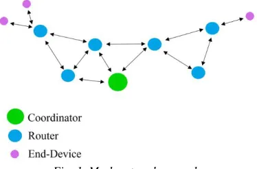
A ZigBee device can be configured to operate on the network as a coordinator, a router or an end device. As coordinator, ZigBee will be responsible for managing the network. As a router, to expand the network range, transferring data when requested. Finally, as an end device, where sensors and actuators are usually installed, commands can be send to this device or it can transmit information collected by it. In addition, this latter configuration has the interesting feature of acting in Sleep mode, when the device is able to go into sleep state mode and only activated when required by the network, which allows an energy saving as the power consumption it is not constant.
ZigBee devices, with their settings, may have some arrangement such as the mesh network as in Figure 1. The mesh network allows for communication between the coordinator and the device path redundancy for traffic information, such that in the absence of a router, another replaces, redoing the communication bridge.
Therefore, the aim of this article is to create a gateway to a supervisory system that has a relatively low cost of development and allow the monitoring of variables such as temperature and humidity. An application was developed for the Android platform, allowing access to these variables at any time and in real time via Wi-Fi network. With this application, the intention is to demonstrate by testing the functionality of this medium and possible physical interferences or network overloads.
2 COMMUNICATION TECHNOLOGIES
WIRELESS
Wireless networks are being increasingly used for its ease of installation and because it is a user-friendly technology. In this context, the Wireless technology allows the transfer of information between two or more points without the need for physical connection. As an example of technology for wireless communication can mention the
Bluetooth, Wi-Fi, WiMax (Worldwide
Interoperability for Microwave Access), RFID (Radio Frequency Identification), and the ZigBee technology.
Bluetooth is the standard for wireless networks that allows connections with short distance of 10 - 100 meters. The main advantages of Bluetooth refers to the low cost for small networks, allowing transmission of voice and data, and is easily integrated into TCP / IP protocols. On the other hand, such drawbacks may be mentioned low range and limitation on the devices used. Due to its limitation in relation to energy consumption, the Bluetooth protocol is not recommended for applications that use long-term connections. Wi-Fi technology can be defined as a local area network (LAN) operating by means of radio waves providing Internet within a limited range. Just as Bluetooth, Wi-Fi requires a lot of your battery not being recognized as an efficient network of energy. WiMax technology offers wireless data transfer at high speeds and for longer distances [3]. Moreover, RFID is a technology for identifying, tracing and managing products and documents without the need of a physical or visual contact. All of these technologies have the disadvantage of making an increased power consumption. In order to overcome
this limitation, emerged the protocol for wireless data transfer, ZigBee.
Because of the great discoveries and
technological innovations in wireless
communication, it is possible to develop sensing distance. Then comes the concept of sensors wireless network (RSSF). This network is characterized by a lot of sensors node able to communicate and allow the best network management. Compared with wired networks, the RSSF does not have the disadvantage of high cost with cabling, and can be installed in hard to reach places.
3 PROTOCOL ZIGBEE
ZigBee is a protocol that uses the IEEE 802.15.4 standard as a basis to define the layer physical PHY (Physical Layer) and enlance, also known as Access Control Layer to Middle MAC (Medium Access Control). The ZigBee protocol is composed of layers, with a hierarchical structure based on the OSI (Open Systems Interconnection). However, unlike the OSI which has seven layers, ZigBee protocol defines only the layers required to achieve a desired set of features [4]. The IEEE provides the standardization of wireless networks for physical and enlace layer levels. The Figure 2 shows the layers of ZigBee protocols.
Fig. 2. ZigBee Protocol Layers [5]
physical layer uses the DSSS modulation (Direct Sequence Spread Spectrum) incorporating in each data bit a redundancy standard of and spreads the bandwidth used. This redundancy allows not only that data are identified as belonging to a particular node, but also enables detection of errors [4].
The MAC layer is responsible for the data encapsulation process from the upper layers preparing them to be transmitted, that is, this layer is responsible for defining the access method and the rules of communication between the different stations [4],[6].
The data transmission between ZigBee devices can be performed via two communication modes: AT (Application Transparent) and API (Application Programming Interface). The ALT mode is used for simple applications from text commands, which is clear to the user what is being sent and received [7]. On the other hand, in API mode the user now has more access to information transmitted. In this way, data transmission is made from frames, hexadecimal data packets with a fixed structure and established by the ZigBee Alliance, setting operations, or events within the ZigBee module [7]. This method allows greater control over the data transmission. Figure 3 shows the structure of a frame.
Fig. 3. Structure of a frame [8]
In a ZigBee network can be three types of devices: Coordinator, Router and End Device. The ZigBee protocol makes the distinction between these three logical devices, as described in Table 1. It is noteworthy that, in terms of hardware, all ZigBee devices are equal. What differentiates them is in software level, depending on the network configuration in which they are inserted [4].
TABLE 1: TYPES AND FEATURES OF THE DEVICES [9]
Device Function
Coordinator
Coordinators are the most capable of the three node types. There is exactly one coordinator in each network
and it is the device that establishes the network originally. It is able to store information about the network,
including security keys.
Router
Routers act as intermediate nodes, relaying data from other
devices. Routers are commonly used to extend the
network.
End device
End Devices, usually sensors, can be low-power / battery-powered devices. They have sufficient functionality to talk to their parents (either the coordinator or a router) and cannot relay data from other
devices.
The ZigBee protocol has three main features: low power consumption, low cost and low data rate (250Kbps), unlike Wi-Fi which can achieve data transfer rates of 11Mbps to 55Mbps, or Bluetooth that can achieve the rate up to 55Mbps [8]. Despite presenting a low data transmission rate, devices ZigBee are more sensitive to a lesser extent, simple protocol, with transfer data securely, especially when compared to other wireless network standards such as Wi-Fi protocols and Bluetooth. Furthermore, it can be said that the ZigBee protocol has a low-latency communication, this is, quick response, as will be demonstrated in test session this paper, and allows grouping a large number of nodes on a single network (65,000 nodes) [5]. Its application is very common for industrial control and monitoring, home automation, embedded sensing and automation of power systems [8].
4 ZIGBEE'S TECHNOLOGY
APPLICATIONS
With the increasing application of ZigBee modules, there was the need to make monitoring data through mobile devices. These devices do not have any form of direct communication with the ZigBee protocol, therefore, it is necessary to find solutions to make this possible.
In some works already developed it is very common to use a Dongle, equipment built into the mobile device to work with the ZigBee protocol.
One possible use of these systems is in home automation. In [10], the communication was made between two Android devices via a dongle connected to the USB port of each. In this work, one of the aims is to realize the traffic of messages between the two devices via an application, ZigBeeComm, which was developed for this system. In [11] and [12], it is using the dongle also with a very similar application.
device connected to the router, a considerable reduction in energy consumption was possible.
The use of the dongle proved efficient in these works, but the fact of having to attach a new device to your smartphone leaves the solution as not feasible.
In [14] has implemented a monitoring system of an electric bicycle, which has various operating sensors. It is made monitoring both the physical device, which is the bicycle, the variables related to the current state of the biker, such as heartbeat. What differs this previous project is the use of a MicroSD card ZigBee, shown in Figure 4. This MicroSD card is another communication option and performs the same function Dongle.
Fig. 4. ZigBee MicroSD cards (A e B) and USB Dongle CC2531 (C) [13]
Another way to make the communication between Wi-Fi and ZigBee network is using the Arduino. Thus, there is no need of using Dongle or MicrosSD. In [15], Arduino was used with a module, which was coupled to the ZigBee shown in Figure 5, and thus it became possible to transmit data. Once converted and have the Wi-Fi network could be accessed via a smartphone connected to the network. The idea of this work is very similar to that developed in this article. The difference is that we chose not to use any microcontroller for data transmission.
Fig. 5. Wi-Fi and ZigBee module are integrated on the mother board of the Arduino [15]
5 PROPOSED SYSTEM
In this work, a gateway for the development of a supervisory system is proposed that captures and transmits data from a wireless sensor network Zigbee to a mobile device. The sensor is coupled to an XBee device set to End Device (ED) which relays the data to Xbee 's willing routers in a mesh network. Xbee 's modules are designed to work in a Zigbee network. This network architecture was chosen as a function of allowing two or more ways for data transmission reducing potential data loss problems in the case of a device failure. In this type of network there is a XBee coordinator (CO) that receives data from the XBee 's routers. In each network there is only one coordinator who is responsible for managing the ZigBee network. To integrate between ZigBee network and the Wi -Fi network has developed a gateway that connects the XBee coordinator modules to the XBee Wi -Fi module. XBee Wi -Fi is the device that makes communication and data exchange with the network without thread. The schematic design can be seen in Figure 6.
The sensor used was a DHT 11, manufactured by D_Robotics, a stable sensor and which is fed with a voltage of 3V and 5V DC. This sensor was chosen due to present a measurement range of 0 to 50 ° C and have a moisture precision error ± 5% and ± 2 ° C temperature, which met the specifications of the project [16].
In the schematic end device is programmed to receive the temperature data and the humidity DHT one sensor 11. The sensor data are sent from the DF configured as Xbee for Xbee's routers. The ZigBee network with XBee's routers transfer data to a gateway that communicates with the router passes them on to the end device.
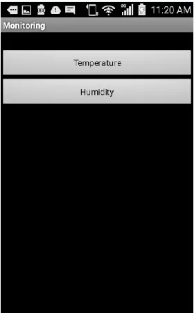
To receive the sensor data was developed an Android application using the Java language. The application was developed using the Eclipse platform, which is an IDE RAD development for Java, along with an SDK (Software Development Kit), a software development kit designed to work with Android applications. The interface has been developed to become visually as simple as possible so that users familiar with technology or not had no difficulty in using the application. The measuring screens (Figures 7, 8 and 9) have been developed to monitor the supervisory system.
Fig. 7. Application home screen
Fig. 8. Temperature screen
To connect the mobile device to the XBee Wi-Fi was necessary to use a connection by socket, which is a communication mechanism used on a TCP / IP network. In connection socket there is a server that is open to connections. Once a client establishes a connection both the server and the client can hold a conversation. The form of connection and comm-unication depends on the application implementa-tion. In the developed application, a server socket is created to receive a connection. Once a client is connected, then the XBee Wi-Fi, the client sends to the server the sensor data.
The results could be represented in graphical form through the storage and processing of sensor data in a database. However, this representation is not part of the scope of this article.
Although the application has been used only for monitoring, it could also have been used as actuator in the supervisory system, which will be subject to future developments.
6 IMPLEMENTATION OF THE
GATEWAY
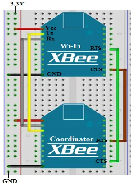
To connect the ZigBee network to the Wi-Fi network was necessary to make the serial communication between the XBee Wi-Fi and XBee Coodenador. The report has been made so that the TX port of a Xbee be connected to the RX port of the other Xbee. The RX and TX ports are responsible for transferring data from one device to another. TX is responsible for making the sending of the data and the RX port is receiving them.
You also need a serial connection between the RTS and CTS pins of the devices. RTS and CTS are ports responsible for making the flow control between the sending and receiving of information in API mode.
Serial communication was necessary because unlike the devices configured as a coordinator, router or end device communicating over the ZigBee network, the XBee Wi-Fi device communicates with the Wi-Fi network and not with the ZigBee network. The serial port via connection can be seen in Figure 10.
In the schematic of Figure 10 XBee coordinator and the XBee Wi-Fi are fed a 3.3V voltage. Both the GND when the voltage is common to both devices.
Fig. 10. Gateway circuit
For the configuration of the modules was used XCTU program developed by Digi company also developer of the Xbee's modules used in the project. Each module has been configured with the same PAN ID (Personal Area Network) so that everyone was on the same network. It was also specified an NI (Node Identifier) corresponding to the name of each device. Since the intention was to make all devices to communicate and allow the expansion of ZigBee network was used the DH parameters (Destination Address High) and DL (Destination Address Low) as broadcast on the devices.
At the end device, beyond this parameter was also set up the SM (Sleep Mode) as Cyclic Sleep and ST parameters (Time Before Sleep) and SP (Cyclic Sleep Period). The final device is set in sleep mode so that it went into sleep mode during the period of time that was not being used making it possible to reduce energy costs. ST is the time before the Xbee enter sleep mode and SP is the period in which the end device remains inactive. For the purpose of testing the ST was set to 157F x 1ms (5503ms) and the SP as 1F4 x 10ms (5000ms). In an SP coordinator parameter was also specified that because the coordinator SP determines the transmission timeout and sending data to the end device. XBee that the SP was set to 226x10ms (2260ms). SN (Number of Cyclic Sleep Periods) was specified as 5. SN is the number of periods in which the end device can join the coordinator. If the end device is not associated to the coordinator during that time, the coordinator loses its association with the end device.
In the XBee Wi-Fi it was necessary to activate the Scan the network and connect the device to the router. The IP (IP Protocol) is set to TCP / IP and MA (IP Addressing Mode) was placed as static. The connection was defined as static so that they could access the IP address of the XBee by the mobile device via the socket connection. The MK address (IP Address Mask), network mask has been specified as the default network and the GM (IP Address of Gateway) as the router network specifications.
The RTS and CTS pins on the XBee Wi-Fi and XBee Coordinator were configured as 1 as specified in the gateway developed.
7 TESTS AND RESULTS
The stage set for the tests was the building of Engineering at the Federal Center of Technological Education of Minas Gerais - Campus Leopoldina. Two evaluations were made: a) The first was an analysis of the time between sending and receiving a packet in a Zigbee network using XBee a coordinator and end device; b) The application developed was used to measure the latency of the Wi-Fi network. The measurement was made from the sending and receiving a mobile package to the end device. The analysis was performed by the intensity of the mobile signal and XBee Wi-Fi connection to the router and the response time between a sending and receiving package in supervisory.
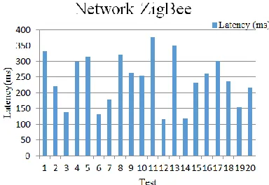
In the first evaluation, to check the ZigBee network response time we used a frame to connect the devices to ZigBee network. Sending the frame it was done by XCTU program with the Coordinator associated with the computer via the USB port. XCTU the media-the time between sending and response (latency) of the frame sending Coordinator for the end device. Where 20 measurements were performed the data transfer rate on the Zigbee network was between 100 and 400ms. Measurements are arranged in Figure 11.
Fig. 11. Latency ZigBee network depending on the number of tests performed
With the information set forth in Figure 1 has been possible to determine the average time between sending and receiving the frame in the Zigbee network. To calculate the time used the harmonic mean. often used to make estimates of typical rates of change values [19]. It was chosen because it presents a result that is always less than or equal to the arithmetic mean. How is desired average latency throughout the harmonic mean interval test is considered more accurate. The harmonic mean is calculated using the formula:
(1)
Where:
mh is the harmonic mean
xi are the samples
n is the number of samples From the use of Equation 1, we calculated the average time data transmission between the sending and receiving a package in the ZigBee network. The average time was 218,1ms considering all nearby devices.
In the second evaluation were used the mobile, gateway, router and end device. Four scenarios were evaluated: a) the first scenario with all near the router devices; b) the second scenario with the Gateway away from the router and the mobile near the Gateway; c) a third party with the mobile device away from the router and Gateway near the router; d) and the fourth scenario with the Gateway away from the router and the mobile device away from the Gateway. In both scenarios were carried out in which 50 tests 20 were repeated more values were withdrawn and used as the basis for analysis of the supervisor.
7.1 Scenario 1 - Gateway and router near
Fig. 12. Latency's supervisory in Scenario 1
Using the harmonic mean was possible to detect the average time of supervisory response. The average time calculated was 1169,85ms.
7.2 Scenario 2 - Gateway and mobile device
away from the router
In the second scenario tested again latency Wi-Fi network, but with the gateway away from the router, so that the signal loss between them was considerable. The mobile was near the gateway. In this scenario there was a loss of signal strength between the router and gateway 68db and 70db loss between the mobile and the gateway. Analyzing the graph of Figure 13 it was found that the latency between the supervisory was 3000ms and 4000ms.
Fig. 13. Latency's supervisory in Scenario 2
Using the harmonic mean was possible to detect the average time of supervisory response. The average time calculated was 3370,73ms.
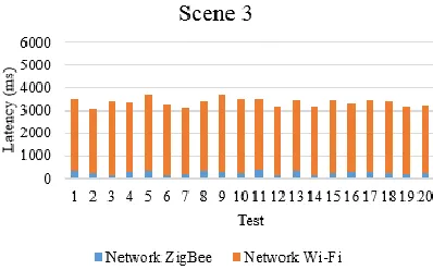
7.3 Scenario 3 – Gateway and remote router
and mobile device near Gateway
For the tests in the third scenario the gateway was placed next to the router as Scenario 1 and only the mobile was far away. In this scenario, it was verified a loss of signal between the router and gateway 5db and between the mobile device and the router 81db. The latency time in supervisor was
between 3000 and 4000ms. The latency for each test can be seen in Figure 14.
Fig. 14. Latency's supervisory in Scenario 3
With the information provided by the graph on Figure 14 there was a harmonic mean latency of the supervisory. The estimated average time was 3123,04s.
7.4 Scenario 4 – Dispositivo Móvel distante do
Gateway com Gateway afastado do roteador:
For the tests in the fourth scenario the gateway was left away from the router and the mobile was away again. The gateway having a 65db signal loss and the final device having a loss of 86dB. Looking at Figure 15 it was possible to verify the supervisor 's response time, between 4000 and 5000ms.
Fig. 15. Latency's supervisory in Scenario 4
The average time calculated by the harmonic mean was 4593,76ms.
8 DISCUSSION
gateway, signal loss in mobile was higher than the loss obtained by the gateway.
Comparing with Scenario 1 Scenario 3, the removal of the mobile device as well cause a considerable increase in signal loss caused a 667.35 increase in the mean time supervisory latency.
Comparing with Scenario 2 Scenario 1, the router gateway remote and proximity of it to the mobile device caused an increase of 638.95 in the mean time supervisory latency.
Analyzing the Scenario 2 relative to Scenario 3 was revealed that there was a large discrepancy between the average time of supervisory latency. Based on these data we can conclude that the gateway supports a considerable loss of signal without a large increase in the time lag of the supervisory system.
Compared to Scenario 4 Scenario 2 it is concluded that considering the loss of signal next gateway on both scenarios the removal of the final device causes an increase of the average time 198,07ms supervisory latency.
As the signal loss in the gateway in scenario 2 was less than the signal loss on the mobile device also concludes that the XBee Wi-Fi, which communicates with the router can have a better communication with the network of the mobile device.
Considering both scenarios, with the results we see that the removal of the mobile brought more instability to the supervisory system than the gateway clearance.
9 CONCLUSION
As the proposal was to verify the functionality of a system sought to verify the efficiency of data transmission between the mobile device and the ZigBee network. After the tests and results we observed that the ZigBee network response time is much shorter than the time of Wi-Fi network response.
In mounting a supervisor had to take into account the factors that influence both the Wi-Fi network as the ZigBee network. The removal of devices caused a significant increase in the latency time of the analyzed scenario.
Compared to other works the Zigbee network response time was less than what was forecast in other projects. [18]
The advantage of using a gateway rather than other technologies such as Dongle [10] and the Arduino [15] is that in assembling the supervisor was not necessary to use a physical device connected to a mobile device or had to use a
controller to monitor traffic between messages. Everything was done through the application.
The disadvantage of this system is equipment configuration complexity and difficulty of finding software that can do an analysis of the Zigbee network without need to use the serial output of a device.
10 REFERENCES
[1] C. C. DE MORAES, P. L. CASTRUCCI (2013). Engenharia de Automação Industrial. 2nd ed. Editora LTC – Livros Técnicos e Científicos, Rio de Janeiro, Brasil.
[2] IEEE, Computer Society. IEEE Standart for local and metropolitan area network: Part 15.4: Low-Rate Wireless Personal Area Networks
(LR-WPANs). 2011. Disponível em:
<http://standarts.ieee.org/getieee802/download/ 802.15.4-2011.pdf> Acesso em: 14/02/2016. [3] J.S. Lee, Y.W. Su, C.C. Shen, “A Comparative
Study of Wireless Protocols: Bluetooth, UWB, ZigBee, and Wi-Fi”, The 33rdnAnnual Conference of the IEEE Industrial Electronics Society (IECON), Nov. 5-8, 2007, Taipei, Taiwan.
[4] R.R. Archana, L.G. Malik, “ZigBee: The
Emerging Technology in Building
Automation”, International Journal on Computer Science and Engineering (IJCSE), Vol. 3 No. 4 Apr 2011.
[5] G. Kaur, K. Ahuja, “QoS measurement of Zigbee home automation network using various modulation schemes”, International Journal of Engineering Science and Technology (IJEST), 2011.
[6] J.R.C Fonseca, M.C Carneiro, A.B Lugli, J.P.C Henriques, “Supervisão de Sistemas Industriais Utilizando Rede Sem Fio”, Brazil Automation (ISA), Transamerica Expo Center, São Paulo, 2014.
[7] KAI, C.M and CHIA,T.J, “Wirelles
Tecnologies: Concepts, Methodologies, Tools and Applications”.Vol 1.United States of America. IGI Global,2012.
[8] ELAHI, A; GSCHWENDER, Adam. "ZigBee Wireless Sensor and Control Network" 1. ed. United States of America: Prentice Hall, 2009. [9] Digi International Inc, White Paper: Wireless
Mesh Networking ZigBee® vs. DigiMesh™. 2008.
[11]A.C. Olteanu, G.D. Oprina, N. Tapus and S. Zeisberg, “Enabling mobile devices for home automation using ZigBee”, IEEE 19th International Conference on Control Systems and Computer Science, 2013, pp. 189-195. [12]B.S.C.T. Reddy, N.S. Teja and G.V.V.
Sharma, “Android controlled Zigbee motes for Wireless Sensor Networks”, IEEE 11th International Conference on Mobile Ad Hoc and Sensor Systems, 2014, pp.525-526. [13]T. Jin, G. Noubir and B. Sheng, “WiZi-Cloud:
Application-transparent Dual ZigBee-WiFi Radios for Low Power Internet Access”, IEEE INFOCOM, 2011, pp.1593-1601.
[14]A.L. Ferreiro; I.P. Garcia; M.C. Rodriguez, “Sistema de Sensorização Móvel e Controlo baseado em ZigBee para Bicicletas Elétricas”. Annual Seminar of Automation, Industrial Electronics and Instrumentation SAAEI 2012, in Tecnologias del Aprendizaje, IEEE Revista Iberoamericana, Aug. 2013, vol.8, no.3, pp.133-134.
[15]K.Y. Lian, S. JungHsiao and W. TsaiSung, “Intelligent multi-sensor control system based on innovative technology integration via ZigBee and Wi-Fi networks”, ELSEVIER
Journal of Network and Computer
Applications, 2013, pp.756-767.
[16]D_Robotics “DHT11 Humidity & Temperature Sensor”, 2010. Disponível em: < http://www.micropik.com/PDF/dht11.pdf >. Acesso em 15 de Fevereiro de 2016.
[17]Digi Internacional Inc, “Xbee ® /Xbee-Pro® RF Modules”, 2009. Disponível em: < https://www.sparkfun.com/datasheets/Wireless /Zigbee/XBee-Datasheet.pdf >. Acesso em 15 de Fevereiro de 2016.
[18]L.D.Lacerda, “Análise desempenho de uma rede de sensors em malha utilizando o padrão Zigbee”, Centro Federal de Educação Tecnológica de Minas Gerais, 2015.
![Fig. 2. ZigBee Protocol Layers [5]](https://thumb-us.123doks.com/thumbv2/123dok_us/1329434.1641181/2.612.320.516.440.689/fig-zigbee-protocol-layers.webp)
![TABLE 1: TYPES AND FEATURES OF THE DEVICES [9]](https://thumb-us.123doks.com/thumbv2/123dok_us/1329434.1641181/3.612.313.524.92.188/table-types-features-devices.webp)
![Fig. 4. ZigBee MicroSD cards (A e B) and USB Dongle CC2531 (C) [13]](https://thumb-us.123doks.com/thumbv2/123dok_us/1329434.1641181/4.612.340.508.388.710/fig-zigbee-microsd-cards-b-usb-dongle-cc.webp)