R E S E A R C H
Open Access
Design framework for reliable and
environment aware management of smart
environment devices
Adja Ndeye Sylla
1*, Maxime Louvel
1and Eric Rutten
2Abstract
A smart environment is equipped with numerous devices (i.e., sensors, actuators) that are possibly distributed over different locations (e.g., rooms of a smart building). These devices are automatically controlled to achieve different objectives related, for instance, to comfort, security and energy savings. Controlling smart environment devices is not an easy task. This is due to: the heterogeneity of devices, the inconsistencies that can result from communication errors or devices failure, and the conflicting decisions including those caused by environment dependencies. This paper proposes a design framework for the reliable and environment aware management of smart environment devices. The framework is based on the combination of the rule based middleware LINC and the automata based language Heptagon/BZR (H/BZR). It consists of: an abstraction layer for the heterogeneity of devices, a transactional execution mechanism to avoid inconsistencies and a controller that, based on a generic model of the environment, makes appropriate decisions and avoids conflicts. A case study with concrete devices, in the field of building automation, is presented to illustrate the framework.
Keywords: Smart environments, Reliability, Transactional middleware, Automata language
1 Introduction
Smart environments are equipped with numerous devices that are automatically controlled to achieve different objectives. For instance, a window can be opened to cool or ventilate a room. Controlling smart environments devices raises several problems. First, devices are built by different manufacturers and use heterogeneous com-munication technologies. Second, a device may become unreachable due to a hardware failure or a communica-tion error. In this case, a command sent to this device is not received and the corresponding action is not per-formed. Assuming that the action has been performed leads to a runtime inconsistency (inconsistency in the rest of the paper). For instance, sending the command closeto a door and assuming that it is closed becomes an inconsistency if the door remains opened due to a com-munication error or a failure. Third, the decisions taken to achieve the objectives may be conflicting or violate other
*Correspondence: [email protected]
1Université Grenoble Alpes, CEA, LETI, DACLE, LIALP, F-38000 Grenoble, France Full list of author information is available at the end of the article
objectives. Conflicts and violations are either explicit or implicit. Implicit conflicts and violations are due to envi-ronment dependencies and are not easy to detect. For instance, opening a window to cool a room can raise the noise level (resp. the CO2concentration). This can violate an objective that limits the room noise level (resp. the CO2 concentration) at a given threshold.
In the literature, several solutions have been proposed for the reliability of smart environments [1–16]. These solutions use different methods (e.g., model checking, pairwise comparison of rules) to prevent from explicit and/or implicit conflicts and objectives violations. How-ever, using these solutions requires to manually program or model the behaviour of the smart environment. Then, the program or the model is verified to detected specific errors (e.g. conflicts). If an error is detected, the program or the model is manually modified and verified again. This can be tedious because developers have to consider all the combinatorial possible cases. Moreover, these solutions do not handle the inconsistencies due to communication errors and hardware failures.
This paper proposes a design framework for reliable and environment aware management of smart environment devices. The proposed framework allows for
• Declarative management of devices, by specifying the target objectives and not how to reach them;
• Avoidance of both explicit and implicit conflicts;
• Avoidance of inconsistencies that are caused by communication errors and hardware failures.
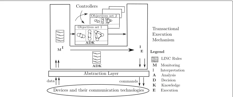
The framework is based on the combination of a rule based transactional middleware (LINC [17]) and a reac-tive language (Heptagon/BZR [18]). As shown in Fig. 1, the proposed framework enables the autonomic manage-ment of devices through a variant of the MAPE-K loop [19] called MIADIE-K (Monitoring, Interpretation, Anal-ysis, Decision, Interpretation, Execution and Knowledge) and consists of:
• An abstraction layer: To deal with the heterogeneity of smart environment devices;
• A transactional execution mechanism: To prevent from the occurrence of inconsistencies;
• An environment aware controller: To make appropriate decisions and prevent from both explicit and implicit conflicts. The controller relies on a generic model of the environment. The generic aspect of this model allows to use the same controller for other environments that have the same types of devices (e.g., rooms of a building).
To improve environment monitoring, the proposed framework allows developers to design monitoring rules, in LINC, and create soft sensors from physical sensors. A soft sensor aggregates or transforms the data of one or more physical sensors. The framework also allows
developers to design rules that perform actions on the environment assuming that these rules do not interact with potential conflicting devices (which must be handled by the environment aware controller).
The paper is structured as follows. Section 2 gives the background material. Then, Section 3 describes the pro-posed framework. Section 4 presents how devices are managed using the framework. Section 5 illustrates the framework through a case study, with concrete devices, in the field of building automation. Section 6 discusses related work. Finally, Section 7 concludes the paper and presents the future works.
2 Background
The proposed framework relies on a transactional mid-dleware and a reactive language that supports the synthe-sis of controllers. The transactional middleware enables the communication with devices and avoids inconsis-tencies. The reactive language enables the declarative management of devices while preventing from conflicts and objectives violations. In this paper, the transactional middleware LINC [17] and the reactive language Hep-tagon/BZR [18] are used.
2.1 LINC middleware
LINC [17] is a rule based middleware used to develop and deploy distributed applications. It has been used in several domains such as building automation [20–22] and wireless sensor networks [23–25].
2.1.1 LINC concepts
LINC relies on three paradigms:
• Associative Memory[26]: It is implemented as a set of distributed tuple spaces containing resources (tuples of strings). In LINC, tuple spaces are called
bags. They are grouped, according to the application logic, in objects. Resources are used to model the entities of an application and are manipulated using three operations:rd, get and put. The rd is used to verify the presence of a resource in a bag. Theget is used to remove a resource and theput is used to insert a resource. These operations are used in production rules.
• Production Rules[27]: A production rule consists of two parts: aprecondition and a performance. In the precondition, the operationrd is used, with a partially instantiated resource as parameter, to verify specific conditions in the system (e.g., presence detected). If these conditions are true, the
performance is triggered. The performance uses the three operations. Therd is used to verify conditions. Theget and the put are used to perform actions on the system and update its logical state (i.e., resources stored in LINC bags).
• Distributed Transactions[28]: They are used in the performance part of a rule. A transaction allows to group as one operation the verification of conditions (rd ), the realisation of actions (put), and the update of the system logical state (get, put). Thus, the performance part of a rule may abort if, for instance, the verification of a condition through ard operation is no longer true. The performance part also aborts if aput operation fails because the corresponding action (e.g., switch on a lamp) cannot be performed (e.g., due to a communication error or a hardware failure).
2.1.2 LINC in the context of smart environments
LINC provides a framework called PUTUTU [20, 21] that enables the communication with devices and hides their heterogeneity. PUTUTU consists of several LINC objects. As shown in Fig. 2, these objects encapsulate
different technologies (e.g.,TelosB,LON,Tellstick) and inherit from four generic objects:
• Object_dongles_modules: It is used to manage a dongle or any other equipment plugged in an ethernet or a USB port. The dongle allows to communicate with the devices of a specific
technology. It has two bags:Type and Location. Type associates the id of a device to its type.Location associates the id of a device to its location.
• Object_wsan_sensors: It is used to manage sensors. It has one additional bag calledSensors which associates the id of a sensor to its latest measured value, in the format(id, value).
• Object_wsan_actuators: It is used to manage actuators. It has one additional bag calledActuators which is used to send commands to the actuators. The resources of this bag are in the format(id, command, parameters). The insertion of such a resource, using the operationput, actually sends the command to the specified actuator.
• Object_wsan_sensors_actuators: It is used to manage technologies providing both sensors and actuators (e.g. EnOcean). This object is derived from the two previous generic objects and inherits from their bags (e.g.,Sensors, Actuators).
2.1.3 LINC rule example
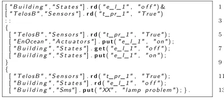
Listing 1 presents an example of a LINC rule that switches on the lamp of a room when a presence is detected. This room is equipped with a TelosB presence sensor and an EnOcean lamp actuator.
This rule consists of two parts: a precondition (before the symbol ::) and a performance (after the symbol ::). The precondition consists of ardon the bagStates contain-ing the logical stateoffand ardon the bagSensorsof
theTelosBobject to detect a presence. When the lamp is off, the rule waits for a resource indicating a presence in the room. This triggers the performance. The perfor-mance consists of two transactions (between {}). The first transaction verifies if the presence is still detected (line 5), sends the command to the lamp (line 6) and updates its logical state (lines 7 and 8). LINC ensures that all the actions are done or none of them. Hence, if theput operation fails on the actuator (e.g., communication error, actuator failure), the lamp stays off in the bagStates.
If no error occurs in the first transaction, the second transaction will fail at line 12 (the lamp is now on). If the presence is not detected anymore, both transactions will fail (lines 5 and 11). Finally, if the lamp cannot be switched on (e.g., due to a communication error), the second trans-action will send a SMS to the maintenance team to inform them of the problem.
Executing this rule in another room simply requires replacing the PUTUTU objects (i.e., TelosB and EnOcean) and the ids (i.e., t_pr_1, e_l_1), respec-tively, by the communication technologies and the ids of the room presence sensor and lamp actuator.
2.2 Heptagon/BZR language
Heptagon/BZR or H/BZR [18] is a language used to build reactive systems, by means of automata and equations. It enables model checking to verify properties (e.g., absence of objectives violations) and especially the synthesis of controllers to enforce properties.
2.2.1 Design of a H/BZR program
A H/BZR program is designed as a set of blocks called nodes. A node has input flows and output flows. It con-tains equations defining output flows in terms of input flows, local variables, and possibly intermediate states variables. These equations can be encapsulated in states of automata. They can also instantiate other nodes. Each node can be provided with a contractthat defines a set of properties to be enforced on the program. These prop-erties are enforced, at compilation time, through discrete controller synthesis [18].
Automaton consists of states, one of them being the initial state, and transitions between them. States are
associated to equations that give specific values to the out-put flows of the automaton node. The value of an outout-put flow must be defined at each instant. Transitions are asso-ciated to boolean expressions related to one or several input flows of the automaton node.
Figure 3 presents an automaton modelling a lamp. This automaton is contained in a node that has two input flows (c1,c2) and two output flows (cmd,lum). The automaton has two states (Off,On) and two transitions. Each state is associated to two equations that give values to the
out-put flows. The equation cmd = s_off → nothing
means that at the state Off, cmd is equal to s_off (switch off ) if this state is newly activated andnothing otherwise. The reason is twofold. First, the value of an output flow must be defined at each instant. Second, this prevents from continuously computingcmd=s_off while the lamp is already off. The equation lum = 0 means that at the stateOffthe lamp provides a luminos-ity equal to 0 lux. The input flowsc1andc2are boolean variables.
The initial state of the lamp automaton isOff. In this state, when c1 is false (i.e., not c1 is true), the automaton goes to the stateOnand the output flows take the values given by the equations of this state. Otherwise (i.e.,c1istrue), the automaton remains in the stateOff. This means that in the stateOff, there is an implicit tran-sition associated toc1that allows to remain in this state. In the same way, when the automaton is in the stateOn, if c2 is true, the automaton goes to Off. Otherwise (i.e.,c2isfalse) it remains in the stateOn. There is an implicit transition associated tonot c2allowing to stay in the stateOn.
This node example could be designed using only one input flow to reduce the number of variables used. For instance,not c1andc2, in the automaton transitions, could be respectively replaced withnot candc.
Discrete controller synthesis (DCS) [18] is a formal method used to enforce a set of properties, called objec-tives, on a model. DCS is enabled by H/BZR at compila-tion time. Given a model that represents all the possible behaviours of a system and a set of target objectives, DCS
inhibits all the behaviours that violate the objectives. To do this, DCS requires to partition the variables of the con-sidered model in two sets: controllable and uncontrollable variables. Once the variables are partitioned, the DCS algorithm explores the state space of the model and com-putes the possible values of the controllable variables. The aim is to enforce the target objectives, whatever the values of the uncontrollable variables. For instance,c1andc2in Fig. 3 can be defined as controllable variables to enforce an objective related to the luminosity of a room.
After the controller synthesis, several solutions can be possible regarding the objectives to achieve. For instance, the lamp can beOfforOnto provide a luminosity greater or equal to 0 lux. However, one solution must be cho-sen. For this, the backend of the H/BZR compiler selects one of the solutions. It is possible to guide the selection with two options. Firstly, the compiler backend favours the valuetrueto the valuefalsefor a boolean variable. For instance, in the lamp automaton (Fig. 3), to favour stay-ing Off, the transition from Off to Onis associated to not c1. Here, the implicit transition that remains in the stateOff(associated toc1) is favoured by the compiler backend.
The second option is that the compiler backend follows the declaration order of the variables and gives to them the valuetrue. If this does not enforce the target objectives it changes the values tofalsefollowing the inverse of the declaration order. Hence, when declaringc1beforec2, if two transitionsT1andT2respectively associated tonot c1andnot c2are possible, the compiler backend will chooseT2. It givestrueto c1andfalsetoc2(not c2istrueandT2is chosen).
2.2.2 Execution of a H/BZR program
The compilation of a H/BZR program generates a code in C or Java. In both cases, the generated code includes a function calledstep. Thesteptakes as parameter a set of input values, computes the output values that allow to reach the target objectives, and updates the state of the automaton that models the system. One execution of the stepfunction corresponds to one reaction of the system. Therefore, thestepmust be executed each time a reac-tion is required. Executing the steprequires to ensure that the state of the automaton is always consistent with the state of the actual system. This is done by combining LINC and H/BZR.
2.3 Combination of LINC and H/BZR
LINC is designed to implement rules that react to events (e.g., production of a new sensor value). Hence, a LINC rule is used to execute thestepfunction when necessary (i.e., each time an event occurs). This rule first collects data (e.g., through sensors) and then, it invokes thestep in order to compute appropriate commands to send to
the system (e.g., through actuators). Thanks to its trans-actional guarantees, LINC ensures that a group of actions are all done or none of them is done. Thestep is thus executed in a transaction, together with the sending of the commands. Hence, if a command cannot be sent, the step is not executed and the state of the automaton stays consistent with the state of the actual system. More details on the combination of LINC and H/BZR can be found in [29].
2.4 Autonomic computing
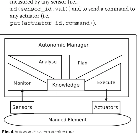
Autonomic computing [19] has been used in several solu-tions for the management of smart environment devices [30–33]. It consists in creating systems that manage them-selves by performing self-configuration, self-optimisation, self-healing or self-protection. This is done for instance through a MAPE-K loop. In an autonomic system (cf. Fig. 4), an autonomic manager, based on knowledge, con-tinuously
1. Monitors a managed element by collecting data; 2. Analyses the data to decide if changes are needed; 3. Plans changes based on the analysed data; 4. Executes the changes through actuators.
The knowledge consists of information related to the managed element and to its environment. The knowledge is updated when executing the changes.
3 Framework description
As depicted in Fig. 1, the framework consists of:
• An abstraction layer: It is based on the associative memory of the middleware LINC. The operationsrd andput are used to respectively read the latest value measured by any sensor (i.e.,
rd(sensor_id,val)) and to send a command to
any actuator (i.e.,
put(actuator_id,command)).
• An environment aware controller: It is designed through H/BZR and DCS. The controller computes appropriate commands, to reach the objectives without conflict, and is based on a generic model of the environment. This model describes the behaviour of the devices and captures environment
dependencies. The model is generic in the sense that it does not describe the behaviour of specific devices (e.g.,lamp_12) but types of devices (e.g., lamp). This allows to use the same controller for other
environments that have the same types of devices. For instance, let us consider a controller designed for a room equipped with one lamp and one shutter. This controller can be instantiated in other rooms equipped with a lamp and a shutter with any communication technology. This controller can also be instantiated in an open-space equipped with several lamps and several shutters, all the lamps (resp. shutters) are seen as one lamp (resp. one shutter) by the controller. Finally, the controller can be
reconfigured, under some conditions, to deal with changing objectives (e.g., weekdays vs. weekends).
• A transactional execution mechanism: It is based on the distributed transactions of the middleware LINC. The update of the controller state and the update of the actual system is included in the same transaction. Hence if an action cannot be performed on the actual system (e.g., due to a communication error), the controller state is not updated. Hence, the inconsistencies between the controller and the actual system are avoided.
3.1 Autonomic management of devices
The proposed framework enables the autonomic manage-ment of smart environmanage-ment devices, through a variant of the MAPE-K loop (MIADIE-K loop). As shown in Fig. 1, the devices are monitored and the collected data are inter-preted (MI). Then, an analysis is done and appropriate commands are computed (AD), based on knowledge (K). Finally, the commands are interpreted and sent and the knowledge is updated (IE).
• Monitoring and Interpretation (MI): Provide the data required to make decisions. Sensor data are first collected through the abstraction layer. Then, the data may be interpreted. The aim is to aggregate them, to transform them or to use them to estimate other data. For instance if a temperature data is needed and there are two temperature sensors, their average may be used as the temperature. Another example is to use the value measured by a CO2sensor to estimate
the number of people. Data transformation, aggregation and estimation are not subject to conflicts (they do not involve actuators) and thus, are performed by writing LINC rules, by the developers.
• Analysis and decision (AD): Analyse the data obtained from the monitoring and compute the commands to send to the actuators. To avoid conflicts, the commands are computed by a
controller (stepfunction) obtained through H/BZR and DCS. Nevertheless, it is possible for developers to manually write rules to achieve simple objectives (involving devices that do not affect an environment parameter for instance CO2). Such objectives are easy
to achieve while avoiding conflicts and thus, do not require to use the controller. These rules also analyse specific monitoring data and compute commands, based on knowledge.
• Knowledge (K): The knowledge used by the
controller is one instance of the generic environment model. It consists of a set of automata and equations. Each automaton describes the behaviour of a specific device by specifying its states, its transitions and its effects on the environment. The knowledge used by the LINC rules (achieving simple objectives) is a set of resources stored in bags and modelling the states of specific devices.
• Interpretation and execution (IE): Interpret the computed commands, send them and update the knowledge. The interpretation allows to send a specific command to several actuators.
4 Framework usage by developers The proposed framework allows developers to
• Generate an executable modelfrom a model of the environment and a set of target objectives;
• Create soft sensors and soft actuatorsrespectively from physical sensors and actuators;
• Deal with changing objectivesthrough the automatic reconfiguration of the controller;
• Consider a high number of devicesthrough the modular design of the MIADIE-K loop;
• Write LINC rulesto manually achieve simple objectives, involving a small number of devices, that do not lead to conflicts.
4.1 Generating an executable model
Developers design a H/BZR program by defining a model of the considered environment, the target objectives and the controllable variables. Then, the framework gener-ates an executable model that manages the devices of the environment and achieves the objectives.
4.1.1 Modelling the environment
The automaton modelling a device type specifies the dif-ferent states of the device type, its state transitions, the environment parameters it affects and how it affects them. Modelling types of devices, instead of specific devices, allows for the models re-usability.
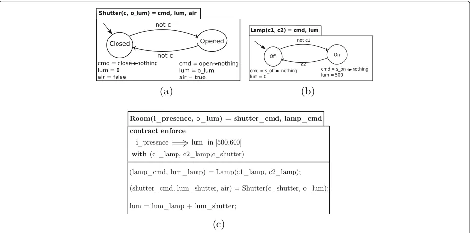
Let us consider as an example, in the context of building automation, a room equipped with a shutter and a lamp. To model this room, two parameters (luminosity and air) are first considered. Then, two automata are designed to model a shutter and a lamp.
Figure 5a presents the automaton that models a shut-ter. This automaton is contained in a H/BZR node that has two input flows (c,o_lum) and three output flows (cmd,lum,air). The automaton has two states (Closed, Opened) and two transitions. Each state is associated to three equations to produce the command of the shutter (cmd) and specify its effects on the environment (lum, air). In the state Closed, the command is equal to close(resp.nothing) if this state is (resp. not) newly activated. This prevents from continuously computing the commandclose while the shutter is already Closed. In this state, the shutter provides a luminosity equal to zero (lum = 0) and does not allow outdoor air to pass (air= false). In the stateOpened, the shutter provides a luminosity equal to the outdoor luminosity (lum = o_lum) and allows outdoor air to pass (air= true). The transitions going from a given state to a different one are associated to not c. This allows to open or close the shutter only when necessary. Figure 5b presents the lamp automaton. This automaton is the same than the one presented in Fig. 3.
4.1.2 Defining the target objectives and the controllable variables
Developers design a main H/BZR node that instantiates the automata modelling the devices and has a contract part. Then, developers define in the contract, the target objectives and the controllable variables.
Defining the objectives Developers specify the values that the considered environment parameters must take. These values may depend on data collected from the environment. This is done using variables and operators. Variables are used to refer to the collected data and also to the environment parameters. Operators, for instance,⇒ (logical implication) and∧(and) are used to express the relations between the variables. Examples of objectives for a room are:
1. presence⇒luminosity in [500,600] lux; 2. presence⇒noise < 80 dB;
3. presence∧temperature < 17 °C⇒heat; 4. presence∧CO2> 800 ppm⇒ventilation.
The first objective means that if a presence is detected, in the room, the luminosity must be between 500 and 600 lux. The second objective means that if a presence is detected, the noise level must be lower than 80 dB. The third objective (resp. the fourth objective) means that if a presence is detected and the temperature is below 17 °C (resp. the CO2 is above 800 ppm), the room must be heated (resp. ventilated). The devices required to reach the objectives and the actions to perform on them will be decided by thestep function. For instance, the first
objective can be reached by switching on the lamp or opening the shutter. The second action may be preferred for energy savings.
Defining the controllable variables Developers first analyse the input flows of the nodes that contain the automata modelling the devices. The aim is to identify the input flows that are controllable (their values are not given by the monitoring). Then, developers declare the identi-fied input flows, in the contract part of the main H/BZR node, as controllable variables. For instance, in the lamp automaton, presented in Fig. 5b, the input flowsc1and c2are controllable variables. In the shutter automaton, presented in Fig. 5a, the input flow c is a controllable variable. The input flowo_lumrepresents the value mea-sured by an outdoor luminosity sensor and hence it is uncontrollable.
Developers can use the declaration order of the control-lable variables to express preference between the transi-tions of the different automata. A transitionT1associated not c1is preferred to another transitionT2associated tonot c2if isc1is declared afterc2.
4.1.3 Example of H/BZR program for a room
Let us consider again the room, equipped with a shutter and a lamp. The objective to achieve is to maintain the luminosity between 500 and 600 lux when a presence is detected while minimising the energy consumption (i.e., prefer natural lighting to artificial lighting).
The H/BZR program defined for this room is presented in Fig. 5. It consists of three nodes. The first two nodes respectively contain the shutter and the lamp automata (Fig. 5a and b). The third node, presented in Fig. 5c, is the main node. It has two input flows (i_presence
ando_lum) and two output flows (shutter_cmdand
lamp_cmd). The input flows respectively represent the values measured by the room indoor presence sensor and outdoor luminosity sensor. The output flows respectively correspond to the commands to send to the shutter and to the lamp. This node defines acontracttoenforcethe target objective, through DCS,withthe controllable vari-ablesc1_lamp,c2_lampandc_shutter. These con-trollable variables are respectively related to the lamp and the shutter. The luminosity objective is expressed as
fol-lows: i_presence ⇒ lum in [500,600] where
lum is equal to the sum of the luminosity provided by the shutter and the lamp. The controllable of the shutter is declared after those of the lamp to specify that natural lighting is preferred to artificial lighting.
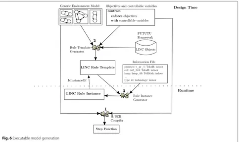
4.1.4 Executable model generation
Figure 6 shows how from the generic environment model, the target objectives and the controllable variables (i.e., a H/BZR program designed by developers) are generated the following elements:
1. Astepfunction; 2. A LINC rule template;
3. An instance of the LINC rule template.
At runtime, the LINC rule instance invokes the step function each time a relevant event occurs. When invoked, the step computes and returns appro-priate commands that will be executed by the rule instance.
Step generation The step is generated through the compilation of the H/BZR program designed by develop-ers. For instance, the compilation of the H/BZR program presented in Fig. 5 generates astep.
LINC execution rule template generation The execu-tion rule template is generated from the H/BZR program and the objects of the PUTUTU framework. This rule template collects the inputs of the main H/BZR node, invokes thestepfunction with the collected inputs and sends the computed commands (outputs of the main H/BZR node). The precondition of the rule template con-sists of a set ofrdoperations: onerdfor each input of the main H/BZR node and one rdto invoke thestep. The performance of the rule template consists of a sequence of two transactions. The first transaction consists of a set ofrdoperations to verify if the collected inputs have not changed and a set ofputoperations to send the computed commands and update the knowledge. Oneputis gener-ated for each output of the main H/BZR node and oneput is generated to update the knowledge. The second trans-action consists of a set of rdoperations to verify if the collected inputs did not change, one rd to verify if the knowledge did not change and oneputoperation to signal an actuator problem to the maintenance team. In the sec-ond transaction, the fact that the collected inputs are still the same and the knowledge did not change means that the first transaction aborted when performing an action on an actuator (it is faulty or unreachable). Otherwise, the knowledge would be updated. Hence, the maintenance is informed if the inputs are the same and the knowledge did not change.
Fig. 6Executable model generation
value). Finally, the precondition invokes thestep func-tion (line 4) and stores the computedcommandsin the variablesshutter_cmdandlamp_cmd(line 5). These variables will be used in the first transaction of the perfor-mance.
The first transaction verifies if the sensors data did not change (lines 8, 9). Then, it sends the computed shutter command to a shutter actuator. This is done by applying a puton theActuatorsbag of a PUTUTU object. This trans-action also sends the computed lamp command to a lamp actuator (line 11) and updates the knowledge (line 12). If a command cannot be sent due to a problem on the shutter (resp. the lamp) actuator, theputat line 10 (resp. line 11) fails and the knowledge is not updated. This prevents from inconsistencies. To signal the shutter or the lamp problem, the second transaction, sends a SMS to the maintenance team.
LINC execution rule instance generation From the generated rule template, a rule instance is generated with the actual sensors and actuators. This is done using a file that contains information related to the considered envi-ronment devices (i.e., type, id, technology, location). To generate an instance of the execution rule template, the rule instance generator replaces:
• Inrd operation,Objectnameandidby the technology and the id of the corresponding sensor;
• Input operation,Objectnameandidby the technology and the id of the corresponding actuator.
Listing 3 presents the file that describes the devices of the room example. This file specifies that the room is equipped with aTelosBindoor presence sensor with an id equal topr1, aRFXCOMoutdoor luminosity sensor, an EnOceanlamp actuator and aKNXshutter actuator.
specific sensors, invokes the step and sends the com-puted commands to specific actuators.
4.2 Creating soft sensors
Developers can create soft sensors from physical sensors to aggregate the data collected from the environment, to transform them or to estimate other data. For that, they write specific LINC rules called monitoring rules. These rules do not involve actuators and cannot be conflicting. These rules rely on the abstraction layer which hides the devices heterogeneity. Developers can also write monitor-ing rules for other data sources (e.g., agenda) to transform data or estimate required data.
Listing 5 presents an example of monitoring rule tem-plate. This rule template creates a soft presence sen-sor from a physical CO2 sensor. The precondition of this rule first reads in the variable co2_id_val, the value measured by a CO2 sensor. Then, the precondi-tion invokes a funcprecondi-tion (i.e.,pres_from_co2) with the variableco2_id_valas parameter to estimate if a pres-ence is detected or not. The result is stored in the vari-able pres_val. The performance inserts the resource (pres_id, pres_val)in theSensorsbag of the Soft-Sensors LINC object. This specifies that a presence has been detected or not by the soft presence sensor with the idpres_id. This monitoring rule is triggered each time a new CO2value is produced.
Once designed, a monitoring rule template is instan-tiated for a specific environment and the created soft sensor is added in this environment information file. Soft sensors and physical sensors are handled similarly when instantiating thestepexecution rule template.
4.3 Creating soft actuators
Developers can create soft actuators to allow some com-puted commands to be sent to more than one actuator. A
soft actuator groups several actuators, that have different ids and possibly different communication technologies, as one actuator. When creating a soft actuator, developers specify the number of actuators that must perform the action corresponding to the command (e.g., three lamps must be switched on).
When used in a rule, a soft actuator is seen as any other actuator: aputis done on itsActuatorsbag. When applied, the put sends the specified command to all the physi-cal actuators that are associated to the soft actuator. The putsucceeds if the action corresponding to the command can be performed by the specified number of actuators. Otherwise, theputfails.
Creating a soft actuator consists first in creating a spe-cific PUTUTU object that encapsulates one or several technologies. This is straightforward and is done by inher-iting from the existing PUTUTU objects that encapsu-late the technologies of the target physical actuators. By default, the operation put(id,command) on a PUTUTU objectActuatorsbag sends the command, given as param-eter, to only one actuator. Therefore, it is required to modify the behaviour of the put operation, on the cre-ated object Actuatorsbag, to send the command to the required number of actuators.
Once defined, a soft actuator is added in the environ-ment information file and will be used by the rule that invokes thestep, as if it were a physical actuator.
4.4 Dealing with changing objectives
Controlling smart environment devices requires to deal with changing objectives. The reason is that a realistic environment can have different configurations with differ-ent objectives (e.g., working time and holidays in a build-ing). This is done by first designing a controller for each configuration. Then, switching between the controllers, at runtime, as illustrated in Fig. 7.
Let us consider a system and a set of controllers, designed in H/BZR, to achieve different objectives. To achieve its objectives, each controller accepts specific states of the system and rejects the other states (i.e., those that can violate its objectives). A state rejected by a given controller is not allowed to be reached when this controller is activated. Hence, switching an activated controller (e.g.,Ct1) for another controller (e.g.,Ct2) is possible only if the current state of the system (accepted byCt1) is accepted by the controllerCt2.
Switching controllers is not an easy task in general because it is not straightforward to decide if a given state is accepted by a controller. Indeed, a state is accepted by a controller if it:
• Belongs to the state space (set of known states) of the controller;
Fig. 7Controller reconfiguration through the framework
• Does not lead, through one or several uncontrollable transitions, to a state violating an objective.
However, in the context of smart environments, partic-ular solutions can be performed to enable the switch of controllers. An example of solution is to design the differ-ent controllers in such a way that they all have the same initial state. This allows to switch them when this state is reached. For instance, a building may have a night state where it is not occupied, completely closed, not heated and not ventilated. This state can be use as the initial state of all the building controllers. Another possible solution is to try to synthesise the target controller from the current state of the activated controller. If the controller synthesis succeeds and the current state has not changed, the switch can be done.
To enable the reconfiguration, the execution rule of each controller is associated to a resource to be activated or deactivated. For this, a LINC bag called CurConfigurationis first created. This bag contains one resource indicating the current configuration of the considered environment. Then, each execution rule is modified to enable its activation and deactivation.
To illustrate the reconfiguration, let us consider an example in the context of building automation. One can design two controllers (with the same initial state), for different configurations of a building (e.g., working time and holidays). Then, the execution rules of the controllers are modified as shown in Listing 6 for the working time execution rule. A rd on the configuration of the con-troller is added in the beginning of the precondition and in the beginning of each transaction. This ensures that an execution rule is triggered only if the resource corresponding to its controller configuration is present in the bagCurConfiguration.
Hence, switching a controller for another one consists in removing the resource of CurConfigurationand adding the appropriate resource. This is done by writing a switching rule. For instance, Listing 7 presents an exam-ple of LINC rule that switches the working time controller for the holidays one when the eventholidays_start is triggered and the night state of the building is reached. The performance of the rule consumes the event resource and the current configuration resource and inserts the
Holidaysresource.
4.5 Deployment
After the design phase, the framework generates a set of LINC rules and objects that have to be deployed. The objects consist of one HBZR object (used for the step and several PUTUTU objects, one for each sen-sors/actuators technology used in the target environment. Each PUTUTU object (e.g.,Plugwise) must be deployed on a computing device that has the appropriate dongle (e.g., plugwise dongle). TheHBZRobject does not require a dongle and can be deployed on any computing device. Once the deployment is performed, the control loop starts and the controller will be invoked when a relevant event occurs in the environment.
4.6 Handling a high number of devices
When the number of devices is high, using one single loop may become a bottleneck. First, the synthesis of the loop controller can take a lot of time or not succeed due to computing resource limitations. Second, the execution rule reads several data in its precondition part. This can lead to runtime performance degradation.
In this case, the devices can be partitioned in several sets. Then, one loop is used for each set, as illustrated in Fig. 8. In this context, each set of devices has a con-troller. If the devices sets are independent, nothing more is required. Otherwise their controllers must be coordi-nated, using priorities on their actions on shared devices. In this case, an output value of a given controller can be an uncontrollable input for another one.
The coordination of controllers is currently done in LINC. The execution rule of a controller can insert a value in specific bags or read a value inserted by another controller execution rule. The coordination could also be done in H/BZR, by exploiting the potential of modular discrete controller synthesis, as done in [34].
5 Case study
This section illustrates the proposed framework through a case study taken in the field of building automation. The aim is to manage the devices of a building in order to
achieve a set of objectives. The building is first described. Then, its devices are managed and a demonstrator is pre-sented to show that the framework was able to reliably achieve the target objectives. Then, the management cost is evaluated to show the scalability of our approach. Finally the case study is discussed to compare the framework to related work approaches.
5.1 Building description
The considered building consists of ten small offices and twelve big offices, that are separated. A small office con-sists of a room that contains: a window, a shutter, a door, a lamp, a reversible air-conditioner (RAC), a mechanical ventilation (MV), a temperature sensor and a CO2 sen-sor. A big office has an additional lamp, window, shutter and temperature sensor compared to a small office. A big office also has a presence sensor. Several sensors are installed outside the building to enquire outdoor condi-tions (i.e., luminosity, CO2, noise, temperature, pollen). Noise sensors are also installed in the corridors. The actuators and sensors of the building use different com-munication technologies (e.g., EnOcean, TelosB). Each room has a file that describes its devices (id, type, tech-nology and location). Information about the meetings (e.g., day, time, features) that will be held in each room can be obtained through a specific agenda. The devices of the rooms must be managed to achieve the following objectives:
• For comfort, when a presence is detected, the luminosity must be between 500 and 600 lux and the noise level must be lower than 80 dB;
• For air quality, when a presence is detected and the CO2exceeds 800 ppm, the room must be ventilated.
It must not be be polluted by pollen or outdoor CO2
and must be quickly ventilated between meetings separated by less than 30 minutes;
• For comfort, when a presence is detected and the temperature is below 17 °C (resp. above 27 °C), the room must be heated (resp. cooled);
• For confidentiality, the room must be completely closed during a confidential meeting;
• For energy savings, natural lighting, ventilation, heating and cooling are preferred to artificial lighting, ventilation, heating and cooling.
5.2 Devices management using the proposed framework To achieve the objectives in the rooms, developers have to design a H/BZR program, from which a step func-tion and an execufunc-tion rule template will be generated. Then, developers have to write two monitoring rule tem-plates to respectively estimate a presence in a small room (not equipped with a presence sensor) and to compute a temperature average in a big room (has two temperature sensors). Developers also have to write a monitoring rule template to know from an agenda, if there is a meeting or not and if a meeting will be held in less than 30 min, after a previous meeting. Finally, the rule templates are instantiated in each room.
5.2.1 Designing a H/BZR program
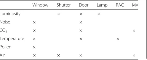
This requires to design a generic model of a room. For this, a set of environment parameters are first considered (i.e., luminosity, noise, CO2, temperature, pollen and air). Then, the effects of the devices on these parameters are specified. As presented in Table 1:
• A window:affects five parameters (noise, CO2, air,
temperature, pollen). When the window is opened, it introduces the outdoor noise in the room. It can ventilate, heat or cool the room, depending on the outdoor conditions. It can pollute the room by introducing pollen or outdoor CO2;
• A shutter:affects two parameters (luminosity, air). When the shutter is closed, it provides a luminosity equal to zero and stops the outdoor air;
• A door:affects five parameters (luminosity, noise, CO2, temperature, air). When the door is opened, it
lights the room (if the corridor lamps are on) and introduces the corridor noise;
• A lamp:affects one parameter (luminosity). It provides 500 lux when it is on and 0 when off;
• A RAC:affects the temperature of a room;
• A MV:affects the CO2and the air.
Table 1Environment parameters and devices
Window Shutter Door Lamp RAC MV
Luminosity × × ×
Noise × ×
CO2 × × ×
Temperature × × ×
Pollen ×
Air × × × ×
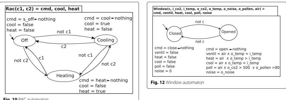
A generic room model is obtained by designing automata that describe the behaviours of a window, a shut-ter, a door, a lamp, a RAC and a MV. All the automata have an output flow that is the command to send to the mod-elled actuator. This command is equal tonothingwhen the actuator should not receive a command. For instance, to switch off a lamp, the command is equal to s_off when the lamp is on andnothingas long as it remains off. The lamp and shutter automata are those presented in Fig. 5.
Figure 9 presents the automaton that describes a door. This automaton has two states and two transitions. Each state is associated to two equations to produce the com-mand of the door and also specify its effect on a room noise level. For instance, at the stateClosed, the door affects the noise level with a value equal to zero. The effects of the door on the other parameters (i.e., air, CO2, temperature, luminosity) are not considered because the corresponding sensors do not exist in the corridor and their values cannot be obtained. The transitions that go from a state to a different one are associated tonot c. This allows to open or close the door only when necessary. Figure 10 presents the automaton that describes the behaviour of a reversible air-conditioner (RAC). This automaton has three states and six transitions. Each state is associated to three equations to produce the command of the RAC and also specify its effects on the room. For instance, at the state Off, the RAC does not cool nor heat the room. This automaton is contained in a node that has two input flowsc1andc2. The reason is that, at each state, three transitions can be triggered (i.e., two transitions that leaves the state and one that allows to stay). To associate a different boolean expression to each of the three transitions of a state, at least two variables are needed. For instance, when the stateOffis activated, if the input flowc1isfalse, the RAC automaton goes to the stateCooling. Ifc2isfalse, it goes to the state Heating. If both c1 and c2 are true, it remains at the state Off. Finally, if bothc1andc2arefalse, at the same instant, the transition that was first declared is
Fig. 10RAC automaton
chosen. Associatingnot c1andnot c2(resp.c1and c2) to the transitions that leave (resp. come to) the state Offmeans that it is preferred to maintain the RACOff for energy savings.
Figure 11 presents the automaton that describes the behaviour of a mechanical ventilation (MV). This automa-ton has three states. Each state is associated to three equations to produce the command of the MV and spec-ify its effect on the CO2 concentration of a room. For instance, at the state Off, the MV does not ventilate the room. At Mode1, the MV ventilates the room but not quickly, as done inMode2. The transitions that leave (resp. come to) the state Offare associated tonot c1 andnot c2(resp.c1andc2) to express that it is prefer-able to not use the MV.
Figure 12 presents the automaton that describes the behaviour of a window. This automaton has two states. Each state is associated to five variables to specify the effects of the window on different parameters of a room. At the stateClosed, the window does not ventilate, heat,
Fig. 11MV automaton
Fig. 12Window automaton
cool, pollute nor introduce outdoor noise in a room. At the stateOpened, the window can heat, cool, ventilate, pol-lute or affect the noise level of a room, depending on the indoor and the outdoor conditions. The transitions that lead to a different state are associated tonot cto spec-ify that the window should be opened or closed only when necessary.
Once the devices modelled as automata, the H/BZR node presented in Fig. 13 is designed. This node defines one instance of each device automaton and has a con-tract. The contract defines the target objectives and a set of controllable variables. These variables are the input flows associated to automata transitions with a value not given by the monitoring. The energy savings objective (i.e., natural lighting, heating, ventilation and cooling are pre-ferred) is expressed by declaring the controllable variables of the shutter and the window after those of the lamp, the RAC and the MV. This H/BZR node represents a room automaton. It takes as input sensor values and meetings information and returns the commands to send to the actuators.
Once defined, the H/BZR program (set of defined nodes) was compiled to generate a step function. The H/BZR program was also used to generate an execution rule template that was instantiated for each room.
5.2.2 Execution rule template generation
Fig. 13Room automaton
transaction verifies if the sensor values did not change. Then, it applies sixputoperations on theActuatorsbags of six PUTUTU objects, referred as Objectname, to send the computed command to the actuators. Finally, it updates the room generic model (changes the room automaton state). The second transaction sends a SMS to the maintenance if a command cannot be sent (e.g., com-munication error, actuator failure). The execution rule template was instantiated in each room of the building. For the big rooms, equipped with two lamps, two win-dows, two shutters, one RAC, one door and one MV, some computed commands (i.e., lamp_cmd, window_cmd, shutter_cmd) are sent to two actuators.
5.2.3 Monitoring rules design
A monitoring rule template is designed to estimate a pres-ence from the value measured by a CO2sensor, in a small room. This rule template is the one presented in Listing 5. Another monitoring rule template is designed to compute a temperature average in a big room (is equipped with two temperature sensors). This rule is presented in Listing 8. The precondition of this rule first reads two temperature values measured by two different sensors. Then, it uses a function to compute the average and stores it in the vari-abletemp_aver. The performance of this rule stores the computed average in theSensorsbag of theSoftSensors object. A monitoring rule template is designed to obtain
relevant meeting information from a room agenda. This rule returns a resource that specifies if there is a meeting, if it is confidential and if meeting will be started in less than 30 min, after a previous meeting.
The designed monitoring rule templates were instanti-ated in specific rooms. This was done by replacing, in each operation,Objectname and id, respectively, with the technology and id of the corresponding sensor.
5.3 Demonstrator with concrete devices
To illustrate the framework, a demonstrator was built. The aim is to achieve, in a room, two objectives:
presence ⇒ luminosity in [500,600] lux,
confidential meeting ⇒ room completely
closed. The demonstrator, as shown in Fig. 14, consists of:
• A Plugwise circle[35]: Is a plug used to
Fig. 14Demonstrator
by applying the operationput(id,command) on the Actuators bag of a Plugwise PUTUTU object.
• An EnOcean switch[36]: Is used as a presence sensor. The switch has a button that can be pressed to emulate a presence. The value of the switch (presence detected or not) is obtained by applying the operationrd(id, value) on the Sensors bag of the EnOcean PUTUTU object.
• A graphical interface: Is used to emulate a shutter. A bag, contained in an object (Shutter), is created to send a command to the shutter. The insertion of a resource in this bag, shows the corresponding action (open, close) on the interface.
• A Raspberry Pi:Is used to deploy the objects and the execution rule. It is connected to the switch and to the circle through two dongles.
Two bags (i.e., OutdoorLuminosity andAgenda) contained in an object (Room) were created to respectively emulate an outdoor luminosity sensor and an agenda for meetings. These bags were manually filled. The step function generated for the building was used.
Figure 15 presents the MIADIE-K loop that was set up for the demonstrator. This loop is an instantiation of the the generic loop presented in Fig. 1. Data are first collected through the abstraction layer: theRoomobject (outdoor luminosity and confidential meeting) and the EnOceanobject (presence detected by the switch). Then, the collected data are used to invoke thestepfunction that, based on the automata of the shutter and the lamp, computes and returns the commands that achieve the objectives without conflict. Finally, the computed com-mands are sent to the devices and the states of the two automata are changed.
Several scenarios were performed to validate the demonstrator. Some scenarios were with a potential con-flict (i.e. presence detected, outdoor luminosity in [500, 600] lux and confidential meeting held), communication errors or actuator failure (e.g., circle unplugged). In all cases, there was no conflict and no inconsistency. Three examples of scenarios are:
• First scenario:The button of the switch was pressed to emulate a presence and the outdoor luminosity was set to 500 lux by inserting the resource ("500")in the bagOutdoorLuminosity. A confidential meeting was also emulated by inserting the resource("confidentialMeeting")in the bagAgenda. This switched on the lamp and closed the shutter. The conflict which consists in opening the shutter for daylight and closing it at the same instant for confidentiality was avoided.
• Second Scenario:It was performed just after the first scenario. The presence was still detected, the outdoor luminosity was equal to 500 lux, the shutter was closed and the lamp was on. In this context, the end of the confidential meeting was emulated by removing the resource("confidentialMeeting")from the bagAgendaand inserting the new resource ("notConfidentialMeeting"). This opened the shutter and switched off the lamp to save energy.
• Third Scenario: It was performed after the second scenario. The presence was still detected, the lamp was off and the shutter was opened. In this context, the outdoor luminosity was set to 700 lux. In addition, a failure was emulated on the lamp (i.e., the circle was unplugged). In this case, the controller decided to close the shutter and switch on the lamp to maintain the luminosity between 500 and 600 lux. Since there was a problem on the lamp, nothing was done and a SMS was sent to the maintenance to signal the problem. Hence, the inconsistency which consists in wrongly assuming that the lamp was switched on was avoided.
5.4 Evaluation of the devices management cost
This section evaluates the design cost and the runtime cost of the proposed devices management approach.
5.4.1 Design cost evaluation
When using the proposed framework, developers describe the actuators and define the target objectives. They do not have to manually specify the desired behaviour of the considered smart environment. This is enabled by the generation of a controller, through Dis-crete Controller Synthesis (DCS). For instance, in the case study, one controller was generated using six automata with a total of 65 variables, modelling a lamp, a shutter, a window, a door, a RAC and a MV. The synthesis of the controller took 1.4 s, on a computer with a processor Intel i7 (3.4 GHZ) and 16 GB of RAM.
Fig. 15Demonstrator devices management
variables and the uncontrollable variables. The Table 2 shows the synthesis time of a controller for different rooms with different number of devices that do not have the same behaviour. The devices of each room are described using automata associated to variables. The Table shows that the synthesis time grows exponentially with the number of variables of the model.
When the number of variables is high, the synthesis of the controller can take a lot of time or not succeed to due limitations of CPU and/or RAM. In our approach, the generic environment model allows to deal with this limita-tion. All the devices that have the same behaviour are seen as one device and hence they are modelled using one sin-gle automaton and the associated variables. This improves the scalability by reducing the controller synthesis time. However, this is limiting for a high number of devices that have different behaviours, several automata must be used. In this case, the devices are managed by designing several autonomic loops, as explained in the Section 5.4.3.
Table 2Design costs comparison
Considered rooms Synthesis time
R1 (6 devices/65 variables) 1.4 s
R2 (12 devices/101 variables) 31 s
R3 (18 devices/137 variables) 797 s
R4 (24 devices/173 variables) 4888 s
R9 (48 devices/353variables) 10920 s
5.4.2 Runtime cost evaluation
At runtime, the generated execution rule reads data from all sensors and other sources and invokes thestep func-tion to compute the commands. Thestepis similar to a set of if then else and has a runtime cost that is low. Hence, the runtime cost of the execution rule depends on the data it reads in its precondition part.
The fact that the execution rule reads data from all sen-sors and other sources leads to a runtime cost that is not negligible, when the number of devices is high. The rea-son is that the middleware LINC is used to design reactive rules. To not miss an event and to react as soon as it occurs, a rule is executed by building an inference tree from the data read in its precondition. Hence, the more a rule reads data, the bigger is the inference tree. This slows down the rule execution.
However, to avoid conflicts and ensure reliability, it is necessary to read data from all sensors and have a global view of the environment. For instance, opening a window to cool a room requires not only data from temperature sensors but also outdoor noise, CO2and pollen sensors to not violate other target objectives.
5.4.3 Design cost and runtime cost improvement
(e.g., independent) and the structure of the considered smart environment (e.g., a building is composed of floors that consist of rooms).
Managing the devices by designing multiple loops improves the scalability of our approach, by reducing the design cost. Indeed, the controller synthesis is done for each devices set (not in all the devices) and can be performed modularly [34]. This also improves the speci-fication by allowing developers, when providing the envi-ronment model, to consider sets of limited devices instead of all the devices. Finally, this allows for the distribution of the loops and improves the execution cost. More details on how smart environment devices are managed using multiple loops can be found in [37].
5.5 Discussion about the case study and qualitative comparison with related work approaches
The proposed framework allows developers to generate an executable model for the management of smart environ-ment devices. To enable the executable model generation, developers provide a model of the considered environ-ment and the target objective. The environenviron-ment model is defined by specifying for each device, its states, its state transitions and its effects on the environment parame-ters. The objectives are defined by specifying the values the environment parameters must take. From the envi-ronment model and the objectives are generated a con-troller and an execution rule. At runtime, the execution rule collects data from the environment and invokes the controller that makes appropriate decisions to reliably achieve the objectives. In the followings, our approach is compared with the related work approaches to show its advantages.
5.5.1 Comparison with rule based approaches
In rule based approaches (e.g., [5, 6]), developers define a set of rules to specify the actions to perform when events occur. These approaches are intuitive for the management of smart environment devices [38]. However, developers have to manually consider all the possible cases to define a set of complete rules. This prevents the system from being in a state where no action can be performed because the corresponding rules are not defined. For a large system, manually considering all the possible cases is tedious.
In our approach, all the possible cases are computed through discrete controller synthesis and a controller that decides the actions to perform depending on the events that occur is generated. This allows developers to not manually consider all the cases and this ensures that there is no conflicts and violations of objectives.
5.5.2 Comparison with model checking based approaches
In model checking based approaches (e.g., [3, 4]), developers first model the entities of the considered
system and how they interact to achieve the target objectives (i.e., decide the actions to perform when events occur). Then, developers define a set of prop-erties and the model checker verify if the propprop-erties are satisfied by the given model. If a property is not satisfied, the model is modified and verified again. When the properties are satisfied, developers imple-ment the corresponding executable model, for instance by generating rules from the verified model, as done in [13].
Verifying the model prevents from conflicts and objec-tives violations. This ensures the reliability of the smart environment. The model verification relies on the state space exploration techniques and is, similarly to our approach, exponential in the number of variables of the model. The execution of the executable model is also the same in both approaches. The advantages of our approach is that developers do not have to model how the devices interact to achieve the objectives (i.e., decision making) and do not need to modify the model when a property is not satisfied. Developers just describe each devices (states, transitions, effects on the environment) and the objec-tives. The decisions are reliably made by a controller that is generated.
6 Related work
In [2–4, 13, 14, 39], the authors propose model check-ing based approaches for reliable smart environments. These approaches consist in first modelling the desired behaviour of the considered smart environment (i.e., the behaviour of the devices and how they interact to achieve the target objectives). Then, verifying if a set of prop-erties, expressed in temporal logics, are valid in the designed model, using a model checker. In the oppo-site, our approach does not require to model the desired behaviour or verify properties. The properties are, auto-matically, enforced on a model that describes the features of each device (i.e., effects on the environment, states and transitions). For this reason, our approach is more con-venient than those based on model checking. It allows to declaratively obtain the desired behaviour of the consid-ered smart environment. The advantage of model check-ing based approaches is that several methods have been proposed for the reduction of the verification cost. To benefit from these methods, for a large system, one can combine model checking with our approach. In this case, the considered system is first divided into several sub-systems. Then, the subsystems with a desired behaviour that can (resp. cannot) be easily specified manually are designed using a model checking based approach (resp. our approach).
rules (e.g., conflicts, circularities, constraints violations, redundancy). Then, they propose methods to detect (e.g., pairwise comparison, model checking) and solve (e.g., pri-ority) the considered errors. These approaches do not enable the detection of implicit errors. Indeed, they do not consider the effects of the rules on the environment. Our approach prevents from both implicit conflicts and constraint violations, by considering the devices effects on the environment.
In [11, 12, 40], the authors propose environment aware approaches for the reliable smart environments. These approaches enable the detection of implicit conflicts and/or objectives violations, by considering the effects of devices. However, using these approaches require to man-ually solve the detected conflicts and objectives violations. In addition, they do not consider the inconsistencies that are due to communication errors and hardware failures, as done in our approach.
In [32, 41], the authors propose an approach that han-dle inconsistencies. This approach consists in verifying if the actual effect of an action, on an actuator, is equal to its expected effect, using data from sensors or other sources. An inconsistency is assumed if the actual effect of an action is different from its expected effect. In this case, the action is performed again using an alterna-tive actuator. The limitation of this approach is that it can take a lot of time to detect an inconsistency, for instance when the effect of the action is not instan-taneous (e.g., temperature variation). In our approach, when performing an action, the fact that the actuator is faulty or unreachable due to a communication error is detected. This prevents from taking a lot of time to detect that the action was not performed. However, an actua-tor can become faulty after the action is done. Such a failure is not detected by our approach. A possible solu-tion to detect such a failure is to verify the actual effects of actions, using data from sensors. For this reason, the approach proposed in [32, 41] is complementary to our approach.
In [42], the authors propose an approach that pre-vents from implicit conflicts among a set of ECA rules and enables the detection inconsistencies. For this, each rule specifies its post-condition (expected effect). Post-conditions are used to detect conflicts and inconsisten-cies. A conflict is detected at design time when the same event triggers rules with contradictory post-conditions or at runtime when such rules are triggered by different events. Conflicts detected at compilation time are solved by users and those detected at runtime are solved by a set of resolution rules. An inconsistency occurs if the actual effect of a rule is different from its post-condition. In this case, a failure event is raised to trigger alternative rules (if they are defined). This approach is limited because users have to solve conflicts and also it takes time to detect an
inconsistency, when the effect of the involved rule is not instantaneous.
In [43], the authors propose an approach that enables the detection of errors (conflicts and objectives viola-tions) among a set of rules. This approach also enables the detection of inconsistencies by verifying the actions actual effects. In a more recent work [44], the authors consider environment dependencies for the detection of implicit errors. However, using this approach requires to solve the detected errors. Moreover, the fact that an actua-tor is faulty is not detected when performing an action on it, as done in our approach, but after a certain time when the expected effect is not observed.
7 Conclusion
This paper has proposed a framework for reliable and environment aware management of smart environment devices. This framework enables the declarative manage-ment of devices, hides their heterogeneity, prevents from inconsistencies (due to communication errors or actu-ators failure), and conflicting decisions including those caused by environment dependencies. This is done fol-lowing the autonomic computing principles. First, an abstraction layer is used to collect data from the environ-ment. Then, based on the data and knowledge about the environment, a generated controller computes appropri-ate commands that allow to reach the target objectives without conflict. Finally, a transactional execution mecha-nism is used to atomically send the computed commands to the actuators and update the knowledge to prevent from inconsistencies.
In current status, the proposed framework has two main limitations. First, developers have to describe the behaviours of actuators and specify their effects on the environment. Hence, the reliability of the devices manage-ment depends on the accuracy of the descriptions given by developers. Second, when performing an action on a actuator that is not a soft actuator, if the action cannot be performed (e.g., due to a communication error), a SMS is sent to the maintenance team and nothing else is done meaning that the controller stops until the problem is solved by the maintenance.