An Improved Channel Estimation Algorithm
Based on Cubic Convolution Interpolation for
LOWPM System
Ge-wei Tan
School of information science and engineering, Huaqiao University, Xiamen, China Email: [email protected]
Guang-wu Pan and Wei Lin
School of information science and engineering, Huaqiao University, Xiamen, China Email: [email protected], [email protected]
Abstract—Lifting scheme based orthogonal wavelet packet multiplexing (LOWPM) system can increase the computation efficiency and save storage space. By using the orthogonality of the translational wavelet functions, LOWPM system efficiently avoids inter-symbol interference (ISI) and inter-channel interference (ICI). Compared with the orthogonal frequency division multiplexing (OFDM) system, LOWPM system has higher spectrum efficiency and anti-jamming performance. However, in frequency-selective fast-fading channel, the performance of system is still not ideal. In order to implement high bit rate transmission, channel estimation technique is needed to combat noise of the channel. This paper presents an improved channel estimation algorithm in which the cubic convolution interpolation is applied to the pilot based linear minimum mean square error (LMMSE) channel estimation algorithm so as to get higher estimation accuracy. Simulation results show that, the algorithm can effectively improve the performance of the LOWPM system.
Index Terms—orthogonal wavelet packet multiplexing, lifting scheme, channel estimation, cubic convolution interpolation, linear minimum mean square error estimation
I. INTRODUCTION
OFDM is the key technology of the next generation of mobile communication. With serial to parallel conversion, OFDM technology turns high rate broadband signals into parallel low rate narrowband signals, so increases the length of each symbol, and eliminates the impact of multipath propagation effectively[1]. In OFDM system signals must be inserted protect interval and cyclic prefix in order to eliminate ISI and ICI, which indicates the improving of transmission performance at the expense of transmission rate.In the field of wireless communication, frequency resource increasingly tense, this is a problem to
be considered. Wavelet packet transform based orthogonal wavelet packet multiplexing (OWPM) system has higher spectrum efficiency because it does not need cyclic prefix[2][3][4]. In addition, the wavelet transform has time-frequency local property, the power difference of its main-lobe and vice-lobe is 45dB, so it can well suppress sidelobe without adding the window, thereby reducing the effect of inter symbol interference[5].
The theory of lifting wavelet transform is proposed by Swedens and Daubechies in the mid 90’s, which is a kind of simple and general wavelet construction scheme that does not depend on Fourier transform[6]. It has the advantages of simple structure, low computational complexity, in situ operation and save storage space. Compared with Mallat algorithm, the lifting scheme is an efficient method to implement wavelet transform[7]. Therefore, lifting scheme based orthogonal wavelet packet multiplexing system has practical significance for improving the transmission rate and the operational efficiency.
Accurate channel estimation can greatly improve the performance of system in wireless transmission. Channel estimation attempts to track the channel response by periodically sending known pilot symbols. For deriving a complete characterization of the channel. Channel response is first estimated on the pilots and then interpolated between pilots to calculate the response over the data carriers[8,9,10]. Popularly interpolation algorithm is more complexing, the improving of system performance is more obviously[11,12]. Jointly considering estimation accuracy and system complexity, cubic convolution interpolation algorithm is proposed in this paper, which is combined with the linear minimum mean square error channel estimation algorithm to improve the performance of LOWPM system.
The paper is organized as follows. In Section II, the lifting scheme based orthogonal wavelet packet multiplexing system is described, lifting wavelet transform and the implementation of (9,7) lifting wavelet transform are discussed. Section III discusses
( )
x n
( )
d n
( )
r n
( )
s n
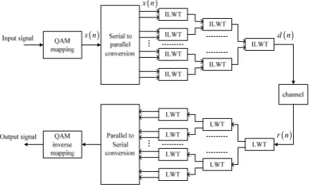
Figure 1. Lifting scheme based orthogonal wavelet packet multiplexing system.
symbol based LOWPM system and comb-type pilot arrangement, the estimation of pilot signals, and interpolation methods. Section IV presents the simulation results, which indicate the BER improvements. Section V concludes the paper.
II. LOWPMSYSTEM AND IMPLEMENTATION OF LIFTING
WAVELET TRANSFORM
A. Lifting Scheme Based Orthogonal Wavelet Packet Multiplexing System and Signal Mode
Using inverse lifting wavelet transform (ILWT) and lifting wavelet transform (LWT) to implement modulation and demodulation of multicarrier communication not only overcomes the weaknesses that OFDM system is very sensitive to frequency offset and phase noise, but also obtains high operational efficiency compared to Mallat algorithm. The system model is shown in Fig. 1.
In Fig.1, modulators are synthesis filter banks with multiple input and single output, and demodulators are analysis filter banks with single input and multiple output. Both of which can be achieved through multistage lifting, using lifting steps to replace the filter groups can implement lifting scheme based orthogonal wavelet packet multiplexing system.
In wavelet packet transform, family of wavelet packet functionsφl m, , 0, l≥ 1≤ ≤m 2l can be expressed as:
( )
( ) (
)
1,2 0 ,
l m l m
n
t h n t nT
φ+ =
∑
φ −( )
( ) (
)
1,2 1 0 ,
l m l m
n
t g n t nT
φ+ + =
∑
φ −where h n g n0
( ) ( )
, 0 are low-pass and high-pass filtercoefficient respectively. φl m, is wavelet packet function of
the lth layer and the mth node of wavelet packet decomposition, φ0,1 is the scale function φ , φ0,2 is the
mother wavelet function ψ, Tl =2lT0 is symbol duration
of the lth sub carrier.
The information bits are firstly grouped and mapped into MPSK or M-QAM. Then the serial data stream is transformed to M parallel lines, where M is the number of sub carriers which is dependent on channel state. So pilots can be inserted into the M lines of signals with particular pilot arrangement strategy, then the obtained M lines of signals can be modulated through ILWT. So signal of time domain to be transmitted can be calculated by the following equation:
( )
( )
( ) (
)
2
, ,
,
c
j f t
l m l m l
l m n
d t x n φ t nT e π
∈Γ
=
∑ ∑
− (1)( )
, l mx n represents the digital signal which modulates the
scale function φl m, at node( , )l m , which is also the data
stream at sending end after the pilots are inserted; Γ represents the collection of sequence
( )
l m, of wavelet packet functions. fcis carrier frequency.The orthogonality between sub carriers is expressed as, φl m,
(
t−j)
,φl m,(
t k−)
=δj k, , ,j k Z∈ (2)φl m,2
(
t− j)
φl m,2 +1(
t k−)
=δj k, , ,j k Z∈ (3)Eq. 2 indicates that wavelet packet functions are self orthogonal for integer translation, satisfying this condition can eliminate the inter symbol interference. Eq. 3 shows that the odd and even subscript wavelet packet function are orthogonal, satisfying this condition can eliminate the adjacent channel interference.
Transmitted signals will pass through multipath Rayleigh fading channel with additive noise. The received signal is given by:
( )
2 [ ]1
( ) c i D i ( )
N
j f f t
i i
i
r t a d t τ e π− τ+ w t
=
=
∑
− + (4)where N is the number of total path, ai is the amplitude
gain of each path, τi is delay of the th
i path relative to the
direct path, fDi is Doppler frequency shift of the
th
i
path[13], w t
( )
is the AWGN noise with zero mean andvariance of σ2.
At receiving end, the demodulation of information is implemented by wavelet packet decomposition. The recovered kth information at node
(
l m, ')
is( )
( )
', ' 1 , '
2 [ ]
, ' 2
, '
( ) ( )
( ) ( ) ( )
c i Di
l m l m l
N
j f f t
i i l m l
i
l m l
d k a d t t kT
a d t e t kT
w t t kT
π τ
φ
τ φ
φ
− +
=
= −
+ − −
+ −
∑
(5)where the first item is components of useful information, the second item as interferences caused by multipath and the third item as interferences generated by the Gauss noise. Thus Eq. 5 can be decomposed into three parts,
1 , , , ' 1 , '
( , )l m n l m( ) l m( l)l m( l) l m( )
A a x nφ t nT φ t kT a x k
∈Γ
=
∑ ∑
− − =2 [ ]
, , , '
2 ( , ) ( ) ( ) ( )
c i Di
N
j f f t
i l m l m i l l m l
i l m n
B a x nφ t τ nT e π− τ+ φ t kT
= ∈Γ
=
∑ ∑ ∑
− − −1
P U1 Pm Um Um Pm U1 P1
o
s
e
s c n1( ) c n( )
( )
d n ( )
s n
( )
1 d n
( ) s n
Figure 2. Implementation of lifting wavelet transform and inverse lifting wavelet transform.
α β γ δ
o
s
e
s c n( )
( )
d n
( )
s n
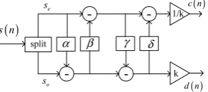
Figure 3. Constructure of (9,7) lifting wavelet transform.
When m m= ' , which shows interferences are
generated by the same sub channel of different paths; when m m≠ ', which indicates interferences are caused by different sub channel of different paths. Because of the orthogonality for integral translation of wavelet packet functions, if τi=kT k Zl, ∈ , interferences are zero; if the
conditions of integer times between τi and Tl can not be
met, due to the properties of compact support and time localization of wavelet packet functions, the cross-correlation between different wavelet packet function is small, so the ability of anti multipath of LOWPM system is strong.
Simplifying the influence of multipath Rayleigh channel and noise, the received signal can be expressed as
r t
( ) ( ) ( ) ( )
=d t ∗h t +w t (6) where h is the channel impulsive response. Using channel estimation technique to get the value of h, theemitted signal finally can be recovered.
B. Implementation of lifting Wavelet Transform
Lifting wavelet transform includes three steps that are split, predict and update, and the corresponding inverse transform comprises the inverse update, inverse prediction and merge. Any discrete wavelet transform of two channel filter groups with finite length can be decomposed into a series of simple lifting steps, so wavelet lifting algorithm can replace Mallat algorithm. It is possible to realize multistage filer groups using multiple lifting steps. Fig. 2 is the constructure of lifting algorithm and inverse lifting algorithm.
Split: input signal is split according to its element subscript, its even subscript elements constitute a collection, called even sequence se, sequence composed of odd subscript elements is so, this process is also called lazy wavelet transform.
Predict: the essence of this step is using the correlation of data to predict the odd sequence through even sequence, and prediction error is
d n1
( )
=s no( )
−P s n1⎡⎣ e( )
⎤⎦ (7)where, P1is the prediction operator. After the first lifting,
the prediction errors constitute the new odd sequences which are also called wavelet coefficient.
Update: updating even sequence through the prediction errors.
c n1
( )
=s ne( )
−U d n1⎡⎣ 1( )
⎤⎦ (8)where U1 is update operator. The updated results is
approximation of original signal, namely scale coefficient, the step which generates new even sequences is also called dual lifting. After several times of prediction and updating, finally gets the approximation coefficient c n
( )
and detail information d n
( )
of the original signal. Thekey of implementing of lifting algorithm is how to obtain the prediction operator and the update operator.
The reverse execution of above process and inverse the addition and subtraction can implement the inverse wavelet transform.
C. Signal Processing of LOWPM System
In the paper, LOWPM system uses Daubechies (9,7) lifting wavelet to realize modulation and demodulation of multicarrier signal, which includes two step prediction and two step updating. The constructure of (9,7) lifting wavelet transform is shown in figure 3.
In Fig. 3, the prediction operators and updating operators are: α= −1 586134342. , β= −0.052980118,
0.882911075
γ= , δ=0.443506852 and the proportion
coefficient is k=1.149604398. The implementation steps
of lifting algorithm as follow:
1. Using even sequence to predicting odd sequence, and gaining new odd sequence which is also the prediction error.
(
2 1) (
2 1)
( ) (
2 2 2)
d n+ =s n+ +α⎡⎣s n +s n+ ⎤⎦
2. Using the prediction error to update even sequence and obtaining new even sequence:
( ) ( )
2 2(
2 1) (
2 1)
c n =s n +β⎡⎣d n− +d n+ ⎤⎦
3. The second prediction: using the new even sequence to predict odd sequence generated by the first step, and gaining new prediction error which is also the final odd sequence before scale transformation.
(
2 1)
(
2 1)
( ) (
2 2 2)
d n+ =d n+ +γ⎡⎣c n +c n+ ⎤⎦
4. The second updating: using the newest prediction error to update even sequence generated by the second step.
( ) ( )
2 2(
2 1) (
2 1)
c n =c n +δ⎡⎣d n− +d n+ ⎤⎦
5. Scale transformation:
( )
2 (2 )/ ,(
2 1)
(2 1)c n =c n k d n+ = ×k d n+
III. CUBIC CONVOLUTION BASED LINEAR MINIMUM
serial / parallel QAM mapping channel QAM Inverse mapping parallel / serial Lifting Wavelet packet Inverse transform Lifting wavelet Packet transform insert pilot Channel estimation
equalizer Removepilot ' 1 l s ' 2 l s ' lm s '( ) s n 1 l x 2 l x lm x ( ) s n ( ) d n '( ) x n ' 2 l x ' 1 l x ' lm x Input data Output data ( ) r n ( ) x n 1 l s 2 l s lm s
Figure 4. Block diagram of LOWPM system for channel estimation based on pilot sequence.
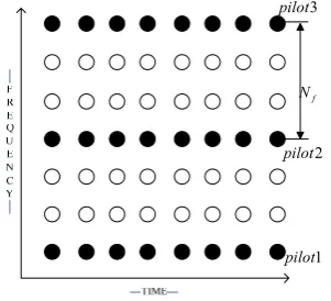
f N 1 pilot 2 pilot 3 pilot
Figure 5. Structure of comb type pilot and block type pilot.
A. LOWPM system for Channel Estimation based on Pilot Sequence and the Structure of Comb-type Pilot
The pilot allocation for channel estimation can improve transmission performance of LOWPM system significantly. The block diagram of LOWPM system for channel estimation based on pilot is given in Fig. 4, in which the constructure of pilot allocation is shown as figure 5.
The structure of comb type pilot is shown in Fig. 5, the black parts are pilot symbols, which are inserted periodically in the frequency axis and frequency interval is Nf . Because all time points have pilot information at
one frequency point of the time-frequency plane, so such pilot structure can overcome time selective fading, suitable for fast fading wireless channel. But because pilot signal is periodic on the frequency axis, so such structure of pilot is more sensitive to frequency selectivity of channel.
In Fig. 4, the received signal is represented as Yn m, =Hn m, Xn m, +wn m, , m=0,1, ,⋅⋅⋅M
where Yn m, represents the received signal in complex
baseband, Xn m, denotes the transmitted signal, Hn m, and
, n m
w are the channel frequency response (CFR) and the
additive Gaussian noise respectively. Here, M is the total number of sub carriers, m is the index of subcarrier
within an LOWPM symbol and n is the index of
LOWPM symbols.
B. Criterion of Channel Estimation
Channel estimation with the aid of pilot in LOWPM systems is performed by estimating the CFR at the pilot locations. This is obtained by comparing the received pilots with the transmitted pilots which are known to the receiver. The received data at the pilot positions is simplified as
Y=PH+w (9) where Pis pilot data, His the channel response at the
pilot position, w is the noise superimposed on pilot
positions.
Least square criterion is to make the difference between observed and estimated results arriving the minimum, so channel response is
( )
1 1
H H
LS
H P P P Y P Y
w H P ∧ − − = =
= + (10)
A data frame is needed to be inserted several pilot sequence, so channel responses of the pilot positions in a data frame can be expressed as
1, , 2, , 3, , , ,
LS LS LS LS K LS
H∧ =⎣⎢⎡H∧ H∧ H∧ ⋅⋅⋅H∧ ⎤⎥⎦ , where K is the
number of inserted pilots in a data frame. LS channel estimation criterion is simple and easy to implement, but when noise is larger, the estimation accuracy is greatly reduced.
Minimum mean square error (MMSE) channel estimation criterion is using the correlation of received signals to suppress noise. When LS estimation contains large noise, MMSE can further smooth with it by using linear estimator. Supposing Wis linear weighted matrix,
then
(
)
(
)
, , 1 1 2 ,p p p p , 1,2,
p MMSE p LS
H
p LS
H H H H n p p
H W H
R R δ X X H p K
∧ ∧
− ∧ −
=
= + = ⋅⋅⋅ (11)
In order to reduce the computational complexity,
(
)
1, ,
p p p p H n m n m
E X⎡⎢ X −⎤⎥
⎣ ⎦is expected to replace
(
)
1
, ,
p p p p
H
n m n m
X X − ,
which is using the average power of data for all sub channel as substitute for instantaneous power of each data. In case source information is equal probability, there is
(
)
1 2, , 1/
p p p p H
n m n m k
E X⎡⎢ X −⎤⎥=E⎡⎣ x ⎤⎦I
⎣ ⎦
where I is unit matrix, in case of equal probability,
average signal-to-noise ratio is
2 2 k E x SNR σ ⎡ ⎤ ⎣ ⎦
= , Eq. 11
can be simplified as[14]:
1
, p p p p ,
p LMMSE H H H H p LS
H R R I H
SNR β −
∧ ⎛ ⎞ ∧
= ⎜ + ⎟
-4 -3 -2 -1 0 1 2 3 4 -0.2 0 0.2 0.4 0.6 0.8 1 1.2 a=-1 a=0 a=1 a=2
Figure 6. Interpolation kernel functions for differentα.
where 2 2
1/
k k
E x E x
β= ⎡⎣ ⎤ ⎡⎦ ⎣ ⎤⎦ , which is a constant determined by the modulation mode, if 16QAM modulation, β=17 /9 ; if 4QAM mapping, β =1 .
,
p p H H m n
R =⎡ ⎤⎣ ⎦r , which is determined by the power and delay of multipath channel.
1 2
(
)
, 0
2 exp
L
m n l l
l
r j m n
N π σ τ − = ⎛ ⎞
=
∑
⎜⎝− − ⎟⎠ (13)Supposing the delay of multipath channel is uniformly distributed, and the power of each path has a negative exponential distribution, namely Ceτ τ/rms
τ
θ = − , thus Eq. 13
can be replaced as[15]
(
)
max , max 2 11 exp ( 1 2 1 exp
c rms
m n
rms
rms rms c
j m n
N r
j m n
N π τ τ τ π τ τ τ ⎡ ⎛ ⎞ ⎤ − ⎢− ⎜ − ⎟+ ⎥ ⎢ ⎝ ⎠ ⎥ ⎣ ⎦ = ⎛ ⎞ ⎛ ⎞ ⎡ ⎤ − − + − ⎜ ⎜ ⎟ ⎢⎟ ⎥ ⎜ ⎝ ⎠ ⎣⎟ ⎦ ⎝ ⎠ (14)
Eq. 14 shows it is only needed to estimate the maximum delay spread τmax and RMS delay spread τrms,
p p
H H
R can be calculated approximately. Above-mentioned
is the channel responses of linear minimum mean square error estimation algorithm.
C. Cubic Convolution Interpolation Algorithm
The channel responses at the pilot positions can be derived from Eq. 12, which is
1, , 2, , , ,
LMMSE LMMSE LMMSE K LMMSE
H∧ =⎡⎢H∧ H∧ ⋅⋅⋅H∧ ⎤⎥
⎣ ⎦
In order to obtain the channel responses of non-pilot positions, frequency domain interpolation is used to calculate the responses of data positions through known channel responses.
The interpolation kernel of cubic convolution function is comprised of cubic subsection function which is defined at (-2,-1), (-1,0), (0,1),(1,2) interval. Cubic convolution interpolation kernel functions of single variable is
3 2
3 2
( 2) ( 3) 1, 0 1 ( ) 5 8 4 , 1 2
0, 2
x x x
g x a x x x x
x
α α
α α α
⎧ + − + + < <
⎪⎪
=⎨ − + − < <
⎪
> ⎪⎩
(15)
where α is bound variable, the interpolation functions corresponding to different value of α are shown in Fig. 6. The cubic convolution interpolation algorithm is applied to LOWPM system, firstly it is needed to determine the value of α. In this paper α is determined by the transmitted pilot information, which is related with the channel environment. Putting α into Eq. 15 to get the interpolation function f x( )=g x( ) |α, which is applied to the interpolation formula, so the channel response function at the non-pilot positions is
(
)
3
n 0
( ) 1
( 1) ( ) 2
( 1) ( 2) ( 1 ( 1) p p p p p p p p p p p p p p p N
H k H m i
N
N i i
f H m f H m
N N
N i N i
f H m f H m
N N
n N i
f H m n
N ∧ ∧ ∧ ∧ ∧ ∧ ∧ = ⎛ ⎞ = ⎜⎜ − + ⎟⎟ ⎝ ⎠ ⎛ + ⎞ ⎛ ⎞ = ⎜⎜− ⎟⎟ − + −⎜⎜ ⎟⎟ ⎝ ⎠ ⎝ ⎠ ⎛ − ⎞ ⎛ − ⎞ + ⎜⎜ ⎟⎟ + + ⎜⎜ ⎟⎟ + ⎝ ⎠ ⎝ ⎠ ⎛ − − ⎞ = ⎜⎜ ⎟⎟ + − ⎝ ⎠
∑
) (16)where 1≤ ≤m K , 1
p
N i
N ≤ < ,
p
N
N is the interval between adjacent pilot.
The form of above expression is similar to the convolution between f t
( )
and the channel impulseresponse at pilot position, so we call this kind of interpolation method as cubic convolution interpolation.
The implementation steps of LMMSE channel estimation based on cubic convolution interpolation is as follow.
Step 1: Calculating channel responses at pilot positions using Eq. 12, which is
1, , 2, ,..., ,
LMMSE LMMSE LMMSE K LMMSE
H∧ =⎡⎢H∧ H∧ H∧ ⎤⎥
⎣ ⎦.
Step 2: Calculating the channel responses at non-pilot positions Using the results of step 1, the computing formula shown as Eq. 16.
In order to compare the BER performance of LOWPM system using different interpolation method, the formulas of other interpolation are given as follow:
1. Linear interpolation algorithm:
( )
(
)
( )
(
)
( )
1 1 / pp p p
p
N
H k H m i
N i
H m H m H m
N N ∧ ∧ ∧ ∧ ∧ ⎛ ⎞ = ⎜⎜ − + ⎟⎟ ⎝ ⎠ ⎡ ⎤ = + ⎢ + − ⎥ ⎣ ⎦
where 1≤ ≤m K, 1
p
N i
N ≤ < .
-20 -15 -10 -5 0 5 10 15 20 10-5
10-4 10-3 10-2 10-1 100
SNR/dB
BE
R
Gauss channel
Rayleigh channel without Dopple frequency shift multipath Rayleigh channel whit Dopple frequency shift 132Hz
Figure 7. Comparison of BER for LOWPM system under different channel taking no channel estimation (using QAM4 mapping).
-20 -15 -10 -5 0 5 10 15 20
10-4 10-3 10-2 10-1 100
SNR/dB
BER
Gauss channel
Rayleigh channel without Doppler frequency shift multipath Rayleigh channel with Doppler frequency shift 132Hz
Figure 8. Comparison of BER for LOWPM system under different channel taking no channel estimation (using QAM16 mapping).
( )
(
)
(
)
( )
(
)
1 0 1
1
1 1 1 , 1
p
p p p
p
N
H k H m i
N
C H m C H m C H m
N
m K i
N
∧ ∧
∧ ∧ ∧
−
⎛ ⎞
= ⎜⎜ − + ⎟⎟
⎝ ⎠
= − + + +
≤ ≤ ≤ <
Where 1 ( 1)
2
a a
C− = − , C0= − −(a 1)(a+1) , 1 ( 1) 2
a a
C = + ,
i a
N = .
IV.SIMULATIONS AND ANALYSIS
In order to prove the effectiveness and feasibility of the proposed algorithm, simulations for the BER performance of LOWPM system under various channel conditions using LMMSE channel estimation algorithm based on cubic convolution interpolation are performed. Simulation parameters are shown in Table 1.
A. Simulations of LOWPM System under Different Channel Condition when No Channel Estimation
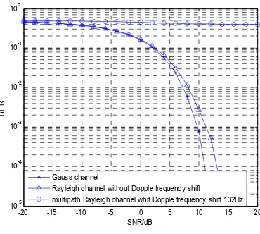
Taking no channel estimation technique, simulating the BER performance of LOWPM system under different channel which are Gaussian channel, Rayleigh channel without Doppler frequency shift and multipath Rayleigh channel with Doppler frequency shift of 132Hz, the results are shown in Fig. 7 and Fig. 8.
Fig. 7 shows, the BER performance of LOWPM system which takes QAM4 mapping in multipath Rayleigh fading channel is good and is slightly worse only than that in Gauss white noise channel, which shows the ability to anti-multipath fading of LOWPM system. But when there is Doppler frequency shift existing in multipath Rayleigh fading channel, the performance of system deteriorates and bit error rate has been in a high state. In mobile communication, the mobile station are mostly in the moving state so that Doppler frequency shift is inevitable. Therefore, the
channel estimation technique is a key measure for improving the performance of system.
Fig. 8 is BER performance of LOWPM system which takes QAM16 mapping. Fig. 7 and Fig. 8 indicate, along with the increasing of modulation order, system performance under various channel conditions are declining and the ability to anti multipath interference is also on the decline.
B. Simulations for Cubic Convolution Interpolation based LMMSE Channel Estimation Algorithm
In order to determine the cubic convolution interpolation function, the relation between αand SNR is shown in Fig. 9. With the increasing of SNR, the BER performance of system is improved, the lowest level of each curve is almost at α =0. So in next simulation, α is set to 0.
TABLE I. SIMULATION PARAMETERS
Parameter value
Modulation wavelet db2
System Bandwidth 1MHz
Number of sub channel 8
Each path's delay time of multipath
Rayleigh fading channels [0,0.2e-6,0.4e-6,2e-6,4e-6]
Power of each channel(dB) [0, -3.77, -7.55, -30, -70 ]
Center frequency of modulation
signal 2GHz
-20 -15 -10 -5 0 5 10 15 20 10-3
10-2 10-1 100
SNR/dB
BER
linear interpolation two order interpolation cubic convulution interpolation
Figure 11. Comparison of BER for different interpolation algorithm (using QAM16 mapping).
-2 -1 0 1 2 3 4
10-2
10-1 100
α
BER
comparison of BER for different α
SNR=10dB SNR=15dB SNR=20dB
Figure 9. Comparison of BER for differentα.
-20 -15 -10 -5 0 5 10 15 20
10-5 10-4 10-3 10-2 10-1 100
SNR/dB
BER
comparison of different interpolation
no channel estimation two order interpolation based LS cubic convolution interpolation based LS two order interpolation based LMMSE cubic convolution interpolation based LMMSE
Figure 10. Comparison of BER for different interpolation algorithm (QAM4 mapping mode).
When there is Doppler frequency shift existing in communication system, the channel estimation technique can greatly enhance the performance of system. As shown in Fig. 10, LS channel estimation algorithm makes the BER performance of LOPWM system close to Fig.7 where no Doppler frequency shift exists. The BER performance of LMMSE algorithm in Rayleigh channel with Doppler frequency shift is almost the same as that in Gauss channel. In QAM4 mapping mode, LMMSE estimation criterion performs slightly better than LS criterion, there is 2dB gain when BER is 10-3. The cubic convolution interpolation based LMMSE channel estimation algorithm is better than other channel estimation methods. Compared with two-order interpolation based LMMSE algorithm, the proposed algorithm has 1.2dB gain when BER is 10-3.
From Fig. 11, it is known that when SNR is -20~5dB, the performance of the three kinds of interpolation algorithm are almost equal. When SNR is 5~20dB, the BER performance of system using cubic convolution
interpolation algorithm is better than other interpolation algorithms. And with the increasing of SNR, the proposed algorithm to system performance improves dramatically.
V. CONCLUSIONS
The property of self orthogonal for integer translation of wavelets and the mutual orthogonality of wavelets in different subspace can overcome ISI and ICI so that gaining a lot of focus. Lifting scheme based wavelet transform can be calculated in situ, its computational efficiency is two times as that of Mallat algorithm. Therefore, the study of LOWPM system has practical significance. Aiming at the problem that the performance of system deteriorates when there is Doppler frequency shift existing in multipath Rayleigh fading channel, cubic convolution interpolation based LMMSE channel estimation algorithm is put forward in this paper. Simulation results show that this algorithm can effectively improving the performance of LOWPM system, for further study of LOWPM and the application of this technology in the future mobile communication to lay certain foundation.
REFERENCES
[1] S.B.Weinstein and P.M.Ebert, “Data Transmission by Frequency Division Multiplexing Using the Discrete Fourier Transform,” IEEE Transactions on Communications, vol. 5, pp. 628-634, 1971.
[2] Yujie Zhang, Huiming Peng, Hongwei Li, “Wavelet Packet Transform-Based Algorithm for Mixing Matrix Estimation,” Journal of Computers, vol.7, no.11, 2012. [3] Nawaz, T. and Baig, S., “Wavelet OFDM - A solution for
reliable communication in a frequency selective Rayleigh fading channel,”International Bhurban Conference on Applied Sciences and Technology, Islamabad, Pakistan, 2012, pp. 413-417.
on wavelet packet,” International Forum on Strategic Technology, Harbin, China, 2011, pp. 902-906.
[5] M. Oltean and A. Isar, “On the time-frequency localization of the wavelet signals, with application to orthogonal modulations,” International Symposium on Signals,Iasi, Romania, 1998, pp. 173-177.
[6] W. Sweldens, “The lifting scheme: A construction of second generation wavelets,” SIAM J. Math. Anal., vol. 2, pp. 511- 546, 1998.
[7] I. Daubechies and W. Sweldens, “Factoring wavelet transforms into lifting steps,” J. Fourier Anal. Appl., vol. 3, pp. 245-267, 1998.
[8] Mahesh Kumar Gupta, Sarika Shrivastava, A.S.Raghuvanshi et al., “Channel estimation for wavelet based OFDM system,” International Conference on Devices and Communication, Bali Island, Indonesia, 2011, pp. 1-4.
[9] Canute Vaz and David G. Daut, “Effect of Wavelet Choice in Fast-Fading Channel Estimation Using Wavelet Transform-Based Deconvolution,” International Symposium on Communication and Information Technologies, Hangzhou, China, 2011, pp. 93-96.
[10]Bor-Sen Chen, Chang-Yi Yang, Wei-Ji Liao, “Robust Fast Time-Varying Multipath Fading Channel Estimation and Equalization for MIMO-OFDM Systems via a Fuzzy Method,” IEEE Transactions on vehicular technology, vol. 61, pp. 1599-1609, 2012.
[11]Po-Lin Chiu, Lin-Zheng Huang, Li-Wei Chai and Yuan-Hao Huang, “Interpolation-Based QR Decomposition and
Channel Estimation Processor for MIMO-OFDM System,”IEEE Transactions on Circuit and Systems, vol. 5, pp. 1129-1140, 2011.
[12]Hamid Reza Tanhaei and Seyed Ali Ghorashi, “A Novel Channel Estimation Technique for OFDM Systems with
Robustness against Timing Offset,” IEEE Transactions on Consumer Electronics, vol. 2, pp. 348-356, 2011.
[13]Yunlv Hong, Di He, “An Improved Doppler Frequency Offset Estimation Algorithm of OFDM System under High-speed Movement Environment,” Journal of Computers, vol.8, no.12, 2013.
[14]A.Bajpai, M.K.Lakshmanan and H.Nikookar, “Channel Equalization in Wavelet Packet Modulation by Minimization of Peak Distortion,”IEEE International Symposium on Personal Indoor and Mobile Radio Communications, Delft, Nethelands, pp. 152-156, 2011. [15]3GPP TR25.814, V7.1.0. Phyisical Layer Aspects for
Evolved Universal Terrestrial Radio Access (UTRA) (Release 7), 2006-09.
GeweiTan was born in Guiyang, China,