Comparison of Sheet Metal Forming Simulation
and Try-Out Tools in Design of Tooling
Nikhil Balkhande Dr. Sachin A. Mastud
PG Student M.Tech Professor & Head of Department Department of Production Engineering Department of Production Engineering
V.J.T.I, Matuga V.J.T.I, Matuga
Abstract
Sheet metal forming simulation softwares are used to predict formability of various industrial components. Traditionally trials are taken on try-out tools to test the tool designing before hard tools are manufactured. Sheet metal forming simulation can test increased number of tool design than that of try-out tools also we can use them at early stage of design phase. Sheet metal forming simulation is having high level of accuracy in the result to replace the trial phase to great extent. In this paper comparison in results of sheet metal forming simulation and try-out tools during designing of tooling is done. ANSYS simulation software is used to test the design of tooling.
Keywords: Sheet Metal Forming Simulation, Formability, Try-Out Tools, ANSYS
________________________________________________________________________________________________________
I.
INTRODUCTION
Sheet metal forming is may referred as stamping process in this operation the blank is stretched between the die and punch. In sheet metal forming deformation is limited because of various defects like wrinkling, spring back and tearing which makes difficult to meet the quality requirement. Design of die and punch are tested by building try-out tools to check ability of certain tool design to produce required quality. Try-out tools are made of much cheaper material like kriksite to reduce the production cost but still it is very time consuming and costly method. Today more efficient method is available- sheet metal forming simulation. Sheet metal forming simulation software evaluates performance of die and punch and forming process. FEM is most common method of sheet metal forming operation to determine whether purposed design will produce part free of defects such as wrinkling and fracture. Due to use of this technique time is reduced to a factor of 15 and cost to a factor of 10. Today the accuracy of sheet metal forming simulation is high enough to replace the use of try out tools.
II.
METHOD
The aim of this study is to analyse the advantages of sheet metal forming simulation over the try-out in design of forming tool. In this study ANSYS simulation software is used. The die punch assembly simulation is done in ANSYS. The results of simulation are compared with the try out tools results. The method used in this study is Production Reliability Matrix (Rundqvist and Stahl, 2001). In production reliability matrix different parameters effect is categorised in different factor group. Effect of each parameter is then assessed on the scale of 1-4. Based on the result of matrix the parameter which are having considerable effect on forming process are separated and the priority list is for eliminating effect of these parameter are made.
III.
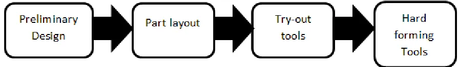
PROCESS OF DESIGNING FORMING TOOLSFig.1 shows the process for designing tool traditionally and Fig.2 shows the process for designing tool using sheet metal forming simulation.
Fig. 2: Process of Designing Tool with Sheet Metal Forming Simulation
Traditionally process of designing the tool includes try out phase where extensive trials taken to check whether tool geometry. This very important phase in tool designing phase, where it is checked whether the part will be produced as per required quality. It is very difficult to predict forming process. By using sheet metal forming simulation try-out phase is completely eliminated due to this considerable amount of time and cost is saved.
Finite Element Method: A.
The finite element method is a numerical method, which can solve many problems. The analysis which uses FEM is known as FEA. A FEA program consists of three modules; pre-processor, a solver, and post processor. FEA programs is able to handle large number of nodes and nodal degrees of freedom if powerful hardware tool is provided.
ANSYS Analysis: B.
ANSYS analysis has following three basic steps:
Model Building: 1)
It is the most time consuming process in the analysis. User gives name to the part and analysis title which has to perform. B y using pre-processor material properties, model geometry. Constants are defined
Loading Conditions: 2)
The aim of ANSYS analysis is to study how a structure behave to certain loading condition. Therefore it is necessary to give proper loading condition. In ANSYS loads can be applied through different ways. In ANSYS loads means boundary conditions and externally and internally applied forces.
Review The Results (Post Processing): 3)
In ANSYS postprocessor gives solution to particular loading conditions. In Post processing results of the analysis are reviewed. It is most important step in analysis.
Use of Try-Out Tools: C.
IV.
RESULTS
Results of Sheet Metal Forming Simulation: A.
Sheet metal forming result can predict following defects:- 1) Thickness distribution
2) Risk of fracture 3) Wrinkles 4) Surface defects 5) Spring-back 6) Material behaviour
7) Forces (Punch, blank holder)
Fig. 3: Simulation Results Showing Various Defects in Forming
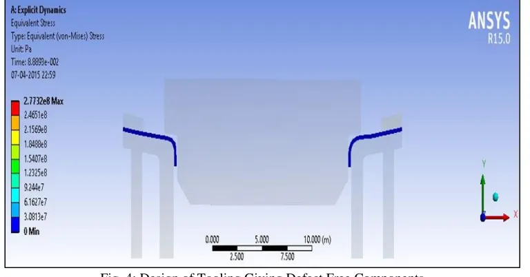
In figure 3 die-punch assembly of industrial component is taken for testing its design. As we can see various defects like wrinkling, galling is observed in figure. This shows that it is necessary to change design of tooling to get defect free component. So the design of die punch is modified and its result is shown in Figure 4.
Fig. 4: Design of Tooling Giving Defect Free Components
Try-Out Tools Results: B.
Fig. 5: Prototype Showing Defect From Primary Design of Tooling
From figure 5 the primary design of the tooling is showing wrinkling defect as it is shown by the simulation software therefore there is need for changing the design of the tooling.
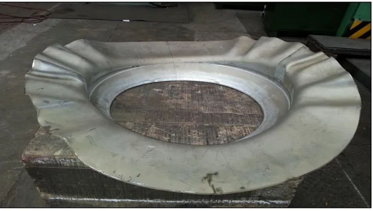
The design of the tooling is done such that the defect free product will be produced. Figure 6 shows the prototype which is obtained from modified tooling geometry which is having required geometry and it is defect free.
Fig. 6: Prototype Showing Defect Free Component from Modified Design of Tooling
Production Reliability Matrix: C.
In Production Reliability Matrix comparison between various parameters which can be predicted and verified in sheet forming simulation and try-out tools is made.
Table - 1 Production Reliability Matrix
Parameters Simulation results Try-out tools
Thickness distribution 3 3
Risk of fracture 3 3
Wrinkles 3 3
Surface defects 2 3
Spring-back 3 3
Galling 3 3
Forces(Punch) 3 3
Forces(Punch holder) 3 3
In table 1 following scale is used:-
4 – The results show perfect prediction of production process 3- The results show direct prediction of production process 2- The results show indirect prediction of production process 1- The result cannot predict production process at all.
V.
CONCLUSIONS
1) Analysis of table 1 shows various advantage of sheet metal forming simulation over try-out tools. Biggest advantage of simulation software is that we can test different design of parts, tools and processes. Whereas try-out tools are limited and expensive means we can produce only minimum number of the try-out tools which limits possibility of testing. 2) The use of sheet metal forming simulation gives significant reduction of time and cost compared to use of try-out tools.
From Table 1 for various parameters the simulation corresponds well with actual production process. Sheet metal forming simulation is superior to try-out tools in regards predicting and verifying forming process.
ACKNOWLEDGEMENT
I would like to acknowledge with much appreciation the crucial role of Mr. Amol Raut, Manager of Larsen & Turbo, Powai, and PC-2 for their valuable comments, sharing time and knowledge on the research carried out during this project.
REFERENCES
[1] ASM Handbook Volume 14-B Metal working: Sheet Forming, Prepared under the direction of the ASM International Handbook Committee, S.L. Semiatin , Volume Editor
[2] M. Kadkhodayan, F. Moayyedian “Analytical elastic–plastic study on flange wrinkling in deep drawing process” Department of Mechanical Engineering, Ferdowsi University of Mashhad, Mashhad, P.O. Box 91775-1111, Iran
[3] Jawad Ahmed , Jadoon and Irfan A. Manarvi “Wrinkling in Aluminium Sheet under Bi-Axial Loading using Finite Element Analysis” Department of Mechanical Engineering, HITEC University Taxila, Pakistan. International journal of Multidisciplinary sciences and engineering.
[4] R. Raman Goud, K.Eswar Prasad, Swades Kumar Singh “Formability limit diagrams of extra-deep-drawing steel at elevated temperatures” Dept. Of Mechanical Engineering, GRIET, Hyderabad. 3rd International conference on Materials Processing and characterisation.
[5] Xi Wang, Jian Cao “Wrinkling Limit in Tube Bending” Department of Mechanical Engineering, North western University, Evanston, IL 60208
[6] Fuh-Kuo Chen, Shen-Fu Ko “Deformation analysis of spring back in L-bending of sheet metal” Department of Mechanical Engineering, National Taiwan University, Taipei, Taiwan R.O.C.
[7] Gawade Sharad, V. M. Nandedkar “Spring-back in Sheet Metal Bending-A Review” S.G.G.S. Institute of Engineering and Technology, Nanded-India. [8] Nitin Kotkundea, Aditya D. Deolea, Amit Kumar Gupta “Prediction of Forming Limit Diagram for Ti-6Al-4V Alloy Using Artificial Neural Network”
Department of Mechanical Engineering, BITS-Pilani, Hyderabad Campus, Hyderabad. 3rd International conference on Materials Processing and characterisation.