Comparative Studies in Analysis and Design of
RCC Structures with and without Infill Wall
under Seismic Effect
Bhnaupratap R Mehadia Dr. U. P. Waghe
PG Student Principal & Professor
Department of Civil Engineering Department of Civil Engineering
Yeshwantrao Chavan College of Engineering, Nagpur Yeshwantrao Chavan College of Engineering, Nagpur
Abstract
Reinforced concrete frames with masonry infill walls are a common practice in countries like India, where the region is prone to seismic activity. Generally the masonry infill walls are treated as non-structural element in structural analysis and only the contribution of its mass is considered and it’s structural properties like strength and stiffness is generally not considered. The structures in high seismic areas are greatly vulnerable to severe damages. Apart from the gravity load structure has to withstand to lateral load which may develop high stresses. Now day’s reinforced concrete frames are most common in building construction practice around the globe. The vertical gap in reinforced concrete frames i.e. created by the columns and beams are generally filled in by brick or masonry and it is referred as brick infill wall or panels. When the construction of frame is done, these walls are built of brunt clay bricks in cement mortar. These walls are typically of 200 to 115 mm thick. Due to functional requirements the openings is provided in the frames for windows and doors etc.
Keywords: RCC Structure, masonary infill, RCC frame, diagonal strut, dynamic analysis, displacement
________________________________________________________________________________________________________
I. INTRODUCTION
Earthquake is responsible for ground motion in random fashion, both horizontally and vertically, in all directions radiating from the epicenter. Consequently, structures founded in ground vibrate, inducing inertial forces on them. The structures in high seismic areas are greatly vulnerable to severe damages. Apart from the gravity load structure has to withstand to lateral load which may develop high stresses. The major reason behind the use of infill in building is the ease with which it can be constructed that is it generally requires the locally available material. Again it has the good sound proofing and heat insulating properties those results in the greater comfort for the inhabitants of the buildings.
To understand the effect of infill masonry on the lateral strength and stiffness of structures various experiments have been conducted since early 50’s. Actually the lateral load carrying mechanism is modified from the primary frame action to primary truss action by the effect of infill, which causes the increase in axial force and decrease in bending moment and shear force of the frame members. There is generally increase in damping of structures due to the generation of cracks with growing lateral drift. The infill walls may adversely affect the structure during the seismic excitation if it is not placed properly. The non-appearance of infill wall in a certain storey may lead to the soft storey effect which is one of the major ill effects of the infill walls.
Objective of This Paper:
1) To analyze the effect of infill wall on displacement of reinforced concrete frame under seismic loads. 2) To study the seismic behaviour of reinforced concrete frame with and without in filled wall.
II. WORK CARRIED OUT
A G+12 floors reinforced concrete building analysis is carried out using STAAD Pro V8i software. The lateral loads to be applied on the buildings are based on the Indian Standard. Building is analysed according to IS 456-2008 and earthquake loading is applied as per the recommendation of IS 1893-2002. Different configurations of frames with and without infill wall are taken and analyzed. The study is performed for seismic zone II,III,IV,V as per IS 1893-2002.
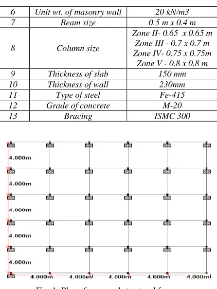
Table – 1
Details of model data of the building
Sr No. Description Parameter
1 Depth of foundation 2.0 m
2 No. of stories G + 12
3 Type of building use Residential
4 Floor to Floor height 3.0m
6 Unit wt. of masonry wall 20 kN/m3
7 Beam size 0.5 m x 0.4 m
8 Column size
Zone II- 0.65 x 0.65 m Zone III - 0.7 x 0.7 m Zone IV- 0.75 x 0.75m
Zone V - 0.8 x 0.8 m
9 Thickness of slab 150 mm
10 Thickness of wall 230mm
11 Type of steel Fe-415
12 Grade of concrete M-20
13 Bracing ISMC 300
Fig. 1: Plan of proposed structural frame
Modelling:
Building frame with the following geometrical types are considered for analysis in 4 different seismic zones (Zone II, Zone III, Zone IV and Zone V) for seismic and gravity loading in each configurations of frames.
III. RESULT
Maximum Lateral Displacements:
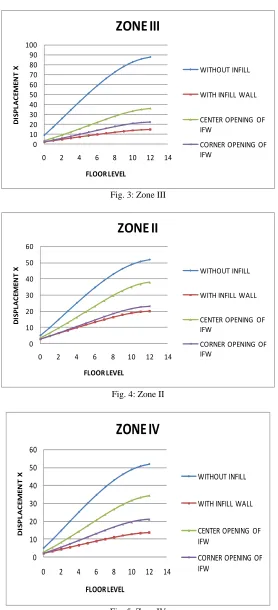
The lateral displacements of structure for the cases of dead and live load for seismic analysis in all the three directions are presented in Table 2&3. The results are compared with that of buildings with and without infill wall. It is observed that the maximum lateral displacements are reduced due to the presence of infill wall. It is observed that the lateral displacements are reduced to the largest extent for infill wall systems as compare to that of without infill wall for all seismic zones.
Table – 2
Maximum Lateral Displacement in mm. in X direction Displacements in (mm) of Structure
Fig. 3: Zone III
Fig. 4: Zone II
Fig. 5: Zone IV 0 10 20 30 40 50 60 70 80 90 100
0 2 4 6 8 10 12 14
D IS P LA C E M E N T X FLOOR LEVEL
ZONE III
WITHOUT INFILLWITH INFILL WALL
CENTER OPENING OF IFW
CORNER OPENING OF IFW 0 10 20 30 40 50 60
0 2 4 6 8 10 12 14
D IS P LA C EM EN T X FLOOR LEVEL
ZONE II
WITHOUT INFILLWITH INFILL WALL
CENTER OPENING OF IFW
CORNER OPENING OF IFW 0 10 20 30 40 50 60
0 2 4 6 8 10 12 14
D IS P L A C E M E N T X FLOOR LEVEL
ZONE IV
WITHOUT INFILLWITH INFILL WALL
CENTER OPENING OF IFW
Fig. 6: Zone V
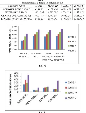
Maximum Forces and Bending Moments in Columns:
The maximum axial force and bending moments in columns of the building frame without infill wall, for dead and live load analysis and for seismic analysis is presented in Table 4 to Table 5. The results are compared with that of building frames with various openings of infill wall. The results in all the three directions are obtained. So in overall it may say that axial forces are reduced when we provide different openings to infill wall system as they might be distributed in between members. Further, while infill wall decreases the bending moments in column.
Table – 4
Maximum axial forces in column in Kn
Structure Types ZONE-II ZONE-III ZONE-IV ZONE-V WITHOUT INFILL WALL 4261.909 4272.436 4481.454 4637.587 WITH INFILL WALL 4514.97 4585.994 4704.529 4852.152 CENTRE OPENING INFILL 4474.89 4584.244 4699.757 4821.525 CORNER OPENING INFILL 4484.427 4596.263 4713.333 4884.879
Fig. 7: 0 20 40 60 80 100 120 140 160 180 200
0 2 4 6 8 10 12 14
D IS P L A C E M E N T X FLOOR LEVEL
ZONE V
WITHOUT INFILLWITH INFILL WALL
CENTER OPENING OF IFW
Table – 5
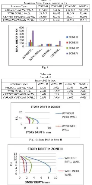
Maximum Shear force in column in Kn
Structure Types ZONE-II ZONE-III ZONE-IV ZONE-V WITHOUT INFILL WALL 131.887 210.34 138.323 508.009 WITH INFILL WALL 28.743 30.662 31.048 73.464 CENTRE OPENING INFILL 85.303 85.704 86.019 86.301 CORNER OPENING INFILL 50.951 51.262 51.555 182.13
Fig. 9:
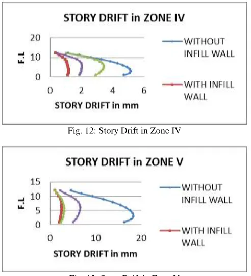
Table – 6 Story drift Storey drift in (mm)
Structure Types ZONE-II ZONE-III ZONE-IV ZONE-V
WITHOUT INFILL WALL 5.426 8.623 5.165 18.268
WITH INFILL WALL 1.784 1.279 1.201 2.644
CENTRE OPENING INFILL 3.441 3.29 3.179 3.092
CORNER OPENING INFILL 2.051 1.966 1.902 6.628
Fig. 10: Story Drift in Zone II
Fig. 12: Story Drift in Zone IV
Fig. 13: Story Drift in Zone V
IV. OBSERVATIONS & CONCLUSIONS
- It is observed that the maximum lateral displacements are reduced due to the presence of infill wall. - It has been concluded that the displacement of the structure decreases as infill wall is used in system.
- The presence of infill wall can affect the seismic behaviour of frame structure to large extent, and the infill wall increases the strength and stiffness of the structure.
- The Axial force goes on decreasing as infill wall with different openings like corner and centre are provided. - Infill wall decreases the bending moment in the column.
- The seismic analysis of RC frames should be done by considering the infill walls in the analysis. For modelling the infill wall the equivalent diagonal strut method can be effectively used.
REFERENCES
[1] Bertero, V, & Brokken, S. (1983). Infills in seismic resistant building of Structural Engineering,109(6), 1337 1361.
[2] Korkmaz, K. A., Demir, F., & Sivri, M. (2007). Earthquake assessment of R/C structures with masonry infill walls.International journal of science & technology,2(2), 155-164.
[3] Hashemi, S. A. (2007). Seismic evaluation of reinforced concrete buildings including effects of masonry infill walls. University of California, Berkeley. [4] Crisafulli, F. J, Carr, A. J, & Park, R. (2000). Analytical modeling of infilled frame structures-a general review.Bulletin-New Zealand Society for
Earthquake Engineering,33(1), 30-47.
[5] Canbay, E, Ersoy, U, & Ozcebe, G. (2003). Contribution of reinforced concrete infills to seismic behavior of structural systems. ACI Structural Journal,100(5).
[6] Sattar, S., & Liel, A. B. (2010, July). Seismic performance of reinforced concrete frame structures with and without masonry infill walls. In9th US National and 10th Canadian conference on earthquake engineering, Toronto, Canada.
[7] Hossein, M., & Kabeyasawa, T. (2004). Effect of infill masonry walls on the seismic response of reinforced concrete buildings subjected to the 2003 Bam earthquake strong motion: a case study of Bam telephone center.
[8] Das, D, & Murty, C. V. R. (2004). Brick Masonry infills in seismic design of RC framed buildings: Part 1-Cost implications.IndianConcrete Journal,78(7), 39-44.
[9] Chiou, Y. J, Tzeng, J. C, & Liou, Y. W. (1999). Experimental and analytical study of masonry infilled frames.Journal of Structural Engineering,125(10), 1109-1117.
[10] Dawe, J. L, & Seah, C. K. (1989). Behavior of masonry infilled steel frames. Canadian Journal of Civil Engineering,16(6), 865-876.