Study on Approach of Determining Size of
µC/OS-II Task Stack
Guangjian Zhang
School of Computer Science and Engineering, Chongqing University of Technology, Chongqing, China Email: [email protected]
Zheng Liu
School of Computer Science and Engineering, Chongqing University of Technology, Chongqing, China Email: [email protected]
Abstract—When µC/OS-II is taken as the operating system
of an embedded system, the stack size of every task is needed to be assigned, but it is difficult to determine the stack size of µC/OS-II task with existing methods. In this paper, an approach of determining stack size of µC/OS-II task was presented. In order to clarify the memory space size which is needed by single element in a µC/OS-II task stack, the contents of µC/OS-II task stack were analyzed. Secondly, some tree structures were defined, which can describe the extreme usage of task stack. Lastly, two formulas used to determine size of task stack were presented. As long as the source codes of µC/OS-II operating system and its task are obtained, the stack size of the task can be computed accurately with the approach presented by this paper. The result acquired with the approach is the maximum size of task stack, it can meet the needs of µC/OS-II task for stack space at any cases.
Index Terms—µC/OS-II; task stack; size; Function tree;
Interrupt tree; Extreme tree
I. INTRODUCTION
In embedded system domain, as a result of opening source code as well as nearly free characteristic, the embedded operating system µC/OS has caused intense reaction. No matter beginners or experienced engineers, they can develop and debug a µC/OS-based embedded system conveniently with the opening source code of
µC/OS. Any schools can acquire µC/OS operating system source code freely, so many schools take it as an example of embedded operating system, this makes many students be familiar to µC/OS operating system. In recent ten years, hundreds of thousands of students are trained to develop µC/OS-based embedded systems. In commercial project, project exploiter only needs to pay few copyright fee to apply µC/OS operating system. Since published,
µC/OS operating system has been applied to industrial control, transportation, communication and energy project. µC/OS-II is the improvement of µC/OS operating
system. Nowadays, µC/OS-II usually is applied to
µC/OS-based embedded system.
µC/OS-II is multi-tasks operating system and can have 64 tasks. Each µC/OS-II task needs independent stack space. For a task, its stack is important, because the stack is used when the task is created, interrupted and switched to other task. The capacity of µC/OS-II task stack needs to be assigned by application program,
µC/OS-II itself cannot determine it.
It is necessary to determine accurately the capacity of
µC/OS-II task stack. It not only can guarantees reliable operation of application system, but also can avoid to allocate excessive stack space. Nowadays, it is difficult to determine the capacity of µC/OS-II task stack accurately.
Although µC/OS-II operating system provides a function named OSTaskStkChk() to test the capacity of task stack, but this test can not go through the worst stack usage, the result of test may be much smaller than the size required at worst case. So the test is rough, the result of test can not serve as basis of assigning the size of task stack[1].
Many developers of µC/OS-based embedded system presented approaches which solve the problem [2-4]. The common aspect of these approaches is to change µ C/OS-II task stack structure by changing each task having independent stack space to all task using a common stack space. These methods can reduce the demand of RAM space, but cannot calculate the capacity of µC/OS-II task stack accurately. Moreover, the changing of µC/OS-II operating system kernel will bring the risk of instability.
In contrast, this paper proposed one new method which does not modify µC/OS-II operating system kernel. Through the method, the capacity of µC/OS-II task stack can be calculated accurately.
In this paper, Section 2 analyzes the structure of
µC/OS-II task stack, clarifies the contents of µC/OS-II task stack, and divides the capacity of the task stack into three sections. Section 3 defines some data structures, which can show the changes of the contents of µC/OS-II task stack. Section 4 presents an approach through which the capacity of µC/OS-II task stack can be calculated accurately. Section 5 shows an example of applying the approach.
II. CONTENTS OF ΜC/OS-II TASK STACK
Before calculating the capacity of µC/OS-II task stack, The contents of task stack should be clarified. Even if the contents of task stack change with the state of task, data in µC/OS-II task stack are divided into five categories. They are local variables, parameters of functions, returning address of functions, program breakpoints and breakpoint data[5,6].
A µC/OS-II task has five states, they are sleeping state, ready state, running state, waiting state and interrupted state. In specific time, the task is in one of the five states. The contents of task stack change continuously with the task states. When analyzing the contents of task stack, we must consider all cases, they include the nesting of all function called by the task, the nesting of all ISR (i.e. interrupt service routine) and switching between two tasks.
When the task is in sleeping state, it has not been created, so it don’t need stack space.
When a task is in ready state, its stack need to store parameters of the task, local variables of the task, the first address of the task or the breakpoint, the breakpoint data, parameters of all functions called by the task directly or indirectly, local variables of all functions called by the task directly or indirectly and return address of all functions called by the task directly or indirectly. When the task is created justly, it is in a special ready state. At this time, its stack only needs to store the first address of the task, parameters of the task, local variables of the task and initial values of CPU registers. Breakpoint is the address from which the task can continue to run when it is scheduled. Breakpoint is in task code or a function called by the task directly or indirectly and stored into the stack of the task when the task is switched to another task. Breakpoint data are the context which the task used when the task was switched to another task, it is usually the values of CPU registers. When the task is scheduled, it starts to run from the address of the task or the breakpoint which is stored in its stack. A function called by the task directly may call other function, therefore function nest may exits. If functions are nested, the task stack needs to store the parameters, local variables and return address of all functions which are nested. So, the task stack must provide space to save the parameters, the local variables and the return address for multiple functions.
When the task is in running state, its stack needs to store parameters of the task, local variables of the task, parameters of all functions called by the task directly or indirectly, local variables of all functions called by the task directly or indirectly and returning address of all functions called by the task directly or indirectly.
When the task is in waiting state, its stack needs to store parameters of the task, local variables of the task, the breakpoint, the breakpoint data, parameters of all functions called by the task directly or indirectly, local variables of all functions called by the task directly or indirectly and returning address of all functions called by the task directly or indirectly. Breakpoint is either in the task or in a function called by the task directly or indirectly.
When a task is in interrupted state, its stack needs to store parameters of the task, local variables of the task, the breakpoints, the breakpoint data, parameters of all functions called by the task directly or indirectly, local variables of all functions called by the task directly or indirectly, return address of all functions called by the task directly or indirectly, breakpoints of all ISRs, breakpoint data of all ISRs and local variables of all ISRs. In ready or waiting state, the task stack only needs to store one breakpoint, but in interrupted state, a ISR interrupted by other interrupt source whose priority is higher has a breakpoint also. Therefore, there are many breakpoints. Similarly, there are many breakpoint data.
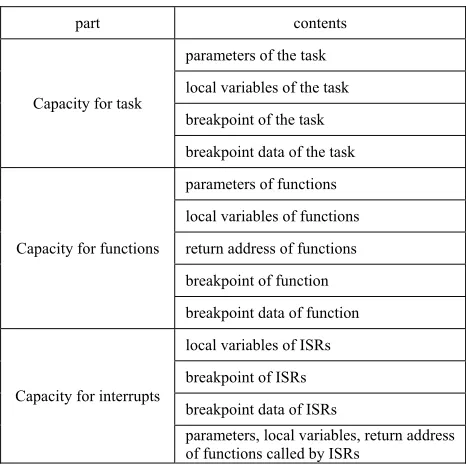
From the analysis above, µC/OS-II task stack uses to store three types of information, they are information related to task code, and information related to all functions, and information related to the ISR. The information related to task code includes the parameters of the task, the local variables of the task, the breakpoint and the breakpoint data of the task. The information related to all functions includes the parameters of functions called by the task directly or indirectly, the local variables of all functions called by the task directly or indirectly, the return address of all functions called by the task directly or indirectly, the breakpoint and breakpoint data of function called by the task directly or indirectly. The information related to ISRs includes the local variables of all ISRs, the breakpoints and the breakpoint data of ISRs which are interrupted by other interrupt source whose priority is higher, the parameters of functions called by ISRs, the local variables of functions called by ISRs, the return address of functions called by ISRs. Therefore, the capacity of µC/OS-II task stack consists of the capacity needed by the task, the capacity needed by all functions, and the capacity needed by ISRs. The three parts are named Capacity for task, Capacity for functions, and Capacity for interrupts. The three parts and their contents are shown by Tab. I.
TABLE I. THREE PARTS OF THE CAPACITY OF TASK STACK
part contents
Capacity for task
parameters of the task
local variables of the task
breakpoint of the task
breakpoint data of the task
Capacity for functions
parameters of functions
local variables of functions
return address of functions
breakpoint of function
breakpoint data of function
Capacity for interrupts
local variables of ISRs
breakpoint of ISRs
breakpoint data of ISRs
If the capacity of each part is able to be calculated accurately, the total capacity of the task stack is obtained by adding the capacity of the three sections.
III. CALCULATING OF CAPACITY OF TASK STACK
For a given task, the parameters and the local variables of the task are fixed. For a given CPU, the breakpoint and breakpoint data are fixed also. So, the capacity needed by the task is fixed and is easy to be determined. But for functions, because the task calls different function at different time and nested function may exist, the capacity needed by functions is uncertain. ISR has the same situation. Therefore, the key to calculate the capacity of task stack is to calculate the capacity needed by functions called by the task directly or indirectly and the capacity needed by all ISR.
If a function has not returned, its parameters, local variables and return address will be kept continuously in the task stack, even if the function has called other function. That is, if function F1 calls function F2, F2 calls F3, the parameters, local variables and return address of the three functions will be kept in the task stack. So, nest of functions needs more capacity of the task stack, the deepest nest of functions needs the most of Capacity for function. Similarly, if an interrupt has not returned, its parameters, the breakpoint and the breakpoint data corresponding to the interrupt will be kept continuously in the task stack. So, nest of interrupts needs more capacity of the task stack, the deepest nest of interrupts needs the most of Capacity for interrupt. When the nest of function and the nest of interrupt are the deepest, the task needs the most of capacity.
The nest of functions and the nest of interrupts can be described with tree structure. In this Section, some tree structures are defined. Among these tree structures, Function tree is used to describe the deepest nest of function, Interrupt tree is used to describe the deepest nest of interrupts. Extreme tree is used to describe all possibilities of the task using stack extremely [7,8]
A. Drawing a Function Tree
Definition 1. Given a tree T. The tree T is called a Function tree if it satisfies the following five conditions.
a)The root corresponds to a task, and the remaining nodes correspond to the functions which are called by the task directly or indirectly. It is possible that a function has many corresponding node.
b)The function to which the parent node corresponds calls the one to which the child node corresponds. If the parent node has more than one child node, the calling sequence is from left to right. There is no call between any functions to which brother nodes correspond.
c)The weight of the root is the capacity of the stack for storing the parameter pointer and the local variables of the task.
d)The weight of non-root and non-page node is the capacity of the stack for storing the parameters, the local variables and the return address of the function.
e)The weight of the page node is the capacity of the stack for storing the parameters, the local variables, the
return address of the function, the breakpoint and the breakpoint data.
The tree shown by Fig. 1 is a Function tree.
Figure 1. Function Tree.
The Function tree shown by Fig. 1 describes seven possible nests of functions. t→f11→f23→f31→f42 is one of them . → refers to call function.
The Function tree can be used to calculate the maximal requirement of the nested function for capacity of the task stack.
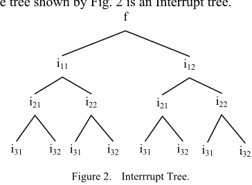
B. Drawing an Interrupt Tree
Definition 2. Given a tree T. The tree T is called an Interrupt tree if it satisfies the following four conditions.
a)The root is one of page nodes of Function tree. Each non-root node is on behalf of an interrupt. The priority of the parent is higher than that of any child node, the priorities of brother nodes are the same.
b)The weight of the root is the capacity of the stack for storing the parameters, the local variables, the return address of the function, the breakpoint and the breakpoint data.
c)The weight of non-root and non-page node is the capacity of the stack for storing the parameters, the local variables, the breakpoint, and the breakpoint data of the ISR, and the parameters, the return addresses, the local variables of the functions called by the ISR.
d)The weight of page node is the capacity of the stack for storing the local variables of the ISR and the parameters, the returning addresses, the local variables of the functions called by the ISR directly or indirectly.
The tree shown by Fig. 2 is an Interrupt tree.
Figure 2. Interrrupt Tree.
In the Interrupt tree shown by Fig. 2, there are three level of interrupt. The priority of i31 and i32 is the
f23
f21 f22
f11 f12
t
f33
f31 f32
f41 f42
i22 i21
i11 i12
f
i32 i31 i32 i31
i22 i21
highest. The priority of i21 and i22 is next. The priority of i11 and i12 is the lowest.
The Interrupt tree shown by Fig. 2 describes eight nests of interrupts. i11→i21→i31 is one of them. So, an Interrupt tree can be used to calculate the maximal requirement of the nested interrupts for capacity of the task stack.
Based on Function tree and Interrupt tree, a new tree structure can be defined.
C. Drawing an Extreme Tree
Definition 3. Given a tree T. The tree T is called an Extreme tree if it satisfies the following two conditions.
a)It is composed of one Function tree and some Interrupt trees.
b)For each page node of the Function tree, there exits an Interrupt tree whose root is the page node.
For all Interrupt trees in an Extreme tree, only their root nodes are different.
The tree shown by Fig. 3 is an Extreme tree. It is composed of one Function tree and three Interrupt trees. The dotted line frame inner is a Function tree, the real line frame inner is an Interrupt tree.
Figure 3. Extreme Tree.
An Extreme tree has various paths from the root node to page nodes. Every path in Extreme tree represents a possibility that the task uses he stack extremely. So, there are 12 possibilities of using stack extremely for the task corresponding to the Extreme tree shown by Fig. 3.
D. Determining Weights of all Nodes in Extreme Tree By Def. 1, the weight of the root is the capacity of the stack for storing the parameter pointer and the local variables of the task.
By Def. 1, the weight of non-root and non-page node in Function tree is the capacity of the stack for storing the parameters, the local variables and the return address of the function.
By Def. 1 and Def. 2, the weight of the page node in Function tree or the root node in Interrupt tree is the capacity of the stack for storing the parameters, the local variables, the return address of the function, the breakpoint and the breakpoint data.
By Def. 2, the weight of non-root and non-page node in Interrupt tree is the capacity of the stack for storing the parameters, the local variables, the breakpoint, and the
breakpoint data of the ISR, and the parameters, the return addresses, the local variables of the functions called by the ISR.
By Def. 2, the weight of page node is the capacity of the stack for storing the local variables of the ISR and the parameters, the returning addresses, the local variables of the functions called by the ISR directly or indirectly.
After determining weights of all nodes in Extreme tree, a table which contains all nodes and their weights can be listed, it is shown by Tab II.
E. Calculating Weights of all Paths from Root to each Page Node
Definition 4. In an Extreme tree, the weight of a path from the root to a page node is the sum of the weights of all nodes in the path.
Assume that the paths from root to each page node are Pl, P2, P3, ..., Pj, ....
By Def. 4, the weight of a path can be calculated with following formula.
Wj =
∑
=n
i i
w
1
(1)
Where, Wj is the weight of path Pj, n is the number of nodes on path Pj, wi is the weight of node No. i on path Pj.
When CPU runs along path Pj, the size of stack required by the task is Wj. So Wj reflects the usage of stack space at an extreme case.
In the Extreme tree shown by Fig. 3, there are twelve paths from the root node to page nodes, shown by Tab. II.
F. Determining Maximum Stack Space required by Task In weights of all paths, there exists a maximum value. It is the most capacity needed by the task. The maximum value can be calculated with following formula.
MW=max {W1,W2,W3,…,Wj,…} (2) f22
f21
f11 f12
t
i12 i11
i22
i21 i21 i22
i12 i11
i22 i21 i21 i22
i12 i11
i22
i21 i21 i22
TABLE II. PATHS OF EXTREME TREE
Name of Path Path
P1 t → f11 → f21 → i11 → i21
P2 t → f11 → f21 → i11 → i22
P3 t → f11 → f21 → i12 → i21
P4 t → f11 → f21 → i12 → i22
P5 t → f11 → f22 → i11 → i21
P6 t → f11 → f22 → i11 → i22
P7 t → f11 → f22 → i12 → i21
P8 t → f11 → f22 → i12 → i22
P9 t → f12 → i11 → i21
P10 t → f12 → i11 → i22
P11 t → f12 → i12 → i21
Where, MW represents the maximum one in weights of all paths, max refers to calculate maximum one from weights of all paths, Wj is the weight of path Pj which is calculated with Tab. III and (1).
The maximum weight, that is MW, is in fact the maximum size of stack, which is required by the task.
As long as MW is determined as the capacity of the task stack, the task can be guaranteed the demand for the stack space in any cases.
IV. APPLICATION
The approach of calculating the capacity of µC/OS-II task stack has been applied to the design of a circuit breaker controller. The circuit breaker controller is used to control turning on and turning off of circuit breakers. It is designed based on LPC2138 CPU and µC/OS-II operating system. Its application software is divided into five tasks, which are turning-on task, turning-off task, receiving-data task, sending-data task and control task. In this Section, turning-on task is taken as an example to describe application of the approach above.
A. Function Tree of Turning-on Task
Function tree of a µC/OS-II task is drawn according to the source code of the task and the source code of µ C/OS-II operating system. Turning-on task is named OnTask(), its source code is following.
void OnTask(void *pdata) {
extern uint8 OnCon;
PINSEL1=PINSEL1&(~(0x03<<10)); IO0DIR=IO0DIR|(1<<21);IO0SET=1<<21; while(1)
{
if(OnCon ==1) {
IO0CLR=1<<21; OnCon =0; }
OSTimeDly(10); }
}
Turning-on task calls a µC/OS-II function named OSTimeDly(). According to the source code of µC/OS-II operating system, the function OSTimeDly() calls another
µC/OS-II function OS_Sched(). Therefore, there is nest of functions. The Function tree corresponding to the nest of function can be described by a Function tree. Function tree of turning-on task is shown by Fig. 4.
Figure 4. Function Tree of Turning-on Task.
In Function tree of turning-on task, there are three nodes, the root node represents turning-on task, OSTimeDly() node represents a function called by turning-on task, OS_Sched() represents a function called by OSTimeDly().
In Function tree of turning-on task, a parent node has only one child node. There is only one page node, that is, OS_Sched().
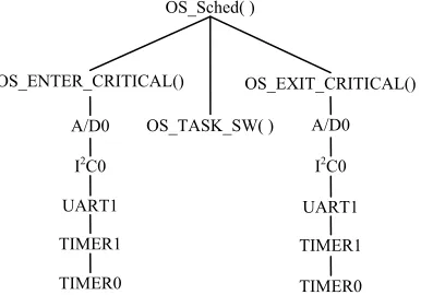
B. Interrupt Tree of Turning-on Task
Function tree of turning-on task has only one page node, so there is only one Interrupt tree for turning-on task.
In Function tree of turning-on task, OS_Sched() calls OS_ENTER_CRITICAL(), OS_EXIT_CRITICA() and OS_TASK_SW(). OS_ENTER_CRITICAL() is used to close interrupt, OS_EXIT_CRITICA() is used to open interrupt, OS_TASK_SW() is used to switch task. Their implementation is related to the CPU. In the source code which ports µC/OS-II operating system to ARM7 CPU[8], these macros are implemented by using software interrupt. Therefore, the three macros are the lowest priority interrupt. OS_TASK_SW() executes in critical section, so it does not respond to higher interrupt. The other two software interrupts may respond to higher priority interrupt during executing.
In circuit breaker controller system, five IRQ interrupts source are used. By priority from low to high, they are A/D0, I2C0, UART1, TIMER1 and TIMER0. A/D0 is A/D converter 0. I2C0 is I2C serial interface 0. UART1 is universal asynchronous receiver/transmitter 1. TIMER1 is timer 1. TIMER0 is timer 0[9].
In the most extreme cases, OS_Sched() is interrupted by OS_ENTER_CRITICAL() or OS_EXIT_CRITICA(), OS_ENTER_CRITICAL() or OS_EXIT_CRITICA() is interrupted by A/D0, the ISR of A/D0 is interrupted by I2C0, the ISR of I2C0 is interrupted by UART1, the ISR of UART1 is interrupted by TIMER1, the ISR of TIMER1 is interrupted by TIMER0. Therefore, there is a nest of interrupts in this system. The nest of interrupts can be described by an Interrupt tree. Interrupt tree of turning-on task is shown by Fig. 5.
In Interrupt tree of turning-on task, there are 14 nodes. The root node that is OS_Sched() is the page node of Function tree of turning-on task. Each non-root node is on behalf of an interrupt source and the priority of the parent is higher than that of any child node. There are three brother nodes, their priorities of interrupt are the same.
Figure 5. Interrupt Tree of Turning-on Task. OS_Sched( )
OSTimeDly( ) OnTask
OS_Sched( )
OS_TASK_SW( )
OS_ENTER_CRITICAL() OS_EXIT_CRITICAL()
A/D0
I2C0
UART1
TIMER1
TIMER0
A/D0
I2C0
UART1
TIMER1
C. Extreme Tree of Turning-on Task
By Def. 3, the extreme tree of turning-on task can be drawn, shown by Fig. 6.
Figure 6. Extreme Tree of Turning-on Task.
It is composed of Fig. 4 and Fig. 5.
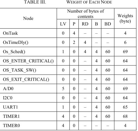
D. Weights of all Nodes in Extreme Tree
LPC2138 is 32 bit CPU, so the size of breakpoint or return address is 4 bytes. Breakpoint data contains the backup of 14 CPU registers and Interrupt Counter OsEnterSum, so 60 bytes of storage space is needed to store the breakpoint data [8].
By Def. 1, the weight of OnTask is the sum of sizes of the parameter pointer and the local variables of OnTask. OnTask has not local variable. The size of parameter pointer of OnTask is 32 bits [8]. So, the weight of OnTask is 4 bytes.
By Def. 1, the weight of OsTimeDly() is the sum of sizes of the parameters, the local variables and the return address of the function. OsTimeDly() has not local variable. The size of parameters of OsTimeDly() is 2 bytes. The size of parameters of return address is 4 bytes [8]. So, the weight of OsTimeDly() is 6 bytes.
By Def. 1 and Def. 2, the weight of Os_Sched() is the sum of sizes of the parameters, the local variables, the return address, the breakpoint and the breakpoint data. Os_Sched() has not parameter. The size of local variable is 1 byte. The size of the return address is 4 bytes. The size of the breakpoint is 4 bytes [8]. The size of the breakpoint data is 60 bytes [8]. So, the weight of Os_Sched() is 69 bytes.
By Def. 2, the weight of OS_ENTER_CRITICAL() is the sum of sizes of the parameters, the local variables, the breakpoint, and the breakpoint data of the ISR, and the parameters, the return addresses, the local variables of the functions called by the ISR. This macro has not parameter and local variable, it does not call any functions also. The size of the breakpoint is 4 bytes. The size of the breakpoint data is 60 bytes. So, the weight of OS_ENTER_CRITICAL() is 64 bytes.
The determining of the weights of other nodes including five IRQ interrupt nodes is similar. The weights of other nodes are shown by Tab. III.
In Tab. III., column LV refers to local variable, P refers to parameter, RD refers to return address, B refers to breakpoint, BD refers to breakpoint data.
E. Weights of all paths and Maximum Stack Space In extreme tree of turning-on task, there are three different paths from left to right, shown by Fig. 7.
Figure 7. All paths of of turning-on task.
By (1), W1 that is the weight of P1 is 413 bytes, W2 that is the weight of P2 is 143 bytes and W3 that is the weight of P3 is 413 bytes. So, by (2), the stack size of turning-on task should be 413 bytes.
V. CONCLUSION
The difficulty to determine the size of µC/OS-II task stack is to determine the capacities needed by functions and interrupts. When the deepest nest of functions occurs, the functions will take up more stack space. Similarly, when the deepest nest of interrupts occurs, the interrupts will take up more stack space. In this paper, Function tree is defined to describe the deepest nest of functions. Interrupt tree is defined to describe the deepest nest of
OS_Sched( )
OS_TASK_SW( )
OS_ENTER_CRITICAL() OS_EXIT_CRITICAL()
A/D0
I2C0
UART1
TIMER1
TIMER0
A/D0
I2C0
UART1
TIMER1
TIMER0 OSTimeDly( )
OnTask OS_Sched( )
OSTimeDly( ) OnTask
OS_Sched( ) OSTimeDly( )
OnTask
(a) P1 (b) P2 (c) P3
OS_Sched( )
OS_TASK_SW( )
OS_ENTER_CRITICAL() OS_EXIT_CRITICAL()
A/D0
I2C0
UART1
TIMER1
TIMER0
A/D0
I2C0
UART1
TIMER1
TIMER0 OSTimeDly( )
OnTask
TABLE III. WEIGHT OF EACH NODE
Node
Number of bytes of
contents Weights (byte) LV P RD B BD
OnTask 0 4 – – – 4
OsTimeDly() 0 2 4 – – 6
Os_Sched() 1 0 4 4 60 69
OS_ENTER_CRITICAL() 0 0 – 4 60 64
OS_TASK_SW() 0 0 – 4 60 64
OS_EXIT_CRITICAL() 0 0 – 4 60 64
A/D0 5 0 – 4 60 69
I2C0 0 0 – 4 60 64
UART1 1 0 – 4 60 65
TIMER1 4 0 – 4 60 68
interrupts. Based on Function tree and Interrupt tree, Extreme tree is defined to describe all the possibilities of the task using extremely stack. Among of all the possibilities, there is always a case that the task needs maximum stack space. The approach described by this paper is to find the case and to calculate this demand for stack space. Because the demand is maximum, as long as it is set to the task stack size, requirements for stack space in any case can be met.
REFERENCES
[1] Jean J. Labrose, MicroC/OS-II the real-time kernel, 2nd ed.,Beijing University of Aeronautics and Astronautics Press, Beijing China, 2003, pp.125–126.
[2] S.J. Yang,and H.S. Li, “Improved design of µC/OS-II Task-stack handle”. Microcontroller & Embedded systems, Beijing China, 2004, pp.73-74.
[3] Yue Chen, Linglin Xia, Tian Zhang. “Optimization of
stack structure based on µC/OS-II”. Computer
Applications and Software, Shanghai China, 2009, vol. 26, pp.246-247.
[4] Liangqing Peng. “A improvement approach of µC/OS-II task stack”. Microcontroller & Embedded systems, Beijing China, 2003, pp.20-22
[5] Daniel W. Lewis. Fundamentals of embedded software,
Higher Education Press, Beijing China, 2005, pp.151-163
[6] Y.Q. Li, X.D. Wang, and Z. Li. “Research of a tree
structure based fully automatic wrapper method”. Journal
of Hebei University of Technology, Tianjin China, 2007,36 , vol. 6, pp.41-46.
[7] H.S. Yu, and Y.N. Wang, “Efficient stereo-image feature detection algorithm based on tree structure”, Computer Applications, Chengdu China, 2004,24, vol. 10, pp.78-81. [8] Z. Ren, Embedded real time operating system µC/OS-II
principles and applications, Beijing University of Aeronautics and Astronautics Press, Beijing China, 2005, pp.208–222.
[9] Philips Semiconductors. LPC2131/2132/2138 Single-chip 16/32-bit microcontrollers, Koninklijke Philips Electronics N.V. 2004, pp.1–36.
Guangjian Zhang was born in Chongqing, China, in March, 1970. He holds the Master’s degree of engineering from Guizhou University, China, in July, 2004.
Before 2001, he was an electrical Engineer. Now, he is an associate professor of School of Computer Science and Engineering, Chongqing University of Technology, Chongqing, China. His current research interest is embedded software.
Zheng Liu was born in Sichuan, China, in December, 1969. He holds the Master’s degree of engineering from Chongqing University, China, in June, 2002.