http://www.sciencepublishinggroup.com/j/sr doi: 10.11648/j.sr.20170503.14
ISSN: 2329-0935 (Print); ISSN: 2329-0927 (Online)
Study of Vertical Variation Regularity of Horizontal Soil
Arching Height Along Pile Length
Dengfeng Li
1, Xiewen Hu
1, Xiaoyan Zhao
1, *, Jingwu Zhang
2, Victor Maicolo Nhansumba
11Department of Geology Engineering, Southwest Jiaotong University, Chengdu, China
2
School of Earth Sciences and Engineering, Hohai University, Nanjing, China
Email address:
[email protected] (Dengfeng Li), [email protected] (Xiewen Hu), [email protected] (Xiaoyan Zhao), [email protected] (V. M. Nhansumba), [email protected] (Jingwu Zhang)
*Corresponding author
To cite this article:
Dengfeng Li, Xiewen Hu, Xiaoyan Zhao, Jingwu Zhang, Victor Maicolo Nhansumba. Study of Vertical Variation Regularity of Horizontal Soil Arching Height Along Pile Length. Science Research. Vol. 5, No. 3, 2017, pp. 44-49. doi: 10.11648/j.sr.20170503.14
Received: June 25, 2017; Accepted: July 20, 2017; Published: August 7, 2017
Abstract:
Stabilizing piles are now considered one of the most effective measures of enhancing the stability of landslides, the horizontal soil arching effect has an important influence on the force of the structure between piles. Until now, the variation of the soil arching height along pile length is not considered in practice, and the variation which can affect the force of stabilizing piles and the structures between piles. This paper presents the numerical simulation to analyze the law of the variation of soil arching height along pile length. The results show that (a) the height of the soil arching decreases monotonously along pile length; (b) the position of the soil arching appears above sliding surface and under the pile-top; (c) the soil arching effect cannot be considered under the sliding surface.Keywords:
Stabilizing Piles, Soil Arching Effect, Numerical Simulation, Soil Arching Height1. Introduction
In China many people live around mountainous areas and with the development of railway and highway construction projects around those areas, in recent years, more and more residents have to face with the landslide threats. As a result, stabilizing piles combined with other structural measures have been developed for the treatment of slope instabilities, which in nowadays practice of slope reinforcement its common the use of stabilizing piles across the active or potential failure surface, combined with other soil retaining structures, such as gravity walls, cantilever walls or soil nail walls between piles and it is proven that soil arching effect is the key factor that affect the load distribution against the composite retaining structure [1]. Therefore, many researchers have done a lot of studies on soil arching. Such as, Kahyaoglu et al. [2] using a high-speed camera have successfully captured the displacement of the soil behind the stabilizing piles, which confirmed the existence of the soil arching effect. Pardo et al. [3] through numerical simulation and laboratory model tests have reproduced the
example, Li et al. [9], have proposed the formula for calculating the spacing of piles using a mechanical model of the soil behind the piles. Yang et al. [10] through the centrifugal model test, analyzed the influence of stabilizing pile width and spacing on the soil arching effect. Zhao et al. [11] based on the theory of soil arching, proposed a formula for the calculation of the spacing for circular cross-section of stabilizing piles.
However, studies on the method of quantification of the load against the retaining structure between the stabilizing piles based on the theory soil of arching effect are still scarce. Actual in the above studies the calculation of the load acting against the retaining structure between the stabilizing piles is done using the following methods: (1) by directly using the coulomb active earth pressure theory without considering the soil arching effect; (2) estimating
the earth pressure using the wall height and the soil gravity; (3) by using the coulomb active earth pressure and increasing the soil strength parameters of cohesion and internal friction of the soil, in order that the active earth pressure against the retaining wall is reduced, for example some railway design codes my recommend to increase the internal friction angle of the soil by 5° [12]; (4) by using the coulomb active earth pressure and multiplying it with a reduction coefficient of 0.7~0.8 [13]; (5) the pressure of the board load refer to the pressure of the load-off arching when considering the plate between piles flexibility. To a certain extent the above calculation method have recommended the application of the theory of soil arching to engineering problems, but they does not consider the variation of soil arching height along the pile length.
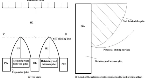
Figure 1. Sketches of the combination of stabililzing piles and retaining walls and soil arching.
The variation of the soil arching height with the pile length leads to the variation of the load distribution against the retaining structure between piles [14]. Figure 1(a), illustrate the force acting on the composite structure of stabilizing piles combined with retaining wall between piles, when the variation of the soil arching height along the pile length is considered, the earth pressure acting on retaining wall between piles is produced by the sliding soil in front of the soil arching, as shown in Figure 1(b), will be different for example from that calculated by using the Swedish slice method combined with the theory of soil arching when the arching height is taken as constant along the pile length.
The main purpose of this paper is to study the variation of soil arching height along the pile length using numerical simulation method, thus making a helpful contribution to the
improvement of the theory of soil arching, that will make the design of composite structures (stabilizing piles combined with retaining wall between piles) more practical, when the soil arching effect is considered.
2. Numerical Simulation of Soil Arching
Height Variation
2.1. Model Building
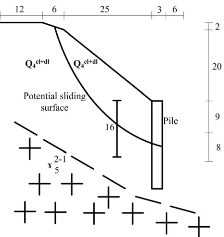
and soil material, which could better reproduce the soil arching effect under the action of landslide thrust. In this study the slope D 1K 70+360 ~ DK 70+390 along the railway between Dazhou to Bazhong (on the right side) is taken as an example slope. Since the slope is to a tunnel exit that is narrow and steep, so is not suitable for unloading treatment through excavation, thus stabilizing piles were recommended as initial design measures for the slope reinforcement. The landform of the region is composed of low mountains/hills, its ground elevation is about 270 ~ 480m, the relative height difference is about 30 ~ 120m, the natural slope gradient vary between 10° ~ 40°, partially steep, with ravine features on the left and the right; the slopes has lush vegetation and the topography of the intermountain terrain is relatively flat, also it has paddy fields with ravine developments, the slope mass is mainly composed of heavily weathered mudstone of residual soil layer with 60m thick. The geological profile is shown in Fig. 2
Figure 2. Slope geometry and geologic profile in (m).
2.2. FLAC 3 D Numerical Model
The FLAC 3 D numerical model with its corresponding dimensions and boundary conditions are shown in Fig. 3, with slope stabilizing piles installed on the right side of the railway grade on the slope, the outer boundaries of the model are restrained in both sides of the horizontal direction of x-axis and y-axis and the bottom is also restrained in the xyz directions, the direction of x-axis is parallel to the dip direction of the slope, the direction of y-axis parallel to the strike direction of slope and the z-axis is in the same
direction as the slope height (defined as the positive in the vertical upward direction), where X, Y, Z meet the right hand rule.
Figure 3. FlAC 3 D numerical model profile in (m).
In order to study the variation of soil arching height along the pile length, a FEM numerical simulation model is built. The quadrilateral meshes are used in the FEM model. In this model, the stabilizing pile section size is 2 m × 3 m (width × height) and 16 meters in length is selected, with a center-to-center distance of 7 meters, the width of the slope is 13 meters considering the boundary effect. The FLAC 3 D three-dimensional model is shown in Fig. 4. The FLAC 3 D software is used to conduct the numerical modeling, the stabilizing piles are assumed to obey the elastic model and the slope soil mass is considered as a Mohr-Coulomb material, the physical and mechanical parameters of the stabilizing pile and the soil mass are shown in Table 1.
Figure 4. FLAC 3 D three-dimensional model.
Table 1. Physical and mechanical parameters of stabilizing piles and soils.
Material Unit Weight (Kn. m-3) Bulk Modulus (kPa) Shear Modulus (kPa) Cohesion (kPa) Internal friction angle (°)
Soil 17.5 5×10⁴ 2.31×10⁴ 24 35
2.3. Soil Arching Formation Mechanism and Classification
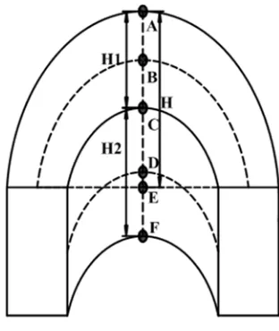
Due to the presence of soil arching effect the driving force caused by the landslide mass will be redistributed to stabilizing pile, thus the driving force could act on the back wall or the sidewall of the stabilizing piles. As shown in Figure 5, the soil arching is divided into the end-bearing arching and the friction arching [15], that are referred as a separate soil arching [16], therefore, the end-bearing arching means that the driving force transferred through the soil arching to the stabilizing pile is concentrated on the backwall of the pile, as shown in Figure 5, height of the end-bearing arching is H 1, in Figure 5 point A, B and C represent the upper vertex of outer line of end-bearing soil arching, the vertex of axis line of the end-bearing soil arching, the lower vertex of the inner line of end-bearing soil arching or the upper vertex of the outer line of end-bearing soil arching respectively. The soil arching between the piles is referred to as the friction arching, which is formed when the driving force transferred to the stabilizing piles concentrated on the sidewall of the piles, the height of the friction arching is H 2. Point D, E and F represent the vertex of axis line of friction arching, the middle point of the pile back connection, the vertex of the inner line of frition arching respectively. Therefore, the slope driving force is first transferred through the soil arching to the back wall of the stabilizing piles and forms a stable body with end-bearing arching. When failure occurs to the end-bearing arching, the slope driving force will be concentrated on the sidewall of piles, forming a
friction arching to stabilize the landslide.
Figure 5. Classification of soil arching.
3. Discussion on Soil Arching Height
Variation Along the Pile Depth
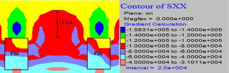
Since the impact of the driving force is greater in X-direction, then the variation of the soil arching height will be studied using the x-direction stress contour (SXX). As shown in Figure 6, four typical stress contours in horizontal planes are selected for the study purpose.
(a) Horizontal stress contour at 1.0m below the pile top in the x-direction
(c) Horizontal stress contour at 7.0m below the pile top in the x-direction
(d) Horizontal stress contour at 8.0m below the pile top in the x-direction
Figure 6. Horizontal stress contours at different depths from the top of the pile in the x-direction.
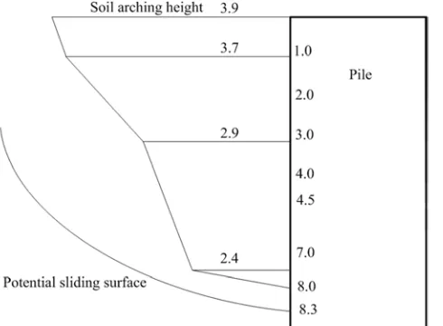
As shown in Fig. 6(a), among the four previously selected sections the position of the highest soil arching height (about 3.7m) is located at a depth of 1.0m below the top of the pile, and the outer arch vertex is located on the back wall of piles. It can be seen that the slope driving force is concentrated on the back wall of the stabilizing piles, in this case the soil arching is end-bearing arching. From Fig. 6(b), it can be observed that the position of the second highest soil arching is 3.0m below the top of the piles, the location of the outer arching edge is the same as above, which means that the soil arching also is the end-bearing arching. The soil arching height is smaller than 3.0m at a depth of 7.0m below the top of the piles, and Figure 6(c), shows that the outer arch vertex is located on the sidewall of piles, indicating that the slope driving force is concentrated on the pile side face, in this case the soil arching is considered as friction arching. The critical depth between the end-bearing arching and friction arching is 5.8m below the piles. Figure 6(d) illustrates that the potential failure surface of the slope is located at a depth of 8.3m from the top of the pile, indicating that the soil arching appears only above the potential failure surface under the top of piles, thus the soil arching height of the outer arch decreases monotonously with the pile depth. According to the numerical simulation results, some conclusions are as follow: The driving force from the slope is transferred to the stabilizing piles through the soil arching, and with the
increase of the depth of piles, the slope driving force concentrate on the back wall of the pile to form the end-bearing arching that stabilize the unstable soil mass. Nevertheless, when the end-bearing arching failure occurs, the slope driving force will be concentrated on the pile side, through the friction arching to stabilize the unstable soil mass. The variations of the outer-arching height along the direction of the pile length are shown in Fig. 7.
Figure 7. Soil arching height at different depths.
4. Conclusions
The horizontal soil arching of mudstone residual soil slope appears only above the slope failure surface under the top of the pile, and the soil arching is not considered under the failure surface, and the soil arching height decreases monotonously with the increase of the pile depth.
The slope driving force is transferred to the stabilizing through the soil arching, along the depth of the pile the driving force is concentrated on back wall of the stabilizing pile, leading to the formation of end-bearing arching, which in turn decrease with the increase in depth of the stabilizing piles, in this way the driving force is gradually transferred to the stabilizing pile through the friction arching, and the results of this study can be applied to the mudstone or granite residual soil, that is, the slope soil material should obey the Mohr-Coulomb criterion. If the soil does not satisfy the Mohr-Coulomb criterion, the variation law of the soil arching height should be studied further.
References
[1] X. Y. Zhao, J. W. Zhang and Y. Liang, et al. “Design method for combined active/passive anchoring for granitoid soil slope,” Chinese Journal of Rock Mechanics and Engineering Vol. 32, No. 3, 2013, pp. 633-639.
[2] Mehmet, R K., Okan O., Gökhan I., et al. “Soil arching and load transfer mechanism for slope stabilized with piles,” Journal of Civil Engineering & Management Vol. 18, No. 5, 2012, pp. 701-708.
[3] G. S. Pardo and E. Sáez, “Experimental and numerical study of arching soil effect in coarse sand. Computers and Geotechnics,” Vol. 57, No. 4, 2014, pp. 74-84.
[4] R. S. Dalvi and P. J. Pise, “Analysis of Arching in Soil-Passive
State,” Indian Geotechnical Journal, Vol. 42, No. 2, 2012, pp. 106-112.
[5] M. G. Li, J. J. Chen, and J. H. Wang, “Arching effect on lateral pressure of confined granular material: numerical and theoretical analysis. Granular Matter,” Vol. 19, No. 2, 2017, pp. 20.
[6] Y. Cai, Q. Chen and Y. Zhou, et al “Estimation of Passive Earth Pressure against Rigid Retaining Wall Considering Arching Effect in Cohesive-Frictional Backfill under Translation Mode,” International Journal of Geomechanics, 2016.
[7] X. Y. Zhao, B. WU, and D. F. LI, et al “Load calculation for retaining wall between piles basing on horizontal soil arch effect,” Chinese Journal of Geotechnical Engineering, 2016, pp. 811-817.
[8] P. Jing and M. W. Li, “Simplified Method for Calculating Active Earth Pressure on Rigid Retaining Walls Considering the Arching Effect under Translational Mode.,” International Journal of Gemechanics, Vol. 14, No. 2,2014, pp. 283-292.
[9] S. J. Li, J. Chen and C. Lian, “Mechanical model of soil arch for interaction of piles and slope and problem of pile spacing,” Rock and Soil Mechanics, Vol. 31, No. 5, 2010, pp. 1352-1358.
[10] M. YANG, L. K. Yao, and G. J. Wang, “Study on effect of width and space of anti-slide piles on soil arching between piles. Chinese Journal of Geotechnical Engineering,” Vol. 29, No. 10, 2007, pp. 1477-1482.
[11] M. H. Zhao, Y. H. Chen, and C. W. Yang, “Methods for determining rational spacing between anti-slide piles considering soil arching effects. Chinese Journal of Geotechnical Enginee,” Vol. 37, No. z 2, 2015, pp. 16-21.
[12] Second Railway Survey and Design Institute. Railway embankment design of retaining structures [S]. BeiJing: China railway publishing house, 2006. (in Chinese).
[13] M. G Krein, “Structural mechanics of grain material”. Beijing: China communication press, 1983. (in Chinese translated by CHEN Wan-jia).
[14] D. F. LI, X. W. Hu, and X. Y. Zhao et al, “Variation of horizontal arch height of granite residual soil slope invertical direction,” Journal of Southwest Jiaotong University, Vol. 51, No. 5, 2016, pp. 1024-1032.
[15] C. Li, H, Tang, and X. Hu et al, “Numerical modelling study of the load sharing law of anti-sliding piles based on the soil arching effect for Erliban landslide,” China. KSCE Journal of Civil Engineering, Vol. 17, No. 6, 2013, pp. 1251-1262.
[16] Z. P. Lin, Z. Q. Liu, and Q. T. Shang, “Research on soil arch of anti-slide pile structure with methods of separation and combination,” Rock and Soil Mechanics, Vol. 33, No. 10, 2012, pp. 3109-3114.