http://www.sciencepublishinggroup.com/j/ajae doi: 10.11648/j.ajae.20160303.14
ISSN: 2376-4813 (Print); ISSN: 2376-4821 (Online)
Electrodynamic Launch System Takeoff-Elevating
Platforms for Deck-Based Aircraft Carriers Concept
Development and Design
Volodymyr Chumakov, Oleksandr Stolarchuk
Independent Scholar, Kharkiv, Ukraine
Email address:
[email protected] (V. Chumakov)
To cite this article:
Volodymyr Chumakov, Oleksandr Stolarchuk. Electrodynamic Launch System Takeoff-Elevating Platforms for Deck-Based Aircraft Carriers Concept Development and Design. American Journal of Aerospace Engineering. Vol. 3, No. 3, 2016, pp. 43-49.
doi: 10.11648/j.ajae.20160303.14
Received: December 3, 2016; Accepted: December 22, 2016; Published: January 7, 2017
Abstract:
The results of the development of the deck-based takeoff-elevating platforms of electrodynamic launch system are given. The research results of electrodynamic railguns with pulsed-dynamic biasing of acceleration channel and their modifications are used as the basis for the development and design. Comparative characteristics of the developed systems EMALS criteria are shown.Keywords:
Electromagnetic Aircraft Launch System, Coaxial Electrodynamic Railgun, Pulse-Dynamic Biasing System, Rotor, Traction Force1. Introduction
The perspective launch system from the deck of the aircraft carrier "Gerald R. Ford” with the electromagnetic catapults (Electromagnetic Aircraft Launch System-EMALS) is widely covered by the media. Having sufficient experience in the design of electrodynamic accelerators, as the example of their practical application, our authors team proposed the concept of a design embodiment of the electrodynamic launch system for deck-based takeoff-elevating platforms based on electrodynamic railgun (EDRG) with the distributed pulse-dynamic biasing system (PDBS) [1–4]. EMALS requirements were taken as the initial data, published in [5, 6]. It should be noted that in recent years the EMALS development is becoming increasingly relevance [7, 8].
According to the technical specifications EMALS should provide the following parameters of the aircraft launch:
ultimate velocity of the aircraft-28-102,8 m/s; deviation of traction (strain)-less than 5%; energy of launch aircraft-122 MJ;
duration of the cycle starts-45 s; system weight–less 225 tonn;
system volume (overall dimensions)-less 425 m3; max. aircraft final velocity deviation-±1.5 m/s.
Calculation of EDRG parameters was carried out for the hardest regime of the start-the maximum mass of the aircraft is launched with a minimum track length:
minimal track length–91 m; starting aircraft mass–40 000 kg; final velocity–300 km/h.
To gather velocity from 0 to 300 km/h at a track length of 91 m, the aircraft should move with an acceleration of about 38 m/s2. For further evaluation the value of acceleration was accepted of 40 m/s2. Besides for the given acceleration regime of the aircraft at a weight of 40 tons, the EDRG catapult rotor should develop a traction force of 1.6 MN. Calculations of various railgun modifications have been carried out precisely for this value of traction [9].
simplifies the issue of electromagnetic compatibility with the rest of the onboard equipment, as well as the impact on the avionics of the aircraft and its hanging system [10, 11].
2. Simulation of Rotor Movement Along
Acceleration Channel for Different
EDRG Designs
To select the optimal design of electrodynamic accelerator for EMALS and determine the completeness of its conformity with requirements specification, simulation modeling of the rotor motion along acceleration channel of raiguns with five different embodiments of the PDBS cells was carried out. Special attention was paid to the points of docking coils.
The 3D models of the EDRG section in which the rotor moves in the acceleration channel in increments of 50 mm were calculated. Simulated sections had constant and variable parameters.
1. Constant parameters:
length of the accelerator section-2000 mm;
inner diameter of the acceleration channel-500 mm; density coil in the biasing coil-57 A/mm2.
2. Variable parameters:
current in the bus pairs (rails);
number of ampere-turns in one biasing section.
The aim of the calculation is to determine variable parameters, which provide the average value of the traction not less than 1.6 MN and the value of the traction deviation as well.
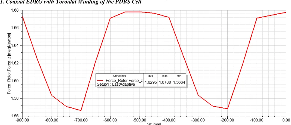
2.1. Coaxial EDRG with Toroidal Winding of the PDBS Cell
The first modification to be calculated was the coaxial EDRG with toroidal winding cell of PDBS (Figure 1).
Figure 1. The Coaxial EDRG with toroidal winding of the PDBS cell.
In this structure of the coaxial railgun the PDBS cell is a quarter segment of a torus, which fills a quadrant between the horizontal and vertical bus pair of power rail. Installed one stage four segments of PDBS cells form a torus, divided into four narrow grooves.
Toroidal magnet system generates a magnetic field inside these grooves at the moment when the rotor blades pass through them. During the simulation, the length of the biasing cell in this design of coaxial EDRG was taken to be 500 mm.
The calculation showed that to develop the average value of the rotor traction at least 1.6 MN, bus pairs need to be powered by the current of 670 kA. Each of the biasing system section consists of 490 kA×turns. Distribution of the rotor traction force along the acceleration channel is shown in Figure 2.
Figure 2. Rotor traction force distribution along the acceleration channel for coaxial EDRG with toroidal winding of PDBS cell.
As a result of postprocessing, the following data were obtained, to use it in further analysis: Fmax-maximum traction
of the rotor, MN; Fmin-minimum traction of the rotor, MN;
Favg-average value of the traction of the rotor, MN.
Traction deviation was determined as:
max min 100%
avg
F F
d F
−
For coaxial EDRG with the toroidal winding of the PDBS cell, the value of traction deviation is 6.8%, that does not meet the technical requirements EMALS.
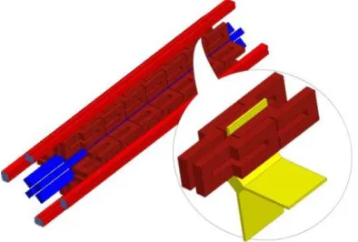
2.2. Coaxial EDRG with Plane Straight PDBS Cells
The second modification to be calculated was the coaxial EDRG with plane straight PDBS cells (Figure 3).
Figure 3. The Coaxial EDRG with plane straight PDBS cells.
In addition to the unsatisfactory value of the deviation of
rotor traction, toroidal shape of the biasing coil has a number of significant drawbacks. It is primarily the maximum coil mass due to fill the entire volume in the quadrant between the horizontal and vertical bus pair as well as an increased consumption of the winding material (copper bus), and, correspondingly, its price. To reduce the weight and cost of the PDBS the use of a plane shape of biasing coil was considered. In this structure the PDBS cell is a pair of straight plane coils which are disposed on both sides under the bus pair. The gap between the biasing coils coincides with a gap formed by the bus pair, wherein the rotor blade moves. During the simulation, the height of the coil winding was chosen to be as maximal as possible, based on the limitations imposed by the design of the accelerator, and the length of the biasing cell was taken to be 350 mm.
The calculation showed that to develop the average value of the rotor traction at least 1.6 MN, bus pairs need to be powered by the current of 670 kA as well. Each of the biasing system section consists of 228 kA×turns. Distribution of the rotor traction force along the acceleration channel is shown in Figure 4.
Figure 4. Rotor traction force distribution along the acceleration channel for coaxial EDRG with plane straight PDBS cell.
For coaxial EDRG with plane straight PDBS cell, the value of traction deviation is 6.8%, that does not correspond the technical requirements EMALS.
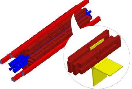
Figure 5. Coaxial EDRG with plane stepped PDBS cells.
2.3. Coaxial EDRG with Plane Stepped PDBS Cells
Further research led to the development of the сoaxial EDRG with plane stepped PDBS cells (Figure 5) for which calculations were made.
a partial mutual compensation of the magnetic field. To reduce the negative effect of mutual compensation of the magnetic field on the value of the deviation of the rotor traction, the coil is designed in such a way that adjacent cells could overlap each other by 50%. This design allows to spread the winding elements maximally with oppositely directed currents and to distribute them along the path of the rotor motion.
In this structure of the coaxial EDRG, the biasing coil is a plane winding with the stepped overfall in the middle of the stairs in the direction of the magnetic field lines vector. PDBS cell is formed by a pair of stepped coils, which are
located on both sides under the bus pair. The gap between the biasing coils coincides with a gap formed by the power bus pair, wherein the rotor blade moves. The cells arranged with half overlap along the acceleration channel form the distributed PDBS. As in previous versions, the coil winding height was chosen as much as possible, and the length of the bias cell was taken to be 350 mm.
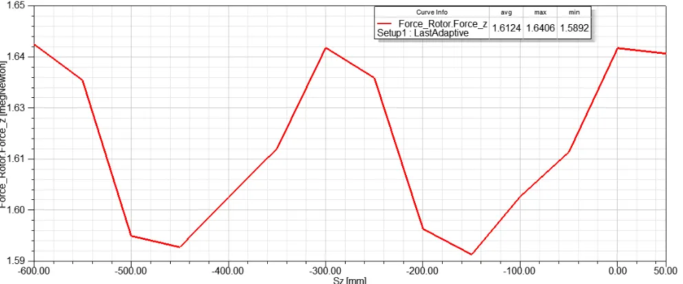
The calculation showed that for the average value of the rotor traction at least 1.6 MN, bus pairs need to be powered by the current of 685 kA. Each of the biasing system section consists of 114 kA×turns. Distribution of the rotor traction force along the acceleration channel is shown in Figure 6.
Figure 6. Rotor traction force distribution along the acceleration channel for coaxial EDRG with plane stepped PDBS cells.
Analysis of the results in Figure 6 shows that in the coaxial EDRG with plane stepped PDBS cells the value of traction deviation is 1.6%, which corresponds to the technical requirements EMALS.
2.4. Coaxial EDRG with Plane PDBS Cells Lapped Docked
Further the next embodiment of coaxial EDRG with flat PDBS cells (Figure 7) is considered and calculated.
Figure 7. Coaxial EDRG with plane PDBS cells lapped docked.
In this structure of the coaxial EDRG, the biasing coil is a
flat winding as well. The stepped overfall in the direction of the magnetic field vector here is made on the side of the coil so that two consecutive coils are joined together lapping. For the currents flowing through the rotor blades the oppositely directed current lines in the lateral edges of the biasing coil are located not close to each other, and are superimposed one on another. This design allows to compensate for the magnetic field of counter currents more fully and to reduce the value of the rotor traction deviation. The PDBS cell in this EMRG is formed by a pair of coils which are arranged on both sides of the bus pair. The gap between the biasing coils coincides with a gap formed by the power bus pair, wherein the rotor blade moves. The cells laid lapped along the acceleration channel are combined into the distributed PDBS. The coil winding height was chosen to be as maximal as possible, and the length of the bias cell was taken to be 350 mm.
Figure 8. Rotor traction force distribution along the acceleration channel for coaxial EDRG with plane PDBS cells lapped docked.
Analysis of the results in Figure 6 shows that in the coaxial EDRG with plane PDBS cells lapped docked, the value of traction deviation is 1.4%, that corresponds to the technical requirements EMALS.
2.5. Coaxial EDRG with Plane Z-shaped PDBS Cells
Here the coaxial EDRG with plane Z-shaped PDBS cells is considered (Figure 9).
Figure 9. The Coaxial EDRG with plane Z-shaped PDBS cells.
In this construction of the coaxial railgun the biasing coil is a plane winding formed into a letter Z. The PDBS cell consists of the pair of stepped coils, which are located on both sides under bus pair. The gap between the biasing coils coincides with a gap formed by the bus pair, wherein the rotor blade moves. The cells arranged with half overlap along the acceleration the channel form a distributed PDBS. As in previous designs the coil winding height was chosen to be as maximal as possible, and the length of the bias cell was taken to be 350 mm.
The calculation showed that to develop the average value of the rotor traction with the index of at least 1.6 MN, bus guides couples need to be powered by the current 715 kA. Each bias system section consists of 137 kA×turns. Distribution of the rotor of the traction force along the acceleration channel is shown in Figure 10.
Analysis of the results in Figure 10 shows that for coaxial EDRG with plane Z-shaped cell biasing system, the value of traction deviation is 0.5%, which corresponds to the technical requirements EMALS.
3. Resulting Discuss
Comparative analysis of the rotor motion simulation along the acceleration channel coaxial EDRG showed that the largest deviation of the rotor thrust technical requirements EMALS, corresponds to the third, fourth and fifth options windings PDBS cells. It is evident that a smooth acceleration is achieved by increasing the current in the circuit of the main acceleration channel power.
For further design, by the criterion of the minimum value of the deviation of the rotor thrust, coaxial electrodynamic accelerator with plane Z-shaped PDBS cells is selected.
As the rotor moves along acceleration channel, along with the increasing of its velocity, there also decreases the time of its interaction with the elements of the biasing system. Thus, in each successive PDBS cell, the generated magnetic field pulse duration should be shorter than in the previous one. It is known that the thermal effect of the current on the conductor depends, among other things, on the duration of exposure: 0 2 0
( )
t pm
R I t dt
c
T
M
=
∆
∫
, (2)where R-ohmic resistance of the conductor; t0-duration of the
current pulse; I (t)-instantaneous value of the current; cp
-molar isobaric heat capacity of the conductor material; m-mass of the conductor; M-molar mass of material; ∆ T-difference between the final and initial temperature of the conductor.
From (2) it follows that, by reducing the duration of the current pulse, ceteris paribus, it is possible to increase its amplitude, while maintaining unchanged the conductor overheating.
To perform further calculations, the following assumptions were made: form of the power current pulse in the PDBS is sinusoidal, conductor heating process is adiabatic (cooling effect is absent), conductor properties are not depended on temperature. Such simplification is quite permissible for sufficiently small pulse durations and low values of conductor overheating.
Based on the above assumptions, the process of rotor movement along the acceleration channel was simulated with the following input data:
overclocking track consists of the accelerator sections equal length Sn = 10 m;
PDBS cell length-0.35 m;
allowable overheating of the biasing coil wire-7 C0. Monitored parameters in the simulation are:
rotor velocity in the entrance of the accelerating track section, V, m/s;
time of the rotor interaction with the biasing cell (change of the rotor velocity within a section is not taken to account, interaction time with first cell of a section in constant, within this section), t, s;
number of ampere-turns in the biasing coil cell, I, kA×turns;
current in the main acceleration channel (bus pairs), IR,
kA;
deviation of traction force, d, %.
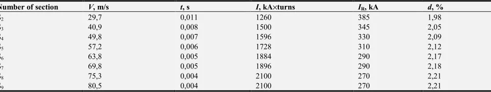
The calculation results are shown in Table 1.
Table 1. Rotor movement simulation results.
Number of section V, m/s t, s I, kА×turns IR, kА d, %
S2 29,7 0,011 1260 385 1,98
S3 40,9 0,008 1500 345 2,05
S4 49,8 0,007 1596 330 2,09
S5 57,2 0,006 1728 310 2,12
S6 63,8 0,005 1884 290 2,17
S7 69,8 0,005 1896 290 2,18
S8 75,3 0,004 2100 270 2,21
S9 80,5 0,004 2100 270 2,21
4. Conclusions
1. When designing operating accelerator complex sections
greatest current value in guiding tire pairs.
2. As the rotor velocity rises and its time of interaction with cells biasing system decreases, it becomes possible to increase the number of ampere-turns in the coils for generating the magnetic field by increasing the current density in the conductor. Wherein, the temperature of cells remains unchanged. Small time of work of separate bias cell allows its power source to work with a large duty cycle. That is, immediately after issuing the current pulse, source can enter into a power savings mode or charging. This mode allows you to use a current source to a relatively small power supply PDBS cells.
3. In each subsequent section of the booster track the rise values of thrust deflection can be seen. This is due to the fact that with increasing number of the track section, there also increases the proportion of the magnetic energy, generated by the PDBS due to increase in current density in the conductor of the coil bias. The proportion of the magnetic energy formed by the current bus pairs in guide on the contrary decreases. This increases unevenness and spatial distribution of the magnetic field generated by the PDBS. However, due to the choice of design of the bias winding system, that provides the most stable and uniform acceleration process, the parameter value of the thrust deflection does not exceed the permissible value even in the last section of the booster track. Comparative analysis of the coaxial EDRG with different variants of the biasing system coils winding has shown that the requirements EMALS for the traction force deviation satisfy the next: plane stepped PDBS cells, plane PDBS cells lapped docked, and plane Z-shaped PDBS cells.
4. The nominal value of the current in the of bus pairs with increasing numbers of track sections is reduced. In combination with a relatively low-power source of supplying of PDBS, power supply all of the accelerator complex can be achieved by the main power plant of the aircraft carrier and more powerful generators, such as the Caterpillar® [12], maritime embodiment and working in synchronization regime.
References
[1] V. I. Chumakov, O. V. Stolarchuk, Railgun System with Pulse-Dynamic Biasing of the Muzzle, Proceedings of 16th International Symposium on Electromagnetic Launch Technology (EML 2012) Beijing, China, 15-19 May, 2012, p.854, DOI: 10.1109/EML.2012.6324994.
[2] Volodymyr Chumakov, Oleksandr Stolarchuk. Hypersonic Electrodynamic Railguns with Pulse-Dynamic Biasing System. Engineering and Applied Sciences. Vol. 1, No. 3, 2016, pp. 59-65. doi: 10.11648/j.eas.20160103.13.
[3] V. I. Chumakov, O. V. Stolarchuk, Pulse processes and systems: Manual for laboratory works, Sevastopol, Naval Academy by of P. S. Nakhimov, 2012, 70 p.
[4] V. I. Chumakov, O. V. Stolarchuk, Evaluating the effectiveness of the railgun acceleration channel pulsed-dynamic biasing, Proceedings of Naval Academy by of P. S. Nakhimov, 2012, 1 (5), pp.135-144.
[5] Arsenal of XXI century, 2009, No. 1.
[6] http://army-news.ru/2014/04/rossiya-nachala-razrabotku-elektromagnitnoj-katapulty/.
[7] https://lenta.ru/news/2016/11/09/emals/.
[8] http://argumentiru.com/army/2016/04/426383.
[9] V. I. Chumakov, O. V. Stolarchuk. Simulation and Comparative Analysis of Electrodynamic Railguns for Large Masses Acceleration, to be published.
[10] http://ewh.ieee.org/soc/emcs/acstrial/newsletters/spring07/EM CSsupplement.pdf.
[11] http://www.keybridgeti.com/videotraining/manualdl/25835.P DF.