Power quality issues and minimization of
Magnetizing Inrush Current by Controlled
Switching in Three Phase Transformers
Renukadevi S. M.
Department of Electrical &Electronics Engineering. Musaliar College of Engineering& Technology, Pathanamthitta
Abstract — Three phase power Transformers are key
equipment in power systems and power plants.Security,power quality and stability of three phase transformers are both important and necessary to system operation Energization of unloaded transformer results in magnetizing inrush current very often with high amplitude ,harmonic rich currents generated when transformer cores are driven into saturation .These currents have many unfavorable effects, including operation failure of transformer differential protection, deterioration of the insulation and mechanical support structure of windings and reduced power quality of the system. The inrush currents are always unbalanced among three phases. The amplitude of the magnetizing current depends mainly on two factors; the residual flux in the magnetic core and the transient flux produced by the integral of the sinusoidal supply voltage. To satisfy the principle of the flux steadiness, it is necessary to build an equalizing flux with the same magnitude, but opposite polarity to the prospective flux. Inrush currents from transformer and reactor energization have always been concern in power industry. So it is needed to find simpler and low cost scheme to limit these currents. Independent power producers are especially interested in such techniques. Different methods are used for minimizing the transient current. In this Simultaneous closing of circuit breaker and sequential closing of circuit breakers are used for reduce this large current Electric utilities and end users of electrical power are becoming increasingly concerned about the quality of electric power. A neutral resistor could provide some damping to the currents. The idea is further improved by introducing controlled energization of each phase of the transformer. The performance and characteristics of the proposed scheme is investigated using MAT LAB simulations.
Index Terms: Inrush current, power quality,
controlled switching
I.INTRODUCTION
Electric power transformers play an important role in the stable operation of power systems. A power transformer functions as a node to connect two different voltage levels. Therefore, the continuity of transformer operation is of vital importance in maintaining the reliability of power supply. The major concern in power transformer protection is to avoid the false tripping of the protective relays due to the misidentifying the magnetizing inrush current.
In this paper we propose transformer-based solutions to several power quality problems. Elsewhere we have shown how to solve the acoustical noise emission problems. In this paper we introduce toroidal transformers with reduced inrush currents, transformers with reduced electromagnetic emissions, and other transformers useful to reduce the transfer of harmonics. With the low-inrush transformers we are able of eliminating (or reducing) voltage sags and nuisance service interruptions caused by false operation of breakers and fuses. The low-stray emissions transformers are used for reducing the electromagnetic interference (EMI) caused by stray fields emitted from the transformer. Electromagnetic noise reduction transformers (NRT) are used reduce the harmonic pollution problem.
limiting circuits. Therefore, we increase the reliability of the overall system while simultaneously reducing cost. We have also reduced the electromagnetic field emissions even below the already reduced fields emitted by standard toroidal transformers. In addition, we have invented a transformer with a narrow frequency bandwidth to limit the transfer of harmonics from primary to secondary or vice versa
Inrush currents are instantaneous currents flowing in the transformer primary circuit when it is energized. Uncontrolled energization of large power transformers may result in large dynamic flux and saturation in one or more cores of the transformer. The saturation result in high amplitude magnetizing inrush current that are rich in harmonics and have DC component. They are normally of short duration, usually of the order of milliseconds. Sometimes it may reach up to 10-20 times the rated current. In the case of three phase transformers, these currents are highly unbalanced. They are found to be interfering with the normal operation of the power systems. Some of the problems caused by inrush currents are operation failure of transformer differential protection, deterioration of the insulation and mechanical support structure of windings and reduced power quality of the system. Without controlled switching the energization may occur at any time on the voltage wave producing high inrush current peak when the transformer core is driven into saturation.
Transformer inrush current due to flux saturation in the core is a transient phenomenon. Normally transformers are designed to operate below the knee of the saturation curve. But when switched on no load, flux builds up to a high value; thereby falls in the saturation region and this causes the current to increase. It has been found that in cores having certain amount of remanant flux, the inrush current is many times higher than that in cores having no remanance. These currents can cause false operation of protective relays and fuses.. Closing resistors have been used to reduce the magnitude of inrush currents. Controlled closing, or controlling the point on the power frequency voltage wave where energization occurs, has also been employed to reduce these inrush transients and thus improving power quality
II.INRUSHCURRENT
Inrush current or input surge current refers to the maximum, instantaneous input current drawn by an electrical device when first turned on. When transformer energizes a transient current much larger than the rated current flow several cycle. This is caused
because the transformer will always have some residual flux density and when the transformer in re energized the incoming flux will add to the already existing flux which will cause the transformer to move into saturation. This transient current is called inrush current.
The phenomenon of transient transformer inrush currents [11] was published by Fleming in 1892. Anyhow, up to 1988 the only method to reduce inrush currents was the installation of pre-insertion resistors. Transient transformer inrush currents can exceed the nominal current and may achieve the rated value of the short-circuit current of the power transformer. The amplitude is decaying very slowly and reaches its steady magnetizing current after some seconds. Decay rate of inrush current is determined by the ratio of resistance to inductance of primary winding. The current wave form is completely offset in the first few cycles.
Inrush Current is in the form of over-current that occurs during energization of a transformer and is a large transient current which is caused by part cycle saturation of the magnetic core of the transformer. For power transformers, the magnitude of the first peak of inrush current is initially several times the rated load current but slowly decreases by the effect of oscillation damping due to winding and magnetizing resistances of the transformer as well as the impedance of the system it is connected to until it finally reaches the normal exciting current value. This process typically takes several minutes. As a result, inrush current could be mistaken for a short circuit current and the transformer is erroneously taken out of service by the over - current or the differential relays. Therefore, it is important to have an accurate calculated value of the magnitude and other parameters of inrush current in order to design the relaying to properly differentiate between inrush and short circuit incidents.
Uncontrolled energization of large power transformers may result in large dynamic flux and saturation in one or more cores of the transformer. The saturation results in high amplitude magnetizing inrush current that are rich in harmonics and have a high direct current component. The amplitude of the magnetizing current depends mainly on two factors: the residual flux in the magnetic core and the transient flux produced by the integral of the sinusoidal supply voltage.
opposite polarity to the prospective flux. This way the transient flux starts from the residual flux and reaches its highest amplitude a half period later. At that point the flux saturates the core and a high amplitude inrush current appears because the inductance of the magnetic core is very small in that region.
Fig.1 Saturation characteristic
A typical inrush current wave form is as shown in the Fig.1 which describes the flux-current characteristic and determines the magnitude of the magnetizing and inrush current for a) symmetrical and b) unsymmetrical core fluxes. . The normal flux leads the transformer to operate in the linear region. Where the magnetizing current will be in the rated value, but the flux asymmetry leads the transformer to operate in the saturation region and a high magnitude current is produced during energization
III. FACTORS DETERMINING INRUSH CURRENT
A. Size of transformer:
Peak values of inrush current are higher for smaller transformers while for larger substation-type transformers the inrush peak will be lower, but the inrush duration longer. The time constant for the decaying current is in the range of 0.1 of a second for small transformers and in the range of 1second for larger units [9].
B. Impedance of system from which transformers in
energized
The inrush current is higher when the transformer is energized from a powerful system. The total resistance seen from equivalent source to the magnetizing branch contributed to the damping of current. Thus transformers are located closer to the generating plants display inrush currents lasting
much longer than transformers installed electrically away from generators.
C. Magnetic properties of core material
The magnetizing inrush is more severe when the saturation flux density of the core is low. Designers work with flux densities of 1.5 to 1.75 Tesla.
D. Remanence in the core
When a transformer is de-energized, the magnetizing voltage is taken away, the magnetizing current hysterics loop of the core. The results in certain remnant flux left in the core when afterwards, the transformer is re-energized by an alternating sinusoidal voltage, the flux becomes also sinusoidal but biased by the remanence. The residual flux may be as high as 80 -90% of the rated flux. It may shift the flux current trajectories far above the knee point of the characteristic resulting in both large peak values and heavy distortions of the magnetizing current
.
E. Moment when the transformer is switched in
(The voltage phase angle)
The highest value of magnetizing inrush current occurs when the transformer is switched at the transition of the winding voltage and when in addition the new forced flux assumes the same direction as the flux left in the core.
When a transformer is switched on to a line, at times circuit breaker trips or a fuse blows. This happens even if the transformer is on no load, i.e. its secondary is open circuited. This is due to the heavy current drawn by the transformer. Inrush current is described as the magnitude of instantaneous input current drawn by the line frequency power transformer at the time when the core is energized. Random power transformer energization can create large flux asymmetries. That is if the transformer is switched on when the ac voltage wave form is going through its zero value then the current drawn by the transformer will be very high. That is if the transformer is switched on at the instant of zero value of the voltage wave form, the total transformer flux will become two times the maximum flux.
IV. PROBLEMS CAUSED BY INRUSH CURRENT
Inrush currents have a significant impact on the supply system and neighboring facilities.
sensitive electronics and interrupt the manufacturing process.
The wave form of an inrush current is far from sinusoidal and it containing a lot of high frequency components. Such harmonics could interact with the filters installed in the system.
The DC component of the inrush current can lead to oscillatory torque in motors resulting to increase motor vibration and aging.
A. Power quality problem due to magnetizing inrush
From power quality point of view, the magnetizing inrush current can be considered as a distorted wave with two kinds of disturbances.
They are unbalance and harmonics.
a) Unbalance
Asymmetrical loads produce unbalanced currents. In the same way, the magnetizing inrush current produces current unbalance during magnetization. This condition can be used in parallel with the second harmonic in order to know what will happen during the energization of the transformer.
b) Harmonics
The current demanded by the transformer during the magnetization contains all orders of harmonics. However, only the second and third harmonics are relevant. The dc component can also be significant during the first few cycles depending on the residual flux. The most significant harmonics are the following.
DC or offset component.
Second harmonic
Third harmonic
Higher harmonics.
Power quality can be described in terms of voltage as any deviation of the magnitude, frequency, or purity from the ideal sinusoidal voltage waveforms. Many distortions occur in the system so the quality of power varies. Typically, the deviations are classified as transients (impulsive or oscillatory), interruption, voltage dip (sag) or under voltage, voltage swell or overvoltage, voltage unbalance, waveform
distortion (i.e. DC offset, harmonics, inter harmonics, notching, noise), voltage fluctuations (flicker), and power frequency variations. In the context of controlled switching, it is the deviations and consequences associated with voltage sag, transients, and interruptions that are of interest. Energization of shunt capacitor banks and power transformers has a direct influence on power quality, while that of transmission
line reclosing is directly or indirectly dependent on the nature of the power system
V.PROPOSEDSCHEME
Inrush currents from transformer and reactor energization have always been a concern in power industry. Pre-insertion of series resistors and synchronous closing of circuit breakers are examples of available mitigation techniques. These currents are undesirable for some protective system, especially in high -tech industries. So, few techniques of mitigating these currents have been proposed to limit the inrush current. The power quality consequences of inrush currents can be quite detrimental. Examples are motor tripping, relay misoperation and so on. There is still a need to find simpler and low cost schemes to limit these currents. Independent power producers are especially interested in such techniques.
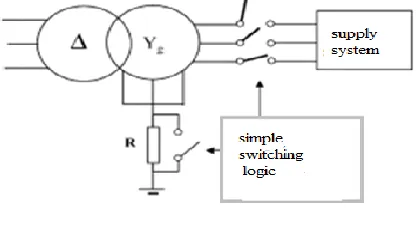
Fig 2. Model
Fig 2 shows the proposed model for the work. The system consists of source of the supply system, line parameters, circuit breakers, power transformer and a grounding resistor. By using this scheme [8], [21] the simulation has been done for the following methods
1. Simultaneous closing
2. Simultaneous closing with neutral resistance 3. Sequential Closing
4. Sequential Closing with neutral resistance
The phase energization method is tested by carrying out simulations. The various circuits were simulated using MATLAB software. The rating of the transformer used for simulation is 31.5MVA, 110/ 11 KV, Y -∆. To assess the inrush current, the following test configuration were generated and studied using simulation results;
1. Circuit breaker switching conditions changes 2. Topology with/without neutral resistance
will also contain the inrush current. One may, therefore, speculate that if a resistor is inserted into the transformer neutral, it may reduce the magnitude of the inrush current in a way similar to that of the series-inserted resistor. Neutral could provide some damping to the currents. This consideration formed the basic idea of the proposed scheme.
The idea is further improved by introducing controlled energization of each phase of the transformer. In order to achieve inrush currents free energization of large power transformers, the operating times of the circuit breakers poles must be controlled individually and performing contacts closing in a proper sequence. That method is used in the controlled switching. All simulations were performed without a load on the secondary side [12].
Effect of varying neutral resistance on irush current reduction was found out by putting different values of neutral resistance in the simulation circuit..
1 Sequential closing with Rn ( Time delay of CB-
0.06,0.14.0.2)
For each phase energisation graph is plotted between inrush current and neutral resistance as shown in Fig 3.
Fig .3 Variation of inrush current with neutral resistance(1)
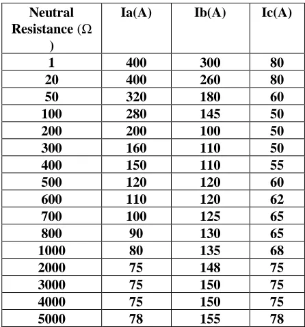
For finding the optimal value of resistance another switching time is considered for the same resistance.Table1shows the simulation results of that switching time of CB.
2 Sequential closing with Rn (Time delay of CB
-0.06,0.12,0.18)
Varying the switching time of CB with constant delay observe the value of inrush current in each phase.Table 1 shows the simulation results.
Neutral Resistance (Ω
)
Ia(A) Ib(A) Ic(A)
1 400 300 80
20 400 260 80
50 320 180 60
100 280 145 50
200 200 100 50
300 160 110 50
400 150 110 55
500 120 120 60
600 110 120 62
700 100 125 65
800 90 130 65
1000 80 135 68
2000 75 148 75
3000 75 150 75
4000 75 150 75
5000 78 155 78
Table 1 Optimal value of neutral resistance(2)
In this energisation observe the variation of current in each phase and a graph is plotted between inrush
current and neutral resistance as shown in Fig 4
Fig 4 Variation of inrush current with neutral resistance(2)
be concluded that there is an optimal value of resistance at which maximum inrush current reduction is obtained. The second phase energisation is the one most difficult to analyse.The important conclusion at present is that the first phase energisation should be the focus point for developing the optimal Rn.This optimal value of Rn is the resistance corresponding to the interaction point of the third phase energisation curve with the higher one of the first and second energisation curves.Hence the approximate value of optimal resistor obtained from graph is 1000Ω.
VI. CONTROLLED SWITCHING
The uncontrolled energizing of power transformers can result in dynamic phenomena in magnetic cores, causing them does operate with a high saturation level in transient conditions.
In fact, when the transformer is energized at the zero crossing of the voltage wave, the transient core flux produced by the supply voltage and the magnetization current, may achieve their maximum values. For this to happen, it is necessary that at the moment the switches close, the instantaneous voltages produce fluxes equal to those already present in the magnetic columns of the transformer core . By using this approach, no transient magnetizing inrush would occur and the final steady state condition of the transformers would be achieved.
As the slopes of the characteristics are significantly different at this point, the inductances of the two windings are also significantly different. Therefore, the voltage on the windings is not divided evenly, i.e. the winding with the largest inductance will have the highest voltage. This higher voltage will create a higher flux level, increasing the B-phase flux towards the magnitude of the C-phase flux. The result is that the flux in B and C phases rapidly equalizes and eliminates the effect of their residual flux. This phenomenon is referred to as ―core flux equalization.‖
Fig.5.Flux current core characteristics
In most three-phase transformers, the flux in the main core leg sum to zero. This is true for transformers with a three legged core or a delta winding. It is not the case for transformers without a delta-connected winding
that are single phase or have five-legged or shell-form cores. If one phase of a transformer which is configured such that fluxes sum to zero is energized such that its core leg does not go into saturation, the flux in that phase is equal to its prospective flux at every instant. Since the prospective fluxes and the core fluxes must sum to zero, the induced dynamic core fluxes must equal their prospective fluxes two times per cycle. Where A-phase with zero residual flux is closed at point ―A‖ and immediately induces dynamic fluxes in phase B and C
Depending upon the polarities of the residual flux in the two legs, the dynamic core flux and prospective fluxes will be equal either at the point marked ―B‖ or ―C‖ in Fig-6. These points offer the opportunity to energize the other two phases without saturation of the core. This closing strategy is called ―rapid closing.‖ The point marked ―B‖ obviously is more tolerant to closing timing error than point ―C‖, since the slopes of the prospective and dynamic fluxes are nearly equal for a period of approximately a millisecond, which is not the case at point ―C‖. Another interesting closing opportunity can also be observed in the above Fig 6. At point ―A‖, where the first phase is closed, the dynamic and prospective fluxes of the other two phases are nearly equal and therefore optimal for this residual flux pattern. If the residual fluxes were slightly higher on these two phases, point ―A‖ would be optimal for a simultaneous closing of all three phases. This offers some unique opportunities for lower voltage systems, where independent-pole-control circuit breakers are uncommon. This is called the ―simultaneous‖ closing strategy.
Fig.6 Prospective and dynamic core flux with residual flux
Rapid closing strategy
This strategy closes one phase first and the remaining two phases within a quarter cycles. It requires of knowledge of residual flux in all the three phases, independent pole breaker control and a model of the transformers transient performance.
Delayed closing strategy
This strategy closes one phase first and the remaining two phases after the 2-3 cycles. It requires knowledge of residual flux in one phase only, independent pole breaker control, but does not require any transformer parameter data.
Simultaneous closing strategy
This strategy closes all three phases together at an optimum point for the residual flux pattern [6]. It does not require independent pole breaker control, but requires the knowledge of the residual flux in all the three phases and that the residual flux magnitudes in two phases are high and follow the most traditional residual flux pattern.
Switching of 3 –phase CB by various control strategies are done by using the simulink model .
a) Rapid closing
0 0.05 0.1 0.15 0.2 0.25 0.3 0.35 0.4 0.45 0.5
-200 0 200 400 In ru s h c u rr e n t( A ) Ia
0 0.05 0.1 0.15 0.2 0.25 0.3 0.35 0.4 0.45 0.5
-200 -100 0 100 Ib In ru s h c u rr e n t( A )
0 0.05 0.1 0.15 0.2 0.25 0.3 0.35 0.4 0.45 0.5
-400 -200 0 200 Ic Time(s) In ru s h c u rr e n t( A )
Fig.7 Simulated output of Rapid closing
In Rapid closing ,energise the first phase at 3 cycle and the other phases B&C closed after quarter cycle.The simulation results are shown in fig 7
b) Delayed closing
0 0.05 0.1 0.15 0.2 0.25 0.3 0.35 0.4 0.45 0.5 -500 0 500 In ru s h c u rr e n ts (A ) Ia
0 0.05 0.1 0.15 0.2 0.25 0.3 0.35 0.4 0.45 0.5 -400
-200 0 200
Ib
0 2000 4000 6000 8000 10000 12000 14000 16000 -100
0
100 Ic
Time(s)
Fig..8 Simulated output of Delayed closing
In delayed closing ,the second and third poles of the breaker are operated with significant delay.The simulation results are shown in Fig.8
c) Simultaneous closing
0 0.05 0.1 0.15 0.2 0.25 0.3 0.35 0.4 0.45 0.5
-200 0 200 400
Ia
0 0.05 0.1 0.15 0.2 0.25 0.3 0.35 0.4 0.45 0.5
-500 0 500 In ru s h c u rr e n t( A ) Ib
0 0.05 0.1 0.15 0.2 0.25 0.3 0.35 0.4 0.45 0.5
-200 0 200
Ic
Time(s)
Fig.9 Simulated output of simultaneous closin In simultaneous closing all phases are closed at the same time .The simulation results are shown in Fig.9.
Consequences on Power quality
Applicati on Consequences on Power Quality without Controlled Switching With Controlled Switching Closing on shunt capacitor or filter banks
Severe voltage dip
and recovery
transient at station bus; transferred surges to other parts
of the system
including customer owned stations
Virtually
eliminates the voltage dip and subsequent transients and surges. Closing on unloaded power transforme rs
Severe voltage dip at station bus can occur; in addition, inrush current may cause protection misoperation.
Virtually
eliminates the
voltage dip,
inrush current limited to almost steady state value
Transmiss ion line autoreclosi ng
Switching
overvoltages and possible
unsuccessful reclosing caused by breakdown of line insulation.
VII. CONCLUSION
Simultaneous closing of all three phase breakers did not produce sufficient reductions on the inrush currents.We reasoned,that if one closes each phase of the breaker in sequence with some delays between them,a neutral resistance could behave as a series resistor and improve the results.This simple improvement has proven to be very effective.So sequential energisation of three phase equipment with neutral resistor is effective.The phenomena of core flux
reduction can greatly simplify closing
strategies,allowing the delayed strategy to be very effective.The delayed strategy can also provide a reduction of inrush transients when switching transformer with more than three core legs .However,complete elimination of inrushcurrent is not possible with these configuration.. Further investigation is to determine how to achieve this is a practical and ecconomical manner.
REFERENCES
[1] Allen Greenwood, ―Electrical Transients in Power Systems‖
Second edition,John Willey&Sons,Inc.NewYork,ISBN 978-0-471-62058-7
[2] C. Sankaran, ―Power Quality‖, Taylor&Fransis Group, The
Electric Power Engineering Series, ISBN-9780849310409, 216pp.
[3] Bharat Heavy Electricals Limited, ―Transformers‖, Second
edition, Tata McGraw-Hill,ISBN 0-07-048315-9,2007
[4] William.M.Flanagan, ―Hand book of Transformer Design
&Applications‖ Second Edition ,MC Graw-Hill
J.H.Brunke,K.J.Frohlich. ―Elimination of transformer inrush
currents by controlled switching-Part I :Theoretical
considerations‖ IEEE Trans. Power Del., vol.16, no.2, pp. 276-280, Apr.2001.
[5] J.H.Brunke ,K.J.Frohlich, ―Elimination of transformer inrush
currents by controlled switching - Part II: Application and performance considerations‖ IEEE Trans.Power Del., vol.16, no.2, pp. 281-285, Apr.2001.
[6] Y.Cui, S.G. Abdulsalam, Y ―A sequential phase engergization
technique for transformer inrush current reduction –part I: simulation and experimental result‖,IEEE Transactions on power Delivery, Vol.20,No-2 April 2005,pp.943-949.
[7] Sami G. Abdulsalam, Wilsum XU, ―Analytical study of
transformer Inrush current Transients and its applications‖ IPST05 in Montreal Canada on June19-23,2005 paper No.IPST05-140
[8] Paul C. Y. Ling, A. K. Al-Khalifah, ―Investigation of Magnetizing
Inrush Current in a Single-Phase Transformer‖, IEEE Transaction on Magnetics, vol. 24, No. 6, Nov. 1988, pp. 3217-3222. [9] W. Xu, S.G. Abdulsalam, Y. Cui, S. and X. Liu, ―A Sequential
Phase Energization Method for transformer inrush current reduction, Part II: Theoretical Analysis and Design Guide", IEEE Trans. Power Delivery, vol. 20, pp. 950-957, April 2005.
[10] Fleming J.A:‖Experimental Researches on Alternate Current
Transformers‖ Journel of the IEEE,Vol.21.sec V111(1892) pp.677-685.
[11] Chen Zhe, Wen Yuanfang, Lu Guojun ―Improved Modeling and
Calculation on electctro magnetic transient of power
Transformer.’’ IPEMC 2006
[12] Andreas Ebner ,ETH Zurich: ―Transient Transformer inrush
currents due to Closing Time-and Residual Flux
Measurements-Deviations if Controlled Switching is used.‖-A real case
study,cigre session 2002,N0.13-201.
[13] Laszlo Prikler, Gyorgy Banfai, Gabor Ban and Peter Becker,
―Reducing the Magnetizing Inrush current by means of Controlled Energization and de-Energization of Large Power Transformers,‖ International Conference on Power System Transients, IPST 2003.
[14] Juei-Lung- Shyru, Chung shan, ―A Novel control strategy to
reduce transformer inrush current by series compensator‖. IEEE proceedings Electric Power application Vol.151.pp 289-295, 2005.
[15] Li Dongxia, Wang Zanji, Liu Xiucheng ―Modeling and simulation
of magnetizing inrush current of large power transformers‖. Proceedings of POWERCON 2000, 4-7 December, 2000, Perth, Australia, pp795-800.
[16] K.P.Basu.Ali AsgharR. ―Reduction of magnetising inrush current
in a delta connected transformer‖ .Conference on power electronics,Drives and Energy systems for Industrial Growth (PEDES2006), pp 1-4.
[17] Yacamini and H.Bronzeado, ―Transformer inrush calculation
using a coupled electromagnetic model‖, IEE
Proc.Sci.Meas.Technol., V.141, No. 06, November/1994.
[18] A.C.Carvalho, J.H.Sawada, D.F.Peelo, ―Experiences with
improving Power Quality by Controlled Switching.‖CIGRE W G A 3.07.Seminar and workshop on controlled switching FL, USA, 7 May 2003.
[19] Liana Cipcigan,WilsunXu,Venkata Dinavahi, ―A New Technique
to Mitigate Inrush Current Caused by Transformer Energization’’ in Proc. IEEE 2002 PES Summer meeting ,Chicago ,USA, Jul. 2002.
[20] A.L.J.Jansen, J.H.Brunke, W.Lanz ―Studies on the reliability of single pressure SF6-gas High voltage circuit Breakers.‖IEEE
Transactions on power delivery vol.11. No-1 January1996.