DOI: 10.1051/epjconf/20135911004 C
Owned by the authors, published by EDP Sciences, 2013
Principles and issues related to SBS-PCM based
self-navigation of lasers on injected pellets
Milan Kalal
1,a, Hong Jin Kong
2and Ondrej Slezak
11Faculty of Nuclear Sciences and Physical Engineering, Czech Technical University in
Prague, Brehova 7, 115 19 Prague 1, Czech Republic
2Department of Physics, Korea Advanced Institute of Science and Technology, 373-1
Gusong-dong, Yusong-gu, Daejeon, 305-701 Republic of Korea
Abstract. Current status of recently proposed novel approach to inertial fusion energy technology, where phase conjugating mirrors generated by stimulated Brillouin scattering are employed to take care of automatic self-navigation of every individual laser beam on injected pellets, has been reviewed. This novel technology is of a particular importance to the direct drive schemes of pellets irradiation as assumed, e.g., in HiPER project. If successful also in its full scale realization, such an aiming scheme would greatly reduce the technical challenges of adjusting large and heavy optical elements on each shot in a system with a repetition rate of at least several Hertz. In the gradual step-by-step tuning of this technology, in this paper a close attention has been paid to the unconverted basic harmonic issue with a special Faraday isolator design proposed. However, a practical realization of this component in its simplest form might be somewhat difficult to achieve due to a suitable optical material shortage. Hence, a more elaborate scheme of this isolator which would make its realization much more realistic even for optical materials currently available has been examined and will be presented.
1. INTRODUCTION
One of the very difficult challenges to deal with in the direct drive IFE integrated approach is connected with the need of simultaneous irradiation of thermonuclear pellets by many dozens (or even hundreds) of powerful laser beams inside the reactor chamber. Sophisticated tracking of injected pellets’ trajectories is necessary for prediction of the place most suitable for interaction with the driver beams in order to achieve necessary irradiation symmetry and subsequent fuel compression.
For the direct drive scheme the following set of parameters is being currently considered: pellets
∼4 mm in diameter should be delivered into the virtual sphere of∼5 mm in diameter located around the center of the reactor chamber∼10 m in diameter. Combined precision of tracking and aiming should be∼20m. Unfortunately, navigation technologies developed so far (despite their gradual progress) are still well outside of the required margin even in the case of fully evacuated reactor chambers - as some time consuming adjustment of heavy final optics for every shot and every laser beam is always necessary. This last fact is also partially responsible for the very tight margin (∼500m) on the pellets successful delivery into the above mentioned virtual sphere.
In reality there are some additional serious obstacles further complicating this direct drive IFE scheme – even putting its practical feasibility in doubts. Among the most serious ones is an insufficient predictability of the injected pellets’ trajectories resulting from their expected interaction with remnants of previous fusion explosions due to the considered 5–10 Hz repetition rate. This might be one of
ae-mail:[email protected]
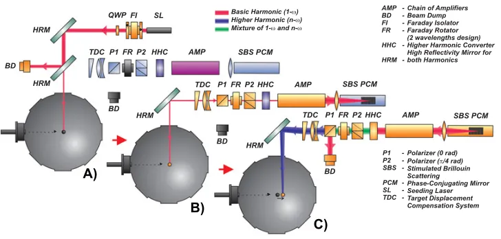
Figure 1. Three stages of the self–navigation system operation.
the reasons why the indirect drive scheme has been considered a more serious IFE candidate as the corresponding hohlraum targets are by three orders of magnitude heavier compared to their direct drive counterparts thus allowing for much more reliable prediction of their trajectories.
In order to deal with these direct drive IFE scheme laser navigation difficulties a novel approach was recently proposed employing SBS PCM technique [1,2]. In the very first public presentation of this approach [3] it was predicted that a fully automatic self-navigation of every individual laser beam on injected pellets with no need for the final optics adjustment could be achieved. This idea has been undergoing gradual improvement in its theoretical design [4–6] and subsequently it started to be tested also experimentally - proving the principle [7].
2. LASER DRIVER CURRENT DESIGN STATUS
Since its first introduction [4] the laser driver design has been gradually modified. Its current design is schematically illustrated in Fig.1using three basic stages of the laser driver functioning.
A) At the right moment (determined by careful tracking) when the injected pellet is approaching its best interaction position, a low energy seeding laser pulse (glint - red line) is sent to illuminate the pellet; B) Reflected seeding laser pulse is collected by the focusing optics and amplified on its way to the SBS
PCM cell;
C) Amplified pulse is reflected by the SBS PCM cell, amplified once again, major part of its energy is subsequently converted to higher harmonic (blue line) and automatically aimed at the moving pellet by the target displacement compensation system (TDC) for its final high power irradiation. The unconverted part is removed by a special double-wavelength Faraday isolator.
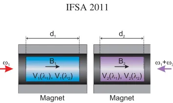
Figure 2. Double-wavelength FR design (basic scheme):d- active medium langth,B- magnetic field magnitude,
V - Verdet constant.
the position in which they will be irradiated would always be the same (provided, that the injection speed will not vary substantially from shot to shot).
3. FARADAY ROTATOR
In this latest scheme there is one new optical system - special Faraday isolator - included in every laser channel. It consists of the wavelength-sensitive custom-design Faraday rotator (FR) placed between two polarizers (P1 and P2). The main role of this optical system is to prevent the returning non-converted basic harmonic from entering the reactor chamber. The very same basic harmonic which must be allowed on its first pass towards SBS PCM reflection to propagate without any substantial attenuation. The basics of this design were already published [8].
In this paper we would like to further improve this device by a tandem design (using two different materials and two different magnetic fields) which was chosen as the most efficient practical solution. It does not feature so strict demands on the material properties, because its proper functionality can be tuned by the active materials length ratiod1/d2 as well as by the magnetic fields ratio B1/B2, or by combination of both of these parameters. The basic scheme of this upgraded device is depicted in Fig.2. The required angle of rotation(1) of the plane of polarization for the basic harmonic during each pass can be written in the following generalized form
(1)=B1V1(1)d1+B2V2(1)d2=
4 +m1, (1)
whereVi(j) is the Verdet constant of thei-th medium for the wavelengthj,Biis the value of thei-th magnetic field applied to the cylinder of the lengthdi, andmi is the whole (non-negative) number,i andj stands for the FR index and so it acquires the value of either 1 or 2. Under these conditions the Faraday isolator will properly take care of the basic harmonic.
What rotation angels(2) are required for the higher harmonic? This harmonic should be allowed a free passage through the Faraday isolator on its way to the reactor chamber. Thus, the generalized formula should assume the form
(2)=B1V1(2)d1+B2V2(2)d2 = 3
4 +m2. (2)
Provided that
V1(1)V2(2)=V1(2)V2(1) (3) is valid (this condition excludes the single material design), the general solution of the set of equations (1) and (2) may be found in the form
d1=
B1D
V2(2)
1 4 +m1
−V2(1)
3 4 +m2
The solution (4) has the physical meaning only in cased1,d2>0. Nevertheless, this condition can be fulfilled for any combination of materials by tuning the ratioB1/B2.
Due to the suppression of the negative influence of material absorption and nonlinear effects (which should be the biggest challenge from the point of view of material selection) it is convenient to design the rotator as short as possible (L=d1+d2is minimal), where
L= D B1B2
(B2V2(2)−B1V1(2))
1 4 +m1
+(B1V1(1)−B2V2(1))
3 4+m2
. The shortest possible configuration (for arbitrary materials) is obtained form1=m2=0 andt|B1| =
|B2| ≡Bas high as possible. The proper direction of the magnetic fieldsB1,B2according to the value ofV1
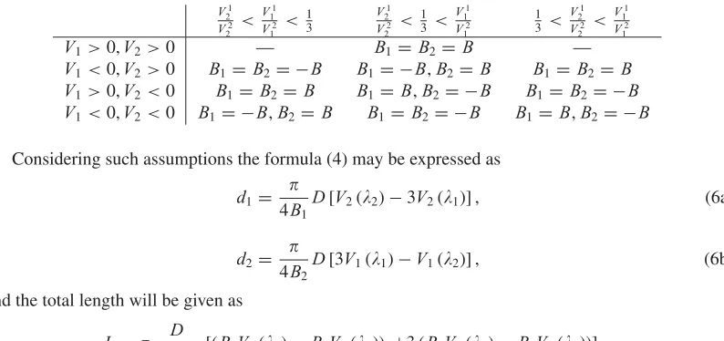
2/V22andV11/V12ratios is summarized in Table1. Table 1. Magnetic field direction.
V1 2 V2 2 < V1 1 V2 1 < 1 3 V1 2 V2 2 < 1 3 < V1 1 V2 1 1 3 < V1 2 V2 2 < V1 1 V2 1
V1>0,V2 >0 — B1=B2=B —
V1<0,V2 >0 B1=B2= −B B1 = −B,B2=B B1=B2 =B
V1>0,V2 <0 B1 =B2=B B1 =B,B2= −B B1=B2= −B
V1<0,V2 <0 B1= −B,B2=B B1=B2= −B B1=B,B2= −B
Considering such assumptions the formula (4) may be expressed as
d1= 4B1D
[V2(2)−3V2(1)] , (6a)
d2=
4B2D
[3V1(1)−V1(2)] , (6b)
and the total length will be given as
L= D
4B1B2
[(B2V2(2)−B1V1(2)) +3 (B1V1(1)−B2V2(1))] .
Taking advantage from this consideration it is possible to calculate the example design of this two-wavelength design of FR. Let us design it for Nd:YAG laser for its basic and the second harmonic frequency. This leads to the wavelengths 1=1064 nm and 2=532 nm. Using the crystals of
T b3Ga5O12(TGG) andKT b3F10as active materials (the appropriate Verdet constants are summarized in Table2, the Verdet constant values for the second harmonic were obtained by the interpolation from the measured values for other wavelengths).
Table 2. Verdet constants of two particular crystals.
Crystal [nm] Vrad.m−1.T−1 Ref.
T b3Ga5O12
1064 −35
[9,10]
532 −227
KT b3F10 1064 −33.2
[11]
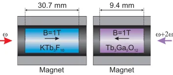
Figure 3. Two-wavelength FR example design.
Substituting the material parameters into equations (6) and using the permanent magnet characterized by the magnetic field magnitude of|B1| = |B2| =1 T one will get the solution
d1=30.7 mm, d2=9.4 mm. (7)
The resulting FR design is then depicted in Fig.3.
4. CONCLUSIONS
In front of gradually emerging obstacles (e.g., the uncertainty connected with the cross-talk between individual laser drivers), confidence related to the indirect drive schemes as the preferred IFE approach keeps decreasing. Thus providing more room for the direct drive IFE scenarios, where the suitable aiming scheme belongs to the crucial issues. Having so far no final solution to this challenge, any potential avenue which comes into consideration should be carefully explored before being rejected. Into this category should belong also the self-navigation concept advocated and studied by us.
There are certainly many particularities to study in this context. Some of them can be mentioned for inspiration: (a) Analysis of the wavefront quality for the collected seeding beams after their reflection from the pellet; (b) Detailed analysis of the illumination schemes needed to obtain as homogenous seed reflection as possible for the pellet in the arbitrary position around the chamber center (i.e., consideration of the problems caused by the seeding beam entering the system under some small angle due to the pellet offset from the ideal position during its illumination/reflection); (c) Evaluation of the wavefront cleaning effect of the PCM for a longer AMP chain (this will effectively limit the maximum energy one such channel can work with); (d) Thermal stress induced depolarization compensation by the FR between the AMP and SBS PCM; (e) Possible merging of the beam combination technique with the self-navigation one. Some of the above mentioned issues are already under consideration or even being actively studied. Also, the main topic of this paper, the unconverted harmonic removal by a special Faraday isolator design is going to be tested soon by us.
Let us conclude by the statement that the self-navigation technology should be worth of being paid attention to by some properly equipped major laboratory. As it should be relatively easy to extend our original verification experiments successfully performed on a smaller scale to much more interesting levels. It is our real pleasure to mention that the HiPER managers are in touch with us on this issue. And there is a good chance that these kind of experiments shall be performed soon in Korea.
References
[1] B.Y. Zel’dovich et al., Sov. Phys. JETP 15, 109 (1972)
[2] Phase Conjugate Laser Optics, ed. by A. Brignon, J.-P. Huignard, (Wiley-Interscience, New York 2003)
[10] D.J. Dentz, R.C. Puttbach, and R.F. Belt, AIP Conf. Proc. 18, 954 (1974)