IJEDR1702214
International Journal of Engineering Development and Research (www.ijedr.org)1369
“Effect of Confining Reinforcement on Behavior of
Rectangular and Square column”
1
Swapnil Kharade, UG Student, Dept of Civil Engineering, DYPSOET Pune,
2
Rushikesh Kate, UG Student, Dept of Civil Engineering, DYPSOET Pune,
3
Riya Bhole, UG Student, Dept of Civil Engineering, DYPSOET Pune,
4
Prasad Jadhav, UG Student, Dept of Civil Engineering, DYPSOET Pune,
5
Manoj Lamkhade, UG Student, Dept of Civil Engineering, DYPSOET Pune,
Abstract -It is found that the design of structure is uneconomical in the elastic range when subjected the earthquake induced inertial forces, so it is required to design the structures so that the energy can be dissipated by post elastic deformation of the members which requires certain elements to be designed for ductility as well as strength. To avoid the formation of the plastic hinges in the column most of the codes prefer “strong column and weak beam” theory hence the reinforcement in the column should be carefully designed. The transverse reinforcement plays an important role in the ductility of the column. The preparedness for the formation of the plastic hinges in column, it requires confinement of concrete by transverse reinforcement. This Project deals with the effectiveness of the Confining reinforcement, its quantity , working out the optimum combination of the confinement reinforcement and also the load carrying capacity of the rectangular column. The study of rectangular column is significant as it is used mostly in the practical building construction and also the confinement reinforcement design for the columns with square and circular cross section has proven more effective as compared to the rectangular column.
I. INTRODUCTION :
It is uneconomical to design the structure to respond in the elastic range to the greatest likely earthquake induced inertial forces because the maximum response acceleration may be several times the max ground acceleration, depending on the stiffness of the structure and the magnitude of damping. This suggest the necessity to design structures so that the energy can be dissipated by post elastic deformation of members, which requires certain elements to be designed for ductility as well as strength. It is well known that the ductile behaviour of concrete sections can be attained by carefully detailed transverse reinforcement, which improves the properties of concrete by confining it.
From the observations of several damaged structures it can be seen that the failure of the entire structure was triggered by the failure of columns by chain action. Since effectiveness of the design approach involving strong column weak beam concept is still controversial matter, it will be dangerous to design the structures without considering the like hood of the formation of plastic hinges in columns. Furthermore, taking into consideration the failure of structures due to unexpected actions and consequently the loss of lives, the design on the premise that plastic hinge may occur in the column may be eventually more economical, even though the initial cost of detailing will be higher.
II. OBJECTIVES :
1. Experimental Analysis of the load carrying capacity of the rectangular and square column without confinement and with confinement which is in the form of welded wire mesh.
2. To study the effectiveness or the efficiency of confinement used in the rectangular and square cross section of column. 3. To find the optimum combination of the confinement reinforcement for the rectangular column and square column.
III. MATERIALS :
Cement, aggregate, welded wire mesh, steel, plywood for formwork
IV. METHODOLOGY :
An experimental investigation is to be carried out to eavaluate the feasibility of confinement in reinforced cement concrete for rectangular and square column for the same the specimens of reinforced cement concrete column is casted with the use of welded wire mesh. Following are the details of experiment work
Stage I:
The column with confinement and without confinement has the dimensions as, 1.Rectangular Column-
Cross section : 230 x 150 MM Length : 600 mm
hence the slenderness ratio is 3.67
2.Square Column-
IJEDR1702214
International Journal of Engineering Development and Research (www.ijedr.org)1370
Length : 600mmhence the slenderness ratio is 4.67 therefore the column is short column. Stage II:
i) 4 # 12mm bars are used as longitudinal steel and 6mm stirrups.
ii) The column with confinement consists of welded wire mesh around the stirrups. The welded wire mesh to be used is of 1 inch spacing.
Stage III:
The grade of concrete to be used is M20 the proportion is 1 : 2.48 : 3.55
Stage IV:
Both the column will be tested on the UTM and the results will be analyzed. Stage V:
To obtain comparative results initially column without confinement and with confinement is to be cast. Configurations adopted for the comparative results:
For each of the configuration 3 columns will be casted to obtain the average results and achieve the accuracy. Column without confinement:
Column with confinement reinforcement as welded wire mesh. Column with confinement reinforcement as chicken mesh.
Column with confinement reinforcement as chicken mesh and welded wire mesh.
Tests conducted
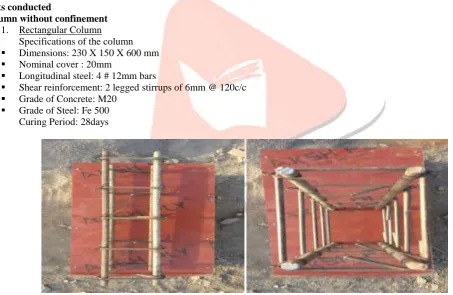
Column without confinement 1. Rectangular Column
Specifications of the column Dimensions: 230 X 150 X 600 mm Nominal cover : 20mm
Longitudinal steel: 4 # 12mm bars
Shear reinforcement: 2 legged stirrups of 6mm @ 120c/c Grade of Concrete: M20
Grade of Steel: Fe 500 Curing Period: 28days
Fig 1.Arrangement of reinforcement
2.Square Column
Specifications of the column
Dimensions: 190 X 190 X 600 mm Nominal cover : 20mm
Longitudinal steel: 4 # 12mm bars
Shear reinforcement: 2 legged stirrups of 6mm @ 120c/c Grade of Concrete: M20
IJEDR1702214
International Journal of Engineering Development and Research (www.ijedr.org)1371
Fig.2 Binding of Reinforcement for square columnColumn with confinement Rectangular and square column
The specifications of the rectangular And square column with confinement are the same as compare to the without confinement.
The only changes is the welded wire mesh to be used is of 1 inch spacing Binding of reinforcement with welded wire mesh for confined rectangular column
Fig.3. Reinforcement binding with welded wire mesh for rectangular column.
IJEDR1702214
International Journal of Engineering Development and Research (www.ijedr.org)1372
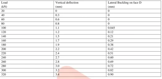
TEST 1 COLUMN WITHOUT CONFINEMENTResults:-
Table no. 3.1 Observations of Test 1 Load
(kN)
Vertical deflection (mm)
Lateral Buckling on face D (mm)
20 0 0
40 0.3 0
60 0.6 0
80 0.8 0
100 1.1 0.045
120 1.2 0.12
140 1.5 0.21
160 1.7 0.29
180 1.9 0.38
200 2.2 0.42
220 2.4 0.51
240 2.7 0.60
260 2.8 0.69
280 3.0 0.72
300 3.2 0.82
320 3.4 0.90
Conclusion: - The test was conducted for the column without confinement reinforcement. The test was carried up to the yield point and it was observed that the first crack on the surface of the concrete occurs at 320 kN load. At this point the vertical deflection was observed as 3.4 mm and the lateral deflection was 0.9 mm on the face D of the column.
TEST 2: Column with welded wire mesh as confinement reinforcement
Specifications of the column:- Dimensions: 230 X 150 mm Longitudinal steel: 4 # 12mm bars
Shear reinforcement: 2 legged stirrups of 6mm @ 125c/c Grade of Concrete: M20
Grade of Steel: Fe500 Curing Period: 14days
Specifications of Confinement reinforcement: Spacing of welded wire mesh is 1” Faces of the Columns are named as A, B, C & D
Table no. 3.2 Observations of Test 2
Load (kN)
Face A
Deflection(mm)
Face B
deflection(mm)
Face C
deflection(mm)
Face D deflection(mm)
0 0 0 0 0
20 0 0 0 0
40 0 0 0 0
60 0 0 0 0
80 0 0 0 0
100 0 0 0 0
120 0 0 0 0
140 0 0 0 0
160 0.1 0 0 0
180 0.1 0 0 0
200 0.17 0 0 0
IJEDR1702214
International Journal of Engineering Development and Research (www.ijedr.org)1373
240 0.18 0 0 0
260 0.20 0 0 0
280 0.25 0 0 0
300 0.26 0 0 0
320 0.26 0 0 0
340 0.30 0 0 0
360 0.31 0 0 0
380 0.32 0 0 0
400 0.33 0.02 0 0
420 0.34 0.08 0 0
440 0.34 0.1 0 0
460 0.35 0.1 0 0
480 0.35 0.11 0 0
500 0.34 0.19 0 0
520 0.30 0.26 0 0
540 0.25 0.30 0.01 0
560 0.20 0.35 0.06 0
580 0.10 0.40 0.10 0
600 0 0.46 0.27 0
620 0 0.0 2.6 0.5
640 0 0.0 4.5 0.5
Discussion on Results
The test was conducted for the column with confinement reinforcement as welded wire mesh with 25.4 mm spacing. The test was carried up to the ultimate point and it was observed that the first crack on the surface of the concrete occurs at 440 kN load and the ultimate load taken by the column is 655 kN. At this point the vertical deflection was observed as 10.8 mm and the lateral deflection is as shown in Table 3.2
REFERENCES
1. N. Subramanian, “design of confinement reinforcement” Indian Concrete Journal. 2. S Watson, “confining reinforcement concrete column” ASCE.
3. Georges, Stathis, “experimental study of effect of confinement on the RC column”.
4. Confinement reinforcement design for reinforced concrete columns p. Paultre, m.ASCE1; and F. Légeron, m.ASCE2. 5. Watson S., Zahn, F. A., and Park, R., “Confining Reinforcement for Concrete Columns,” Journal of Structural
Engineering, Vol. 120, No. 6, June 1994, pp.1798-1824.
6. Abdullah and Takiguchi, K. (2003), “An investigation into the behavior and strength of reinforced concrete columns strengthened with Ferro cement jackets”. Cement & Concrete Composites, vol. 25: pp 233–242.
7. Shetty R.K. and Jain A.K., “Special confinement reinforcement in RC Columns and shear walls”, The Indian Concrete Journal, Vol. 85, No.6, June 2011, pp. 19-29.
8. Mander, J. B., Priestley, M. J. N., and Park, R. (1988a). “Theoretical stress strain model of confined concrete.” J. Structural. Engineering., 114(8), 1804–1826.
9. Ilki, A., Kumbasar, N., Ozdemir, P., and Fukuta, T. (2004). “A trilinear stress-strain model for confined concrete.” Struct. Eng. Mech., 18(5), 541–563.