Practical considerations on optimising multistage
decimation and interpolation processes
Xiangyu Zhu
1, Yonghao Wang
1, Wei Hu
2,3, Joshua D. Reiss
41DMT Lab, Birmingham City University, UK
2College of Computer Science and Technology, Wuhan University of Science and Technology, China 3Hubei Province Key Laboratory of Intelligent Information Processing and Real-time Industrial System, China
4Centre for Digital Music, Queen Mary University of London, UK
[email protected], *[email protected], [email protected], [email protected]
Abstract—Multistage filter design is a complex multidimensional optimisation problem. The formulae for optimal design generally yield non-integer real numbers for the sample-rate-changing factors of multiple stages. Approaches yielding useful integer results have high computational cost and do not consider important multistage filter design properties. We have developed a simplified algorithm for directly searching the optimal integer results. Considering the most useful practical design parameters, optimal results can be approximated with a limited number of sets for any designs satisfying certain constraints, with negligible costs. This vastly simplifies the complexity of the problem.
Keywords: Multistage, filter design, FIR, decimation, interpolation.
I. INTRODUCTION
Oversampling and sigma-delta based converters have become popular in digital audio applications due to their high resolution and low hardware cost [1] [2] [3]. Most modern digital audio systems include some sample rate conversion processes in either software format or integrated circuits. The key components of sampling rate alteration are the decimation or interpolation filters, which alter the sampling rate and suppress unwanted digital aliasing and imaging, respectively.
The multistage filter structure can be up to 10 times more efficient than a single stage structure. Reference [4] [5] presented the theory and quantification of cost optimisation of multistage structures. Reference [6] [7] found that optimal solutions can be derived analytically by taking the partial differential equation (PDE) of the cost function, hence reducing it to a one dimensional problem without needing complex numerical search algorithms. However optimal solutions are often groups of non-integer real numbers that cannot be implemented in practical systems. Manual adjustment of results is needed, one still needs to retreat to numerical methods to solve the equations, and for each design, the roots of the equation must be put back into a cost function to find the optimal solution set. Alternatively, one can yield the integer solution directly. Reference [8] represents this problem in the integer domain using set theory, and then performs integer factorization. Reference [9] showed that the problem can be solved using exhaustive search or a genetic algorithm.
We show that properties of solutions allow simplification of the search algorithm (Section II). Based on distribution of the solution sets, we propose a new search algorithm and use it to generate optimal solution lookup tables for practical designs
(Section III). A balanced trade-off strategy is developed to find a best solution set for both computational and memory area cost (Section IV). Conclusions are given in the last section.
II. DESCRIPTION OF THE BACKGROUND THEORY
The digital FIR filter design with very narrow transition band, high attenuation stopband and flat passband results in large order filters. The digital anti-aliasing and anti-image filters used in oversampling based high resolution ADC/DAC belong to this category [10] [11]. The classical approach is to use multistage design so that the design specification of each individual filter (stage) can be relaxed. Given the overall sampling rate changing factor 𝐷, each stage in a K stage filter alters the sampling rate by 𝐷𝑖 where 𝐷 = ∏𝐾𝑖=1𝐷𝑖. For a K
stage filter and given design specifications, the problem is to find the set {𝐷𝑖} such that D is optimal in terms of computation
or memory area cost.
Let 𝛿𝑝 and 𝛿𝑠 represent the tolerance in the magnitude
response in the passband and stopband respectively. ∆𝑓 =
𝑓𝑠−𝑓𝑝
𝑓𝑠 , where 𝑓𝑠 is the stopband edge and 𝑓𝑝 is the passband edge, and 𝑓𝑟0 is the input signal’s sampling frequency. The
computational cost 𝑅𝑇 is the total number of multiplies and
adds per second(𝑀𝐴𝐷𝑆/𝑠), and given by (1) [4] [5].
𝑅𝑇 = 𝐷∞(
𝛿𝑝
𝐾, 𝛿𝑠) 𝑓𝑟0𝑆 (1)
Where
𝐷∞(𝛿𝑝, 𝛿𝑠) = [5.309 × 10⁻³(𝑙𝑜𝑔10𝛿𝑝) 2
+ 7.114
× 10−2(𝑙𝑜𝑔
10𝛿𝑝) − 0.4761] 𝑙𝑜𝑔10𝛿𝑠
− [2.66 × 10⁻³(𝑙𝑜𝑔 10𝛿𝑝)
2
+ 0.5941(𝑙𝑜𝑔10𝛿𝑝) + 0.4278]
(2)
𝑆 = 2 Δ𝑓
1 ∏𝐾−1𝑗 = 1𝐷𝑗
+ ∑ 𝐷𝑖
(∏𝑖𝑗=1𝐷𝑗)(1 − (
2 − ∆𝑓
2𝐷 ) ∏𝑖𝑗=1𝐷𝑗) 𝐾−1
𝑖=1
(3)
The total memory storage cost of such a filter is given by
𝑁𝑇 = 𝐷∞(
𝛿𝑝
Where 𝐺 is a proportionality constant that relates to the implementation of filter coefficients and 𝑇 is given by
𝑇 = 2 ∆𝑓
𝐷 ∏𝐾−1𝑗=1𝐷𝑗
+ ∑ 𝐷𝑖
1 − 𝛼 ∏𝑖𝑗=1𝐷𝑗 𝐾−1
𝑖=1
(5)
where α = 2−∆𝑓
2𝐷 .
To minimise 𝑅𝑇 is to minimise 𝑆 in (3) and to minimise 𝑁𝑇
is to minimise 𝑇 in (5). 𝑆 and 𝑇 are only dependent on the 𝐷𝑖
and ∆𝑓.
Reference [6] and [7] took a PDE approach to cost functions (3) and (5), treating 𝐷𝑖 as continues real value. For
example, finding 𝐷1 in a 3-stage design can be formulated as a
roots finding problem:
𝜕𝑇 𝜕𝐷1
= − 2𝐷 ∆𝑓𝐷12𝐷2
+ 1
(1 − 𝛼𝐷1)2
+ 𝛼√2𝐷 ∆𝑓
1 𝐷1
𝐷2= 0 (6)
Often solving (6) requires numeric methods and results in complex and irrational roots.
Reference [8] and [9] directly search integer sets of {𝐷𝑖}
that are factors of 𝐷, using exhaustive search or a genetic algorithm to produce integer valued optimal results, but did not taking the properties of the real valued solution into account.
In this work, we observe the distributions of both real valued and integer valued optimal solution sets. We find both of these follow certain regular patterns. This enables us to vastly simplify the optimisation problem and the size of the problem. The findings are discussed in the following section.
III. KNOWLEDGE-BASED SEARCH AND LOOKUP TABLES
Observing from the experiments’ results of both real-valued and integer valued optimal solutions, there are three important properties of the distributions of optimal solutions for both optimal computational cost and memory storage cost:
a) {𝐷𝑖} is always in descending order for multistage
decimation and in ascending order for multistage interpolation.
The larger value of 𝐷𝑖 means the larger decimation or
interpolation factors stage 𝑖. In order to minimise the narrow transition band effects on high sampling frequency (oversampled), it is understandable to have larger 𝐷𝑖 close to
the higher sampling frequency end.
The experiments show that the average real valued solution of smallest value of 𝐷𝑖for 3-stage design is around 2.65 (𝐷3)
and for 4-stage design is around 1.52 (𝐷4) for decimation
process. These number is close to integer number 2 that is the minimum sampling rate changing factor, and is close to the lowest sampling frequency stage.
b) 𝛥𝑓 is related to the width of transition band. The variation of 𝛥𝑓 changes the order of the filter but not the sampling rate changing factor of each stage.
This is because for same overall value D,the distribution of 𝐷𝑖 still follows the trend of property a) regardless of filter
order. According to [6] [7], ∆𝑓 has only a small effect on the results. Also because the results are not integer, rounding is needed and often, the difference due to using different ∆𝑓 is smaller than the difference caused by the rounding process.
c) Because of a), we need to test the optimal set by cost functions only for highly composite number (non-prime) D that can be factorised more than number of stages K.
Thus, search for integer valued solutions can be informed by a), and because of b) and c), the problem size is considerably small than it appeared to be.
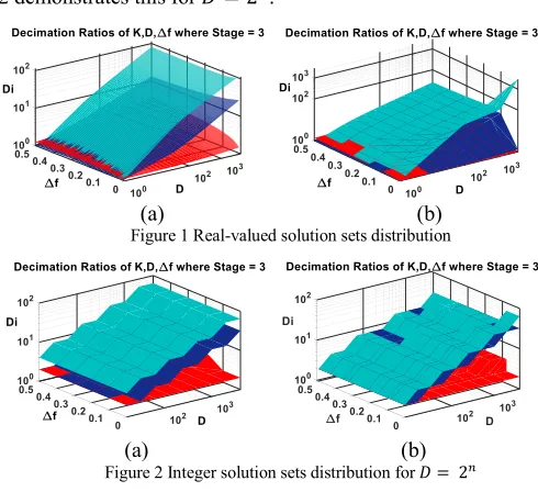
Fig.1 shows 3D plots of the 3 stage real-valued optimal solution distribution for optimising 𝑅𝑇 (Fig.1.a) and 𝑁𝑇 (Fig.
1.b). The real valued optimal result sets {𝐷1, 𝐷2, 𝐷3} are
formed from three independent disjoint surfaces with different 𝐷<5000 and 0<Δ𝑓<0.5. The values of lowest surface is close to the minimum value of interpolation and decimation factor 2. The optimal integer valued solutions follow a similar trend. Fig 2 demonstrates this for 𝐷 = 2𝑛.
(a) (b)
Figure 1 Real-valued solution sets distribution
(a) (b)
Figure 2 Integer solution sets distribution for 𝐷 = 2𝑛
The simplified search algorithm is described in Table I: TABLE I PSEUDOCODE OF OPTIMAL INTEGER VALUED SOLUTION
SEARCH ALGORITHM
For 𝐷 ∈ ℕ1 and represented as a prime factorization:
𝐷 = 𝑝1𝑑1∗ 𝑝
2 𝑑2∗ 𝑝
3 𝑑3… ∗ 𝑝
𝑟 𝑑𝑟
where 𝑝𝑖 is a prime number and 𝑑𝑖 the corresponding
exponent,
1) Check whether 𝐷 can be factorized into 𝑀 unique sets of 𝑘 (stage) factors
𝑀 = {
{𝐷1.1, 𝐷2.1, … 𝐷𝑘.1}
{𝐷1.2, 𝐷2.2, … 𝐷𝑘.2}
⋮
{𝐷1.𝑚, 𝐷2.𝑚, … 𝐷𝑘.𝑚}
}
2) Sort 𝑀 so that {𝐷𝑖.1 > 𝐷𝑖.2 > ⋯ > 𝐷𝑖.𝑘}
3) Substitute sets into (3) or (5) and find the set with the minimum solution.
we sort candidate sets as descending ordered sequences. Only when the number of D’s factors is larger than the required number of stages, the step 2) sorting required. For example, for 𝐷<5000, 3 stage decomposition, only 1692 (33.8%) numbers can be factorised in different unique sets of 3 factors that need to be put back into the cost function. For typical design value ∆𝑓 = 0.18 and D<5000 and 2, 3, 4 stage design, our method provides 85.4% average reduction when compared with exhaustive search in terms of the number of cost function tests, and 65% computing time reduction. Computing time was averaged over 100 iterations using a standard Intel Core i7 based PC.
In addition, the variation of ∆𝑓 does not cause much change in the optimal integer values. For the same example of 𝐷<5000 and 3 stage case, within the 1692 cases that have possible multiple solutions, in 994 (59%) cases for computational cost optimisation and 1167 (69%) cases for memory cost optimisation, the optimal solution sets change only once or twice over the (0 to 0.5) ∆𝑓 region.
Table II summarises 15 popular ADC/DAC chipsets used in audio devices from on-board sound cards to professional mixers. The supported sampling frequencies 𝐹𝑠 range from 44.1
kHz, 48 kHz, 96 kHz with different supported filter type configurations such as low latency, sharp or slow roll off, etc. Δ𝑓 is within 0.08-0.44 with most common designs between 0.15 and 0.4.
TABLE II SUMMARY OF 𝛥𝑓 VALUES OF COMMON OVERSAMPLING BASED AUDIO ADC/DAC DESIGN SPECIFICATIONS
Type Max 𝒇𝒑 Min 𝒇𝒔 Min ∆𝒇
AD1871 0.45 𝐹𝑠 0.55 𝐹𝑠 0.17 AD7768 0.43 𝐹𝑠 0.50 𝐹𝑠 0.14 AD1974 0.44 𝐹𝑠 0.56 𝐹𝑠 0.21 ADAU1966A 0.36-0.45 𝐹𝑠 0.55-0.64 𝐹𝑠 0.18-0.44
PCM1807 0.45 𝐹𝑠 0.58 𝐹𝑠 0.22 PCM4220 0.42-0.45 𝐹𝑠 0.55-0.58 𝐹𝑠 0.18-0.28 PCM1794A 0.46-0.49 𝐹𝑠 0.55-0.73 𝐹𝑠 0.11-0.37 PCM5242 0.40-0.47 𝐹𝑠 0.55 𝐹𝑠 0.15-0.18 CS5364/66/68 0.45-0.47 𝐹𝑠 0.58-0.68 𝐹𝑠 0.19-0.34 CS5381 0.45-0.47 𝐹𝑠 0.58-0.68 𝐹𝑠 0.19-0.34 CS4398 0.499 𝐹𝑠 0.55-0.58 𝐹𝑠 0.09-0.14 WM8740 0.27-0.45 𝐹𝑠 0.46-0.49 𝐹𝑠 0.08-0.41 WM8741 0.4 𝐹𝑠 0.5 𝐹𝑠 0.2
ALC885 0.45 𝐹𝑠 0.60 𝐹𝑠 0.25 CS4207 0.45-0.499 𝐹𝑠 0.55-0.60 𝐹𝑠 0.09-0.25
We use a bisection method to find the ∆𝑓 points where optimal solutions change. For common 2, 3, 4 stage filter design, two groups of lookup tables for computational and area costs can be generated from the algorithm. They are small since optimal solutions are smooth over useable design specification ranges.
Fig. 3 shows changing of optimal solution sets {𝐷𝑖} against
D and f. The Z axis value is calculated from (7), where ω is a weighting factor, and σ(𝐷𝑖, 𝐾) is the standard deviation of
optimal set {Di}. It provides information regarding both ∏ 𝐷𝑖
and the distribution value of 𝐷𝑖 within a solution set. Since the
elements of set {𝐷𝑖} are descending or ascending,
σ(𝐷𝑖, 𝐾) indicates the slope of the value changing across stages.
The same value of Z indicates same set of {𝐷𝑖} being chosen.
𝑍 = ω 𝐷 + σ(𝐷𝑖, 𝐾) (7)
Figure 3 Changing of optimal value against ∆𝑓 for some highly composite number 𝐷
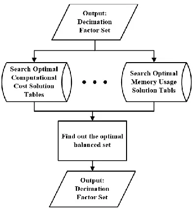
Fig. 3 shows that optimal integer solution sets can be the same values for a large range of design specification f. Similar figures can be produced for both optimal area cost and computational cost sets. Thus, we can create lookup tables to store these optimal solutions with the critical values of f that cause changes in optimal solution sets. The structure of a database of such tables is depicted in Fig. 4. Using our algorithm to generate K= 2, 3, 4 stage design tables for both memory and computational cost, with 1<D<5000 and 0<∆𝑓<0.5, there are 15,783 total optimal computational cost sets and 17,622 total optimal memory usage sets in the three tables.
Figure 4 depiction of optimal solution sets lookup tables of computational cost or memory storage cost
IV. TRADEOFF STRATEGY FOR MINIMISATION OF BOTH AREA AND COMPUTATIONAL COST
In practise, only one solution can be used in a system. A trade-off strategy based on error effects was developed to find a best solution set for both computational and memory area cost within the lookup tables.
when {𝐷𝑖}𝑚≠ {𝐷𝑖}𝑐
if 𝐶𝑚−𝐶𝑐
𝐶𝑐 >
𝑀𝑐−𝑀𝑚
Where:
{𝐷𝑖}𝑐 is the integer valued solution set for optimal
computational cost.
{𝐷𝑖}𝑚is the integer valued solution set for optimal memory
usage cost.
𝐶𝑐 is computational cost with optimal computational cost
set.
𝐶𝑚 is computational cost with optimal memory usage set.
𝑀𝑐 is memory usage with optimal computational cost set.
𝑀𝑚 is memory usage with optimal memory usage set.
To evaluate the error effects of this trade-off strategy, we evaluated the average error of computational cost: 𝑆𝑑𝑖𝑓𝑓=
(∑ 𝐶𝑖−𝐶𝑐𝑖
𝐶𝑐𝑖 𝑁
𝑖=1 )/𝑁, and the average error of memory cost:
𝑇𝑑𝑖𝑓𝑓= (∑
𝑀𝑖−𝑀𝑚𝑖 𝑀𝑚𝑖 𝑁
𝑖=1 )/𝑁, where 𝑁 is total number of design
cases tested; 𝐶𝑖 and 𝑀𝑖 are the actual computational cost and
memory usage when the trade-off sets being used; 𝐶𝑐𝑖 and 𝑀𝑚𝑖
are the computational cost and memory usage when the corresponding optimal sets being used.
For 3 stage design with 0<∆𝑓<0.5 and 0<D<5000, the average error is 0.26% for 𝑆𝑑𝑖𝑓𝑓 and 8.88% for 𝑇𝑑𝑖𝑓𝑓.
Figure 5 Follow chart of overall database query algorithm
Fig. 5 shows the flowchart for finding semi-optimal solutions for both constraints. It is worth mentioning that this method can be altered with extra weighting factor to consider actual implementation effects. The design parameter Δ𝑓, 𝐷 and different platform realisation techniques might have influence of actual selection decisions. Further work needs to be done to decide the form of weighting factor.
CONCLUSION
We provided new experimental results and analysis concerning optimal multistage multirate FIR filter design. The results show that the optimal solution set possesses important properties that allow for knowledge-based search, and that the
number of optimal solution sets are limited since they do not change the set values over a large range of design specifications. This motivates the design of multiple lookup tables of solution sets. A trade-off strategy is employed to produce semi-optimal solution sets that reduce computational and memory usage costs.
Our approach was derived based on classical individual optimal FIR filter design [12] in terms of theoretical number of multiplies and adds needed, and the memory storage for storing signal samples and filter coefficients. There are a set of different filter computation reduction methods based on creating one-stage two-filters system where one filter B(z) shapes the passband and another filter A(z) shapes the stopband. The passband filter B(z) works at lower sampling rate of multirate system . It will be interesting to investigate how their work performs at very high sampling rate alteration D in comparison with this work [13] [14] [15]. Other research has looked into further bit-level optimisation of filter coefficients in a multistage architecture [16] [17], and specific application cases [18] [19]. It would be interesting to see how the optimal filter can be applied to those cases. The number of stages and their rate changing factors also affect filter latency [20], and computational cost, memory usage and their realisation methods affect the energy consumption. An interesting research direction would be to look into a model that considers these additional aspects of optimal multistage design.
ACKNOWLEDGMENT
The algorithms herein are available under MIT open source license from https://github.com/wyonghao/MultiStageDesign.
REFERENCES
[1] W. Kester, “A Brief History of Data Conversion: A Tale of Nozzles, Relays, Tubes, Transistors, and CMOS,”IEEE Solid-State Circuits Magazine, vol. 7, no. 3, pp. 16-37, Summer 2015.
[2] S. Norsworthy, et al. “Delta-sigma data converters: theory, design, and simulation” IEEE press New Jersey,. Ch13, p 406-446, 1996
[3] Kester, W. Mixed-Signal and DSP Design Techniques. Norwood, MA: Analog Devices, Ch. 3, pp. 16–17. 2000
[4] R. Crochiere and L. Rabiner, “Optimum FIR digital filter implementations for decimation, interpolation, and narrow-band filtering”, IEEE Trans. Acoust. Speech Signal Process., v. 23, no. 5, pp. 444 – 456, Oct. 1975.
[5] R. E. Crochiere and L. Rabiner, “Interpolation and decimation of digital signals - A tutorial review”, Proc. IEEE, vol. 69, no. 3, pp. 300–331, 1981.
[6] M. W. Coffey, “Optimizing multistage decimation and interpolation processing”, IEEE Signal Process. Lett., vol. 10, no. 4, pp. 107–110, 2003.
[7] M. W. Coffey, “Optimizing Multistage Decimation and Interpolation Processing mdash;Part II”, IEEE Sig. Proc. Lett., 14 (1), pp. 24–26, 2007. [8] Der-Feng Huang, “The direct integer factorization approach to the
Crochiere and Rabiner multistage FIR designs for multirate systems”, 3rd Int. Symp. Image Sig. Proc. Analysis (ISPA), v. 2, p1060–65, 2003. [9] D.-F. Huang & S.-R. Hung, “The optimum design of multistage
multirate FIR filter for audio signal sampling rate conversion via a genetic algorithm approach”,2nd Int. Cong. Image Sig. Proc. (CISP), 2009
[10] Lesso, P. and Magrath, A. J. “An Ultra High Performance DAC with Controlled Time-Domain Response” 119th AES Conv. 119, Oct. 2005
[11] Craven, Peter G. “Antialias Filters and System Transient Response at High Sample Rates.” Journal of the Audio Engineering Society 52.3, 2004
[13] T. Saramäki, “A New Class of Linear-Phase FIR Filters for Decimation, Interpolation, and Narrow-Band Filtering,” Proc. IEEE Int. Symp. Circuits Syst., pp. 808–811, Rome, Italy, May 10–12, 1982
[14] T. Saramäki, “A class of linear-phase FIR filters for decimation, interpolation, and narrow-band filtering,” IEEE Transactions on Acoustics, Speech, and Signal processing, vol. ASSP–32, no. 5, pp. 1023–1036, October 1984.
[15] P. Arian and T. Saramäki, “A systematic technique for optimizing one-stage two-filter linear-phase FIR filters for sampling rate conversion,” in Proc. 2003 IEEE International Symposium on Circuits and Systems, Bangkok, Thailand, May 25–28, 2003, vol. 4, pp. 197–200.
[16] A. Blad et al, “Bit-level optimized FIR filter architectures for high-speed decimation applications,” IEEE Int. Symp. Circ. Syst., Seattle, 2008.
[17] A. Shahein, et al, “A Novel Hybrid Monotonic Local Search Algorithm for FIR Filter Coefficients Optimization,” IEEE Trans. Circ. Syst. I: Regular Papers, 59 (3), p 616-627, March 2012.
[18] M. Mottaghi-Kashtiban, et al, “Optimum Structures for Sample Rate Conversion from CD to DAT and DAT to CD Using Multistage Interpolation and Decimation,” IEEE Int. Symp. Sig. Proc. Inf. Tech., Vancouver, 2006
[19] S. Liu, W. Jiang, and M. Zhang. “Dual-channel multiplexing technology and its realization in interpolation filter in stereo audio sigma-delta DAC”. Analog Integrated Circuits and Signal Processing, 81 (2), Nov. 2014