Volume-7 Issue-2
International Journal of Intellectual Advancements
and Research in Engineering Computations
Design of fixture for angular pipe cutting and its product failure analysis in
root cause analysis
N. Senniangiri
1, T. Ajith kumar
2, M. Bharathi
2, P. Hariharan
2, J. Kavin
21
Assistant Professor,
2UG Students
Department of Mechanical Engineering, Nandha College of Technology, Erode-52, Tamil Nadu, India
ABSTRACT
This paper represents the design andanalysis of the fixture for angular pipe cutting. In last few decades fixture is being used in the industries as an work-holding device. Ordinary fixtures that have been used in past few decades was tedious one and requires more time for fixing the work piece. And the measurement in the work piece has to be marked before fixing the job in the fixture. It requires more time and sometimes production may be delayed. This angular cutting fixture designed on the basis on elimination of marking and helps in mass production. This angular cutting fixture is used in cutting and milling process. This fixture is to all type of cutting machine and CNC also. We can cut the pipe in accurate angle and dimension. By usi ng this accurate dimension can be easily machined.
Keywords:
Fixture, Work holding device. Production improved, Reduction in time and good accuracy dimension.INTRODUCTION
A fixture is a work-holding or support device used in the manufacturing industry. Fixtures are used to securely locate (position in a specific ----location or orientation) and support the work, ensuring that all parts produced using the fixture will maintain conformity and interchangeability. Using a fixture improves the economy of production by allowing smooth operation and quick transition from part to part, reducing the requirement for skilled labor by simplifying how work pieces are mounted, and increasing conformity across a production run.
A fixture differs from a jig in that when a fixture is used, the tool must move relative to the work piece; a jig moves the piece while the tool remains stationary. A fixture’s primary purpose is to create a secure mounting point for a work piece, allowing for support during operation and increased accuracy, precision, reliability and interchangeability in the finished parts. It also serves to reduce working time by allowing quick
set-up, and by smoothing the transition from part to part. It frequently reduces the complexity of a process, allowing for unskilled workers to perform it and effectively transferring the skill of the tool maker to the unskilled worker.
Fixtures also allow for a higher degree of operator safety by reducing concentration and effort required to hold a piece steady.
Economically speaking the most valuable function of a fixture is to reduce labour costs. Without a fixture, operating a machine or process may require two or more operators; using a fixture can eliminate one of the operators by securing the work piece.
PROBLEM DESCRIPTION
The comparative study has been carried out the performance of the angular cutting .In normal cutting machine we can change the head for required angle. Change the head angle the accuracy is not good and time consuming is high to
manufacturing the product .machine cost is high in cutting or milling machine the angle deviation is formed in changing the head.
Method of Solution
We can design the fixture for required angle fixture is fixed in the machine increase the productivity in less time . and cannot change the machine head accuracy of dimension in accurate using the fixture.
LITERATURE REVIEW
1. Nikhil G. Lokhande, Department of mechanical Engineering.The fixture includes a base having angular cutting for receiving larger cylindrical work pieces, a pair of smaller cutting openings in
the side walls of the base for receiving smaller cy-lindricalwork pieces, a cover attached to the base and a rotatable, index-able fixture mounted to the cover.
2. Tembhurkar . CK Mechanical engineering. This invention relates to a cutting fixture for accurate positioning of cutting tool and control of the direction during cylindrical shaped surfaces either on or off center.
3. T. Pulkkinen, This device consist of a one piece, uniformly square metal cube having all corners chamfered at a 39.81 degree angle to provide a corner with curicular surface to yield an 18 sided symmetrical polygon. Seventeen of the side provided with angle cutting of different sizes with parallel to the center line of two opposite and parallel surface of the cube.
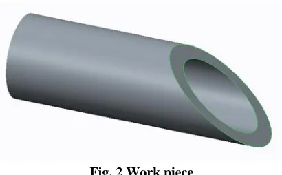
DESIGN OF WORK PIECE
Fig.1 Drafting view of work piece
Work piece is a hollow cylindrical pipe shape.
ANGLE CALCULATION
tanα=(opp/adj)
α=tan˄(-1)(opp/adj) =tan˄(-1)(45/54) =tan˄(-1)(0.8333) α =39.81
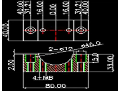
FIXTURE DESIGN
Fixtures must always be designed with economics in mind; the purpose of these devices is to reduce costs, and so they must be designed in such a way that the cost reduction out weights the cost of implementing the fixture. It is usually better, from an economic standpoint, for a fixture to result in a small cost reduction for a process in constant use, than for a large cost reduction for a process used only occasionally. Most fixtures have solid components, affixed to the floor or to the
body of the machine and considered immovable relative to the motion of the machining bit, and one or more movable components known as clamps. These clamps (which may be operated by many different mechanical means) allow work pieces to be easily placed in the machine or removed, and yet stay secure during operation. Many are also adjustable, allowing for work pieces of different sizes to be used for different operations. Fixtures must be designed such that the pressure or motion of the machining operation (usually known as the feed) is directed primarily against the solid component of the fixture.
This reduces the likelihood that the fixture will fail, interrupting the operation and potentially causing damage to infrastructure, components, or operators.
Fig. 4 Drafting of locator top view
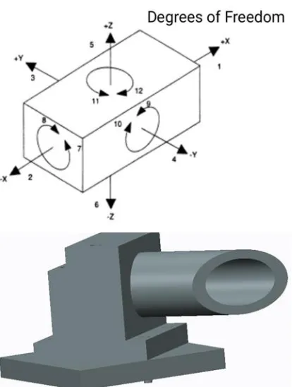
Fig. 5 Assemble view of fixture and work piece
Degrees of freedom is used to assemble the fixture in moving direction the fixture top locator only move in up and down.
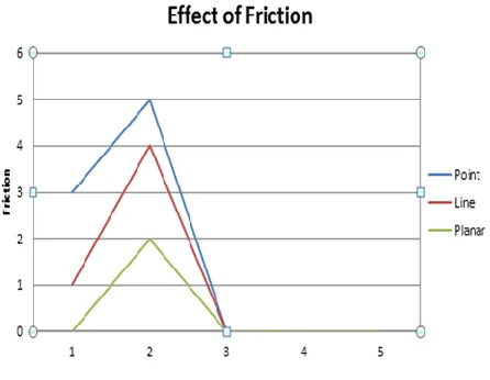
EFFECT OF FRICTION
Impact of friction on the degrees of freedom allowed by different contact types is as follows:
Contact type Friction No Friction
No friction
ROOT CAUSE ANALYSIS
Cutting angle is deviation to analysis the product piece and we can choose the friction to reduce the angle deviation and cost.
Milling without fixture Milling with fixture
Time requirement is about 30mins Time requirement is about 5mins
Cost is about Rs.35/- piece Cost is about Rs.10/-piece
Fig. 6 Cause and effect or fishbone diagram
Analysis the product most problem is angle deviation and machining use fixture to reduce the problem and analysis
RESULT AND DISCUSSION
The analysis is done for three force of attack such as 1Newtone, 10Newtone, 100Newtone
respectively for both the work piece and fixture
Fig-8: Static Structure Total Deformation
The static structure of total deformation is done by 10 Newton .The maximum stress in 1.5695e-11Max. The red colour is defect occurred
Fig-9: Static Structure Analysis
The fixture was design and analysis. In work piece the cutting position is red colour it was more head and stress.
CONCLUSIONS
There are not many fixtures available for angular cutting in to-day’s scenario. As application for fixture design differs from industry to industry because dimensions required by industries differ from each other. This simple design of cutting fixture assembly enables to perform such operation
with accuracy and repeatability by attaching U- CAM.
After analyzing the cutting by Finite element method by considering axis symmetric loading, the results obtained are validating with Ansys results. Problems involving three dimensional axis symmetric solids subjected to axis symmetric loading reduce to two dimensional problems. Because of total symmetry about z axis all deformations and stresses are independent of rotational angle.
REFERENCES
[1]. Boyle IM, Rong K, Brown DC “CAFixD: A Case-Based ReasoningFixture design method. Framework and Indexing Mechanisms”. J ComputInfSciEng 6, 2006, 40.
[2]. klee G, De Noma GR, Collier SL, Newman RJ Drilling fixture 1984.