e-ISSN: 2250-3021, p-ISSN: 2278-8719 Vol. 3, Issue 6 (June. 2013), ||V2|| PP 14-18
A Low Cost Fly back Continuous Conduction Mode Inverter
With Lcl Filter For Ac Module Application
Steffi Sharoffa.M,
1Cordelia Sumathy.A
2,
2, Associate Proffessor , Francis Xavier Engg College, Tirunelveli.1, PG scholar, Francis Xavier Engg College, Tirunelveli
Abstract:- This paper presents a method to improve the efficiency by operating the flyback inverter in
continuous conduction mode with sliding mode controller for Ac module application. The unfolding type flyback inverter operating in discontinuous conduction mode is the conventional method used for low cost solution for photovoltaic AC application. In this proposed method we have aimed to get an improved efficiency compared with conventional method by using continuous conduction mode flyback inverter with sliding mode controller and the output power quality at rated power level is improved by connecting LCL filter between the inverter and load.
Photovoltaic (PV), or solar cells as they are often used for Ac module application, they are used here to convert sunlight into direct-current (DC) electricity.MPPT or Maximum Power Point Tracking algorithm is included in sliding mode controllers used for extracting maximum available power from PV module under certain conditions. Normally, the DC output voltage produced by PV panel is very low which is converted into high AC voltage by using flyback inverter. The main advantage of the flyback inverter is , it does not require any additional circuit to convert the low output voltage of PV panel into high voltage because it has capability to step up the voltage.
I. INTRODUCTION
Nowadays the fossils fuel deficit, skyrocketing oil prices, global warming, and damage to environment and ecosystem are increasing, the promising incentives to develop alternative energy resources with high efficiency and low emission are of great importance. Among the renewable energy resources, the energy through the photovoltaic effect can be considered the most essential and prerequisite sustainable resource because of the ubiquity, abundance, and sustainability of solar radiant energy. Regardless of the intermittency of sunlight, solar energy is widely available and completely free of cost.Recently photovoltaic array system is likely recognized and widely utilized to the forefront in electric power applications. It can generate direct current electricity without environmental impact and contamination when is exposed to solar radiation. Being a semiconductor device, the PV system is static, quite, and free of moving parts, and these make it have little operation and maintenance costs. Even though the PV system is posed to its high capital fabrication cost and low conversion efficiency, the skyrocketing oil prices make solar energy naturally viable energy supply with potentially long-term benefits.
The PV panel with a module-integrated inverter, called an “ac module”, which directly serves the grid. Also, only ac cable wiring is needed, which simplifies the installation.
For this ac module application, selection of inverter is an important one. In this project in order to improve the efficiency flyback inverter is designed and it is operated in continuous conduction mode
In the conventional method an isolated cascaded scheme that includes one or more dc voltage boosting stage and a conventional full bridge PWM inverter. This type of inverter has by far the highest reported efficiencies compared to other isolated inverters. Also, the electrolytic capacitor for power decoupling can be replaced by a higher voltage film capacitor with longer lifetime. However, the penalty paid for this approach is more component count and hence higher cost. Considerations of reducing the cost have led to a next approach based on an unfolding type inverter. Here, the voltage boosting, isolation and output current shaping are all performed by a dc-dc converter that is then followed by a low frequency unfolding stage. A flyback inverter with center tapped secondary windings is often leading to simple overall system. However, in this, scheme, the flyback is operated in the discontinuous conduction mode resulting in high current stress and lower efficiencies .This is particularly true in low voltage and high current applications such as ac module under consideration. When operated continuous conduction mode, a flyback converter has lower peak currents and hence higher efficiencies.
inverter applications. This may have prevented the use of the flyback continuous conduction mode converter in dc ac applications. Therefore in our approach , we investigate the feasibility of a flyback inverter operating with LCL filter in order to reduce the total harmonic distortion and sliding mode controlled maximum power point tracking scheme is also included.
II. PV SYSTEMS
Photovoltaic‟s offer consumers the ability to generate electricity in clean, static and reliable way. Photovoltaic‟s systems are comprised of photovoltaic cells devices that convert light energy directly into electricity. Because the source of light is usually the sun, they are often called solar cells. The word photovoltaic comes from “photo”, meaning light, and “voltaic “, which refers to producing electricity therefore, the photovoltaic process is producing electricity directly from the sunlight. Photovoltaic are often referred to as PV.PV systems are being installed by Texans who already have grid supplied electricity but want to live more independently or who are concerned about the environment.
For some applications where small amounts of electricity are required, like emergency call boxes, PV systems are often cost justified even when grid electricity is not very far away. When applications require larger amount of electricity and are located away from existing power lines ,photovoltaic systems can in many cases offer the least expensive , most viable options. In use today on street lights , gate openers and other low power tasks, photovoltaic s are gaining popularity in Texas and around the world as their price declines and efficiency increases .
PV cell s convert sunlight directly into electricity without creating any air or water pollution .PV cell s are made of at least two layers of semiconductor material .one layer has a positive charge, the other has negative . when lights enters the cell , some of the photons from the lights are absorbed by the semiconductor atoms ,freeing electrons from the cell „s negative layer to flow through external circuit and back into the positive layer. This flow of electron produces electric current .To increase their utility, dozens of individual PV cells are interconnected together in a sealed, weatherproof package called a module. When two modules are wired in parallel their current is doubled while the voltage say constant. To achieve the desired voltage and current, modules are wired in series and parallel into what is called a PV array. The flexibility of the modular PV systems allows designers to create solar power systems that can meet a wide variety of electrical needs, no matter how large or small.
III. FLYBACK CCM INVERTER
The topology is the same as that used in a flyback ac module operating in discontinuous conduction mode and consists of an input capacitor Cpv, a flyback dc-dc converter with two secondary windings together
with a waveform unfolding arrangement, and an LCL output filter (see Fig. 1). Secondary side switches S1 and S2 are turned ON and OFF respectively, during the positive and negative half cycles to generate the ac output. In each half cycle, the inverter works as a dc-dc flyback converter with the average output current shaped as a half sinusoid at the line frequency.
A flyback inverter with center tapped secondary windings is often adopted leading to a simple overall system. However, in this scheme, the flyback is operated in the discontinuous conduction mode,DCM resulting in high current stress and lower efficiencies. This is particularly true in low voltage and high current applications such as the ac module under consideration. Aware of this limitation of the flyback DCM scheme at larger power levels, and the flyback inverter operating in a dual switching mode between DCM and boundary conduction mode, BCM. When operated in continuous conduction mode, CCM, a flyback converter has lower peak currents and hence higher efficiencies.
Fig 1. Circuit diagram of Flyback inverter
half plane zero, which causes difficulty in controlling the output current of the converter effectively.This may have prevented the use of the flyback CCM converter in dcac inverter applications.
There are two main types of flybacks DC and AC flybacks are simply ferrite transformers, AC in equals AC out, but DC flybacks include rectifying diode and often a multiplier stage inside. AC flybacks are found in older televisions and the rectifier and multiplying circuits will be found separately inside the televisions.
It may be important to note that a plasma globe can only be effectively driven by an AC flyback. An AC flyback can be made from a modern DC flyback by either disable the rectifier diode via high energy pulse or over volt, or by cutting into the epoxy and removing the diode. The methods do not work very well, and the flyback tends to fail soon after conversion because the insulation is not designed to handle AC currents.
IV. DESIGNING STEPS
Step 1: Identify PV panel specifications. The voltage Vpv and current I pv values given by the manufacturer
correspond to MPP and vary with solar irradiance and temperature. For design purposes, a constant Vpv is used,
while the variation of power is considered to be due to current change.
Step 2: Choose a switching frequency fs considering the trade-off between the switching losses and the
transformer size.
Step 3: Choose an initial transformer turns ratio n. this can be tuned later.
Step 4:Obtain the peak duty ratio ^D and L mc using (3) and (4).
𝐷𝐶𝐶𝑀^ =
2𝑉𝑟𝑚𝑠
(𝑛 𝑉𝑝𝑣+ 2𝑉𝑟𝑚𝑠) (3)
𝐼𝑃𝑉𝐿𝑚𝑐𝑓𝑠= 𝑉𝑝𝑣
(𝑛𝑉𝑝𝑣+ 2𝑉𝑟𝑚𝑠) (4)
V pv ,I pv = the dc values of the PV module voltage and current,
V rms , I rms = the RMS values of the grid voltage and current,
I pri = the quasi-steady-state value of the primary side current averaged over a switching cycle,
Ig ,Vg = the steady state values of the grid current and voltage assumed to be constant in one switching cycle.
ω = the angular frequency of the supply.
Step 5: Calculate voltage stresses of the primary and secondary side devices using(5)and(6).
𝑉𝑀1^ = 𝑉𝑃𝑉+ 2𝑉𝑟𝑚𝑠 (5)
𝑉𝑆1,2= 2 2𝑉𝑟𝑚𝑠 (6)
Step 6: Choose L m (>Lmc)based on acceptable primary current stress using below equation. A larger Lm reduces
the primary current stress, while increasing transformer size.
𝐼𝑃_𝐶𝐶𝑀 = 2𝐼𝑃𝑉𝑉𝑃𝑉(𝑛
2𝑉𝑟𝑚𝑠 + 1 𝑉𝑃𝑉
) + 1
2𝐿𝑚𝑓𝑆(𝑛
2𝑉𝑟𝑚𝑠+1 𝑉𝑃𝑉)
Step 7: Calculate the secondary current stress using(7).
𝐼𝑆= 𝐼𝑃_𝐶𝐶𝑀 / n (7)
Step 8: Return to steps 3-7 until the voltage and current stresses are acceptable.
V. SLIDING MODE CONTROLLER
In the actuality a lot of research work has been conducted to improve the use of the sun‟s energy. The generation of electricity using photovoltaic solar cells has been one of the mot researched and studied .photovoltaic is the technology that uses solar cell or an array of them to convert solar light directly into electricity. The power produced by the array depend directly form factor that are not controlled by the human being a cell‟s temperature and solar irradiance. usually the energy generated by these solar cells is used to provide the electricity to a load and the remaining energy is saved into batteries .
switching frequency of the converter e can change the equivalent voltage of the cell and by that, it equivalent resistance into the one in which the PVM is in the maximum power operating point.
Several methods have been designed and implemented to search for this operation point. A common method is the perturb and observe algorithm. Classical perturb and observe algorithm tend to measure the converter‟s output power in order to modify the input voltage by modifying the converter‟s duty cycle. Another common method is the hill combing method. This method I based on a trial and error algorithm in where the voltage is increased until you reach such voltage where the PV exhibits maximum power. Other MPPT algorithm samples the open circuit voltage and operates the PV module at a fixed percent of this voltage.
Incremental conductance algorithms are another method to track the MPP. Other methods that have been used to obtain the maximum power are parameters estimation, neural networks and linear reoriented method. some of the disadvantage with these methods are that some of them require doing a lot of iterations to calculate the optimal steady state duty ratio some of them use approximate values that do not guarantee near maximum power output. Some of them can become instable if the MPP moves abruptly.
In this paper, present an implementation of a maximum power point tracker, based in reaching a reference open circuit voltage, using a sliding mode controller to control the duty cycle of a DC-DC converter in order to force the PV module, to operate at its temperature and irradiance, to improve the utilization of the produced energy hen connected to the load.
Fig 2 Block diagram
This figure 2 represents the block diagram includes the photovoltaic panel. The output of the PV panel is given as the input for flyback inverter, which is used to convert the direct current into an alternating one and step up the voltage.
VI. LCL FILTER
When compared with the previous topology, the LCL filter has the advantage of providing a better decoupling between filter and grid impedance (reducing the dependence on grid parameters) and a lower ripple current stress across the grid inductor (since the current ripple is reduced by the capacitor, the impedance at the grid side suffers less stress when compared with the LC topology). Like the LC filter, increasing the capacitor value reduces filter cost and weight but with similar drawbacks. The split factor between the inductances at the inverter and grid side offers a further design flexibility.
Though the LCL filter can sometimes cost more than other more simple topologies, its small dependence on the grid parameters is of major importance at high power applications, in order to guarantee a stable power quality level. Furthermore, it provides better attenuation than other filters with the same size and by having an inductive output, it is capable of limiting current inrush problems. This topology is, therefore, the one proposed for the flyback inverter.
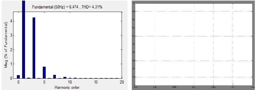
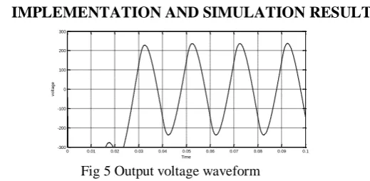
VII. IMPLEMENTATION AND SIMULATION RESULTS
Fig 5 Output voltage waveform
The low output voltage of PV panel into high AC voltage by using the flyback inverter. Because the flyback inverter has boosting capability without any additional circuit it can step up the voltage.
VIII. CONCLUSION
A low cost flyback inverter with sliding mode controller for AC module application has been proposed. Here the Sliding mode controller is used for tracking the maximum power from the PV panel .The flyback inverter is used to converter the direct current into alternating current. The total harmonic distortion of the flyback inverter is reduced by the LCL filter connected between inverter and load.
The main advantage of the flyback inverter is, it does not require any additional circuit to convert the low output voltage of PV panel into high voltage because it has capability to step up the voltage. MPPT or Maximum Power Point Tracking is algorithm that included in sliding mode controllers used for extracting maximum available power from PV module under certain conditions. The voltage at which PV module can produce maximum power is called maximum power point or peak power voltage. Maximum power varies with solar radiation, ambient temperature and solar temperature.
REFERENCES
[1] S. B. Kjaer,J.K.Pedesren, and F.Balabjerg, “A review of single-phase grid-connected inverters for photovoltaic modules,” IEEE Trans. Ind Appl., vol.41, no.5,pp. 1292-1306,Sep./Oct 2005.
[2] R.H. Wills, F.E. Hall, S. J. Strong and J. H. Wohlgemuth, “The AC photovoltaic module,” in Proc. 25th IEEE pPhotovolt. Spec. Conf., 1996, pp.. 1231–1234.
[3] T.Kerekes, R.Teodorescu, and U.Bourp, „Transformerless photovoltaic inverters connected to the grid,” in Proc. 22 nd Annu.IEEE Appl. Power Electron. Conf. (APEC), 2007, pp. 1733-1737.
[4] B .Burger and D.Kranzer, “Extreme high efficiency PV-power converters, in Proc.13th Eur.Conf. Power Electron. Appl. (EPE), 2009, pp. 1-13.
[5] U.Boeke and H.van der Broeck, “Transformer-less converter concept for a grid-connection of thin-film photovoltaic modules,” in Proc. IEEE Ind. Appl.Soc. Annu.Meet. (IAS), pp. 1-8.
[6] W.Yu, J.S. Lai, H. Qian and C.Hutchens, “High-efficiency MOSFET inverter W. Yu, J. S. Lai, H. Qian, and C. Hutchens, “High-efficiency MOSFET inverter with H6-type configuration for photovoltaic non-isolatedACmodule applications,” IEEE Trans. Power Electron., vol. 26, no. 4, pp. 1253– 1260, Apr. 2011.
[7] H. Patel and V. Agarwal, “A single-stage single-phase transformer-less doubly grounded grid-connected PV interface,” IEEE Trans. Energy Convers.vol. 24, no. 1, pp. 93–101, Mar. 2009.
[8] S. V. Araujo, P. Zacharias, and B. Sahan, “Novel grid-connected nonisolatedonverters for photovoltaic systems with grounded generator,” in Proc.IEEE Power Electron. Spec. Conf. (PESC), 2008, pp. 58–65.
[9] O. Abdel-Rahim, M. Orabi, and M. E. Ahmed, “Development of high gain high-efficiency grid-connected inverter for PVModule,” in Proc. 2nd
IEEE Int. Symp. Power Electron. Distrib. Generat. Syst. (PEDG), 2010, pp. 368–373. [10] C. Rodriguez and G. A. J. Amaratunga, “Long-lifetime power inverter forphotovoltaic AC modules,” IEEE Trans.
Ind. Electron., vol. 55, no. 7,pp. 2593–2601, Jul. 2008.LI AND ORUGANTI: A LOW COST FLYBACK CCM INVERTER FOR AC MODULE APPLICATION 1303
[11] N. P. Papanikolaou, E. C. Tatakis, A. Critsis, and D. Klimis, “Simplifiedhigh frequency converter in decentralized grid-connected PV systems:A novel low-cost solution,” in Proc. EPE’03, Toulouse, France, 2003, CD-ROM. [12] Y.-H. Ji, D.-Y. Jung, J.-H. Kim, C.-Y. Won, and D.-S. Oh, “Dual mode switching strategy of flyback inverter for
photovoltaic AC modules,” in Proc. Int. Power Electron. Conf. (IPEC), 2010, pp. 2924–2929. [13] A. C. Kyritsis, E. C. Tatakis, and N. P. Papanikolaou, “Optimum design of the current-source flyback inverter for decentralized grid-connectedphotovoltaic systems,” IEEE Trans. Energy Convers., vol. 23, no. 1, pp. 281–293, Mar. 2008. [14] C. E. Commission. (Feb. 2009). Emerging Renewables Program Guidebook (9th ed.) [Online].
0 0.01 0.02 0.03 0.04 0.05 0.06 0.07 0.08 0.09 0.1 -300
-200 -100 0 100 200 300
Time
v
o
lt
a
g
e