Microcontroller based Automatic Face Recognition
Attendance System
Siddharth Vohra
AITTM, Amity University, Noida (UP) Sector-125
Sagar Khattar
AITTM, Amity University, Noida (UP) Sector-125
Arvind Kumar
AITTM, Amity University, Noida (UP) Sector-125
ABSTRACT
The automatic face recognition attendance system was designed with the aim of marking attendance of the students present in a classroom based on facial recognition and give out a marked attendance sheet.
The system provides an efficient way of marking and storing the attendance without having to physically call out the name of each student. It helps save time and the attendance shall be directly stored without having to maintain a physical record.
General Terms
Face recognition, face detection, eigen-faces, eigen-vectors, servo motors, Arduino micro-controller, openCV, auto-focus, Laplace transform, webcam, Principle Component Analysis (PCA).
1.
INTRODUCTION
This project is based on C programming language and makes use of the Open CV library, developed by Intel and now maintained by Willow Garage and Itseez. Open CV (Open Source Computer Vision) is a library of programming functions for real time computer vision. Open CV provides pre-defined functions for face detection as well as for Eigen-faces which is the algorithm which has been used to recognize faces.
Face detection is the process of detecting a face in a frame whereas face recognition is the process of giving name to that face i.e. identifying the person. The project utilizes the Eigen faces algorithm for face recognition.
Servo motors are used to control a lens system which provides us with optical zoom and the focus is adjusted automatically using an auto-focus algorithm implemented in C program and making use of Open CV library. The C programming language is integrated with the Arduino microcontroller to provide serial communication, allowing us to control stepper motors from the C program itself.
1.1
How OpenCV stores images?
Open CV stores images as a C structure- IPL Image where IPL stands for Image Processing Library.
In addition to raw pixel data, it contains a number of descriptive fields, collectively called the Image Header. These include
• Width - image width in pixels.
• Height - image height in pixels.
• Depth - the number of bits per pixel per channel. For example, if depth=IPL_DEPTH_16U, data for each pixel channel are stored as sixteen-bit, unsigned values.
• nChannels - the number of data channels (from one to four). Each channel contains one type of pixel data. For example, Grayscale images contain only one channel - pixel brightness. RGB images have three channels - red, green, and blue intensities.
2.
Eigen faces for Face recognition
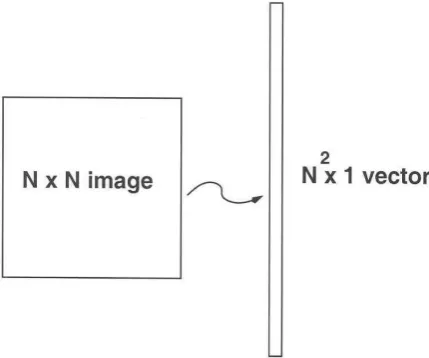
Eigen faces uses statistical approach to recognize unknown faces using a set of training face which we also refer to as the database of the students. Each face image is matrix of pixels which is viewed as a vector of length equal to the number of elements in the matrix. Consider for example a square (N*N) image of N2 pixels as shown in the Fig.1. It is equivalent to a vector of length N2 units, where each unit represents a pixel.
Figure 1: an image represented as a vector
Distance, also called Euclidean distance, is measured as the point-to-point distance. In two dimensions (2D), the Euclidean distance between points P1 and P2 is
where , and .
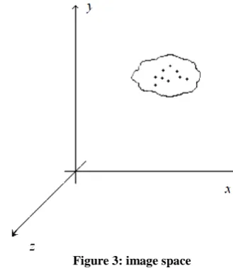
Hence we can infer that the whole of image space is not optimal for face description. Hence we aim to build a face space which better describes the face and the basis vectors of this face space are known as principal components. The dimensions of the image space are equal to the total number of pixels of the image. The dimensions of the face space cannot be determined but are far less than the dimensions of the image space.
In order to perform face recognition of an unknown face, we must have a database of face images of all the students in the classroom. At least 10 (120*120) face images of each student with variations in expressions and angle must be fed into the database. The Eigen faces algorithm works independent of the color of the skin; hence the face images are converted to grayscale and processed with histogram equalizer before being stored into the database.
The second step in the Eigen faces algorithm is to calculate the mean image of all the face images present in the database. This mean face image is then subtracted from each of the training face image.
where corresponds to the nth image in the database.
Next we calculate the eigen-vectors that correspond to the
highest eigen-values of the co-variance matrix of the set of training images.
The eigen-vectors can be thought of as a set of features which characterize the variation between face images. Eigen-vectors have ghostly face appearance; and hence are also referred to as eigen-faces as shown in Fig.3.
The technique of Principal Component Analysis (PCA) is used to generate the set of eigen-vectors (eigen-faces). The number of eigen-vectors is equal to the number of training face images in the database as shown in Fig.4.
The face images in the training set are then re-constructed by a weighted sum of a small set of characteristic images.
All the training face images are projected onto the face space. The test face images are also projected onto the face space and the distances between the test image and all the training face images are calculated. The Euclidean distance is used as the basis for calculating the distance between the face images. The training face image for which the Euclidean distance is the minimum is identified as the unknown face.
3.
Installing the lens system (optical zoom)
A webcam does not provide optical zooming capability; hence it does not prove to be very useful since the detected faces in the captured frames must have dimensions greater than 120*120 pixels (standard size). A webcam is able to do so only if the object (the person) is close enough; but in a classroom the students are situated at an appreciable distance from the whiteboard/webcam and hence the webcam is not very useful.In order to overcome this limitation a lens mechanism is installed in front of the webcam’s CCD sensor. The lens mechanism consists of a series of lenses divided into two sections- one for zooming and the other for focusing. Hence we can now zoom and focus accordingly by adjusting the zoom lens and focus lens respectively and the distance of the object from the webcam is no longer a limitation.
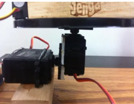
But with this advantage comes another problem of adjusting the zoom and focus lenses respectively separately. So in order to overcome this problem two separate servo motors are used and their armatures are connected to the lenses with the help of strings similar to a pulley system as shown in Fig.6. The servo motors are deliberately used for this purpose because they are easy to install and use, plus they are very compact
Figure 2: Eigen-vectors or Eigen-faces
and light. Also the servo motors can be controlled precisely and can provide feedback which helps us to know their present position.
4.
Rotation and Inclination
As the level of zoom increases the frame becomes smaller and smaller and is unable to capture all the faces in a single frame at a time. Hence in order to capture all the faces of the students present in a classroom, the frame must be rotated through an angle sufficient enough to cover the width of the classroom. Also since the webcam plus lens system was supposed to be mounted right above the whiteboard, a provision for inclination was required as well.
To provide the webcam plus lens system rotating capability it was mounted onto a third servo motor with its side further adhered to another fourth servo motor’s armature as shown in the Fig.6. The fourth servo motor was further adhered horizontally onto a heavy base to provide the whole system stability. With the help of the above steps the frame could be rotated and also the inclination could be adjusted accordingly to cover the entire classroom and capture all the faces of the students inside it irrespective of where they were seated in the classroom.
5.
Controlling the Servo Motors
In order to be able to control the servo motors efficiently a serial protocol was devised which allow us to control all the four servo motors directly from the C program itself by writing values to the serial port to which the Arduino was
connected. The drawback of using this serial port protocol was that it allow us to control only one servo motor at a time and not altogether.
The job of the Arduino was reduced to listening to the serial port and reading the serial data once it was available on the port. If the received serial data was equal to 111 then the next subsequent serial data was used to position the zoom servo motor, else if it was 222 the next subsequent serial data was used to position the focus servo motor, else if it was 333 the next subsequent serial data was used to position the rotation servo motor, else if it was 444 the next subsequent serial data was used to position the inclination servo motor. These values were chosen arbitrarily.
After writing the value to position the respective servo motor, if the next received serial data was equal to 1, then the subsequent received serial data was used to again position the same servo and so on in a loop. If the received serial data after positioning the servo was equal to 0, then the loop was exited and the subsequent serial data was used to decide which servo motor to control.
6.
Autofocus mechanism
The focus of the image needs to be adjusted every time the zoom level is changed. One way to go about adjusting the focus is to determine the focus values for each zoom level before-hand and then use them during run-time. This method is static in nature and may produce enormous errors for slightest change in the physical layout of the classroom. The other way is to let Open CV determine the focus on its own by analyzing the captured frames. The method is dynamic in nature but is a little more time consuming than the former.
In order to set the focus automatically we need to analyze the captured frames at all points within the focus range and determine the point which corresponds to the sharpest captured frame.
The autofocus mechanism is based on the Laplace Transform. Open CV provides inbuilt function Laplace( ) to calculate the Laplace Transform. The function calculates the Laplacian of the source image by summing up the second order x and y derivatives calculated using the Sobel operator. The Laplacian operator is given by
Figure 5: Principle Component Analysis (PCA)
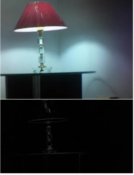
The Laplace( ) function takes in an input greyscale image and processes it with Laplace Transform to give an output image which reflects all the sharp points in the input image. The more focused the image, the sharper it will be and hence higher will be the intensity of pixels in greyscale.
In 8- bit greyscale the intensity of pixels is expressed from 00000000 corresponding to zero intensity (black) to 11111111 corresponding to highest intensity (white). The better focused the image; higher will be the intensity of pixels i.e. it will be more towards white and hence higher will be the pixel values as shown in Fig &.
The entire focus range was divided into 20 steps and a frame was captured for each step. The captured frames were converted to greyscale and then processed with Laplace Transform. The processed frames were then compared with each other and the one with the highest pixel value was chosen as the best focus step. The best focus step is then passed to the Arduino micro-controller which adjusts the focus servo.
6.1
A. Sample program for auto-focus
#include <stdio.h>
#include <opencv2/imgproc/imgproc.hpp> #include <opencv2/imgproc/imgproc_c.h> #include <opencv2/highgui/highgui.hpp> int main() {
FILE* fp=fopen("/dev/ttyACM0","w"); CvCapture* pCapture=cvCaptureFromCAM(1); cvSetCaptureProperty(pCapture,CV_CAP_PROP _FRAME_WIDTH,1280);
cvSetCaptureProperty(pCapture,CV_CAP_PROP _FRAME_HEIGHT,720);
IplImage**
capture_arr=(IplImage**)cvAlloc(20*sizeof (IplImage*));
IplImage**
grey_arr=(IplImage**)cvAlloc(20*sizeof(Ip lImage*));
IplImage**
laplace_arr=(IplImage**)cvAlloc(20*sizeof (IplImage*));
IplImage**
abs_laplace_arr=(IplImage**)cvAlloc(20*si zeof(IplImage*));
int max_pos=0;
cvNamedWindow("win",CV_WINDOW_AUTOSIZE); for(int step=0;step<20;step++) {
char path[]="/home/siddharth/minor-project/";
char temp[100]; int a=step/10; int b=step%10; temp[0]=48+a; temp[1]=48+b; temp[2]='\0';
strcat(temp,".png"); strcat(path,temp); int f_step=step+30;
fprintf(fp,"%d\n",f_step);
capture_arr[step]=cvQueryFrame(pCapture); grey_arr[step]=cvCreateImage(cvSize(1280, 720),IPL_DEPTH_8U,1);
cvCvtColor(capture_arr[step],grey_arr[ste p],CV_BGR2GRAY);
laplace_arr[step]=cvCreateImage(cvSize(12 80,720),IPL_DEPTH_32F,1);
cvLaplace(grey_arr[step],laplace_arr[step ],1);
abs_laplace_arr[step]=cvCreateImage(cvSiz e(1280,720),IPL_DEPTH_8U,1);
cvConvertScaleAbs(laplace_arr[step],abs_l aplace_arr[step], 1, 0);
cvShowImage("win",abs_laplace_arr[step]); cvSaveImage(path,abs_laplace_arr[step]); cvWaitKey(1000);
}
short max_lap_k[20]; for(int k=0;k<20;k++)
Figure 8: the focus lens is connected to the servo motor which displaces it in small steps
{
short maxLap = -32767;
short* imgData =
(short*)abs_laplace_arr[k]->imageData; for(int i =0;i<(abs_laplace_arr[k]->imageSize/2);i++)
{
if(imgData[i] > maxLap) maxLap = imgData[i];
}
max_lap_k[k]=maxLap; }
for(int l=0;l<19;l++) {
if(max_lap_k[max_pos]<max_lap_k[l+1]) {
max_pos=l+1; }
}
int f_max=max_pos+30-6; fprintf(fp,"%d\n",f_max); cvReleaseCapture(&pCapture); cvReleaseImage(capture_arr); cvReleaseImage(grey_arr); cvReleaseImage(laplace_arr); cvReleaseImage(abs_laplace_arr); fclose(fp);
return 0; }
7.
Runtime algorithm
The system is initialized as follows:1. The rotation and inclination servos are adjusted so that the system points to one end of the first row of the classroom.
2. The zoom level is adjusted sufficiently enough to detect faces greater than size (120*120).
Then the face recognition process is started and the system is rotated through an angle sufficient enough to make the system point to the other end of the row while the face recognition process continues to run along with it. During the rotation the system captures frames continuously and detects faces in it, which are there after extracted, resized, processed with histogram equalizer and then recognized. This process continues while the system is rotating to the other end and then back to its initial position.
The face recognition process is then paused and the inclination is incremented so that the system points to one end on the same side of the next row. The zoom level is then incremented sufficiently to capture faces of the students greater than 120*120 pixels. The system is again rotated and the face recognition process is resumed simultaneously until it reaches the other end and back. The above steps are repeated until all the rows of the classroom are covered.
After the whole of the classroom is covered, the system is reset to its initial position and started all over again. It is run for several rounds throughout the duration of the lecture.
At the end of the lecture if the total number of times a student’s face is recognized is above a certain threshold value, then he/she is marked present for the lecture, else he/she is marked absent. This step is taken to overcome any errors which may have been produced during the face recognition process.
8.
Conclusion
The system provides an efficient way of marking and storing the attendance without having to physically call out the name of each student. It helps save time and the attendance can be directly stored without having to maintain a physical record. Its algorithm for face recognition can be updated easily without an expense with advancement in technology. The system will also help save tons of paper which is wasted every academic year maintaining attendance of the students in schools and colleges throughout the globe.
9.
REFERENCES
[1] M. Turk and A. Pentland (1991). "Face recognition using eigenfaces". Proc. IEEE Conference on Computer Vision and Pattern Recognition.
[2] “Seeing With OpenCV” - A Five-Part Series by Robin Hewitt, published in the SERVO magazine 2007 issue.
[3] M. Turk, A Random Walk through Eigenspace, IEICE Transactions on Information and Systems, Vol. E84-D, No. 12, December 2001, pp. 1586-1595K. Elissa, “Title of paper if known,” unpublished.
[4] Learning OpenCV: Computer Vision with the OpenCV Library [Paperback] Gary Bradski(Author), Adrian Kaehler.